Download to read offline

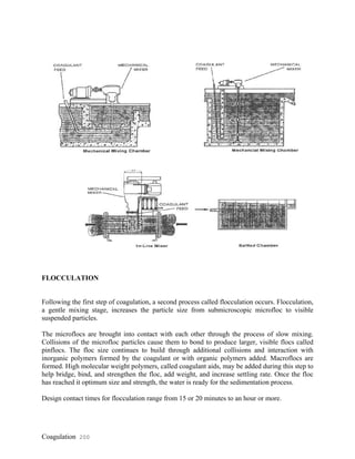
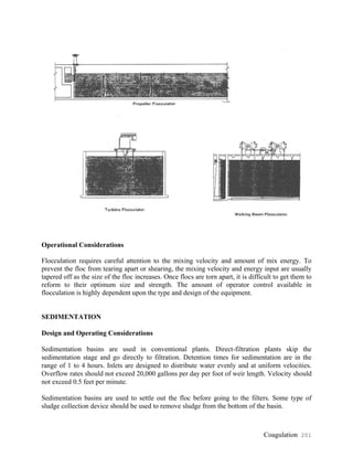
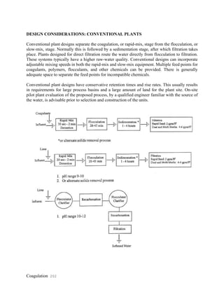
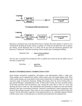
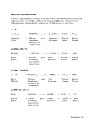

Coagulation and flocculation processes are used to separate suspended solids from water by overcoming the forces that stabilize the particles and allow them to collide and grow into larger flocs. Coagulation involves adding chemicals to neutralize particle charges so they can stick together. Flocculation then gently mixes the water to encourage the microflocs formed in coagulation to collide and bond into larger macroflocs that are easy to remove. Conventional treatment plants separate coagulation, flocculation, and sedimentation into distinct stages, while other designs combine some or all of the processes in single units. Careful consideration of water characteristics and treatment goals is needed to select the appropriate coagulant and unit processes.