Downloaded 1,197 times


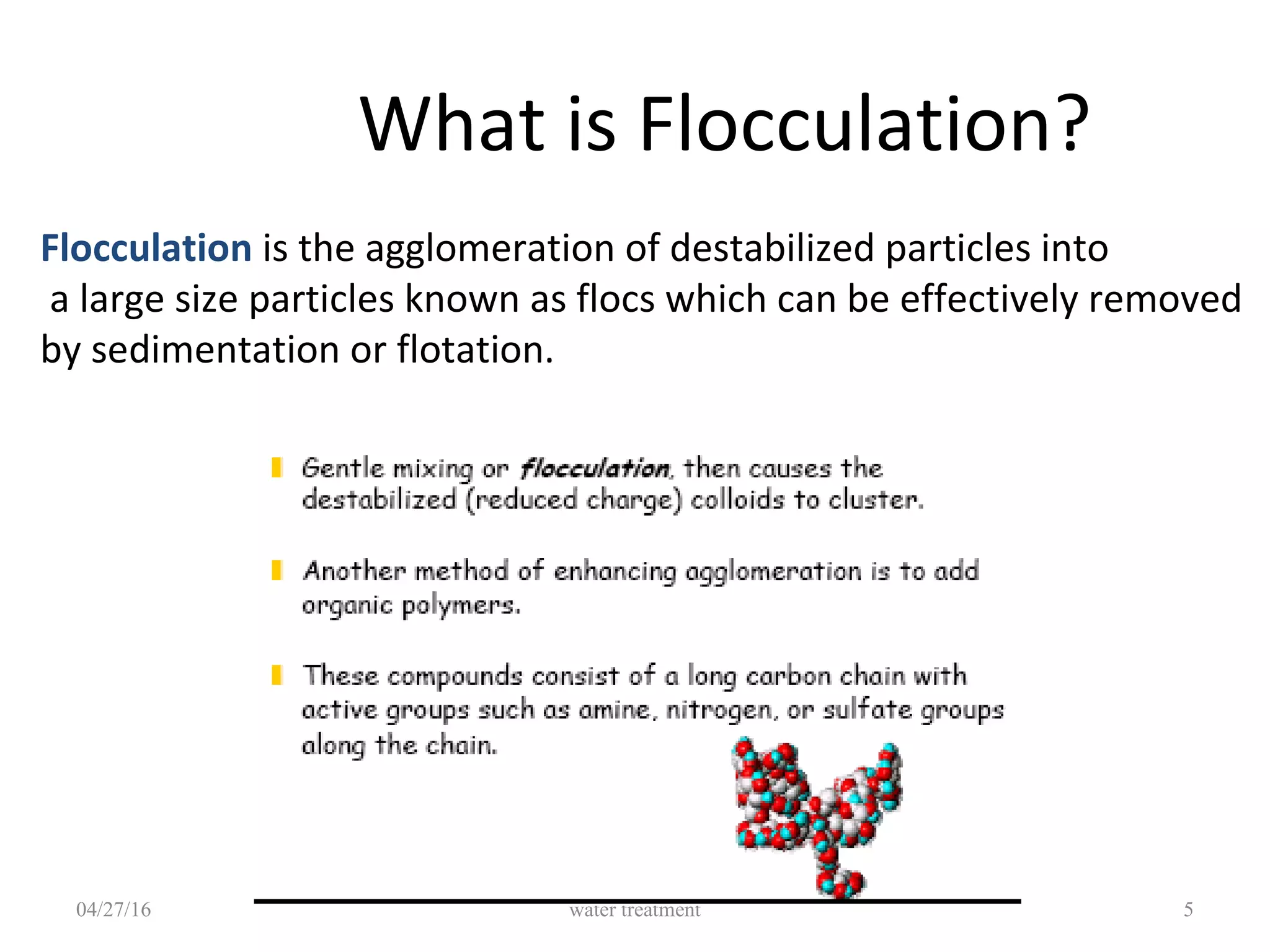
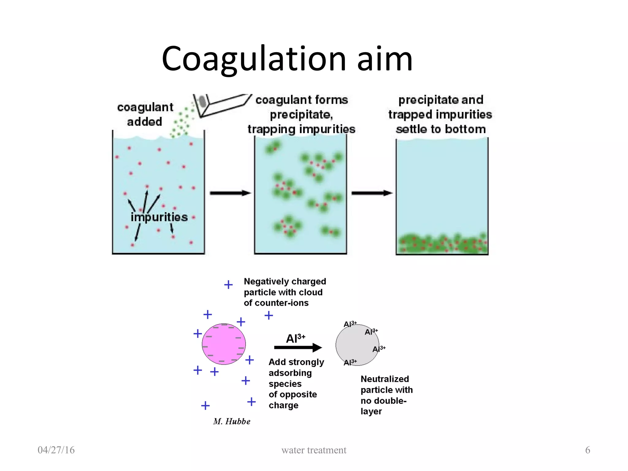
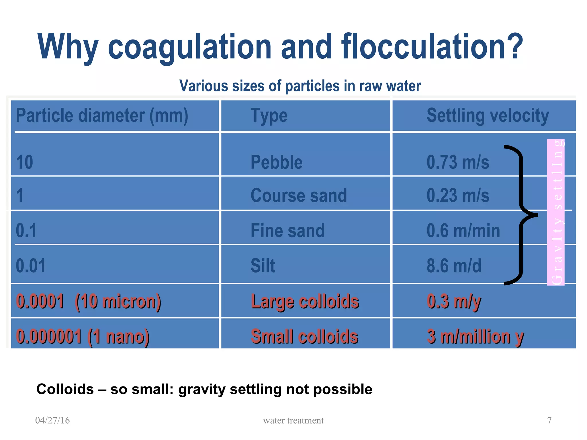
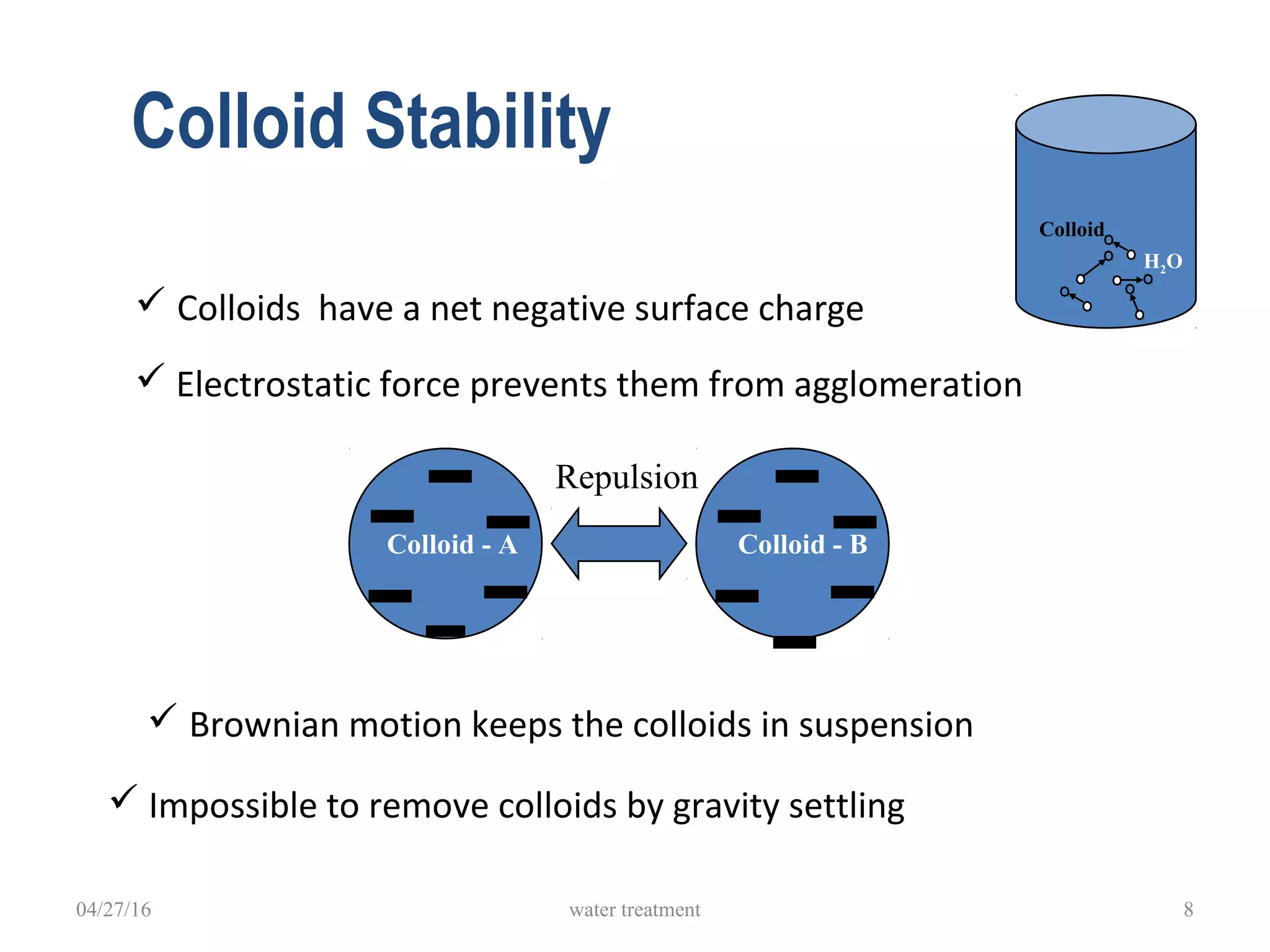


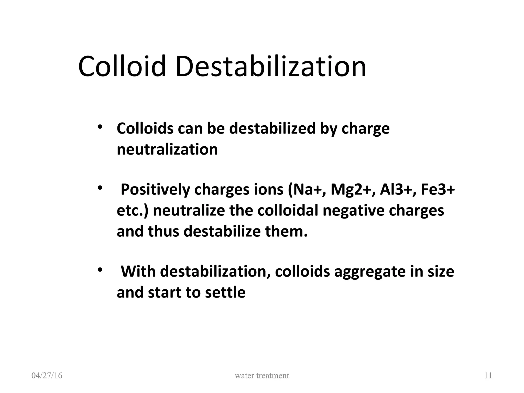


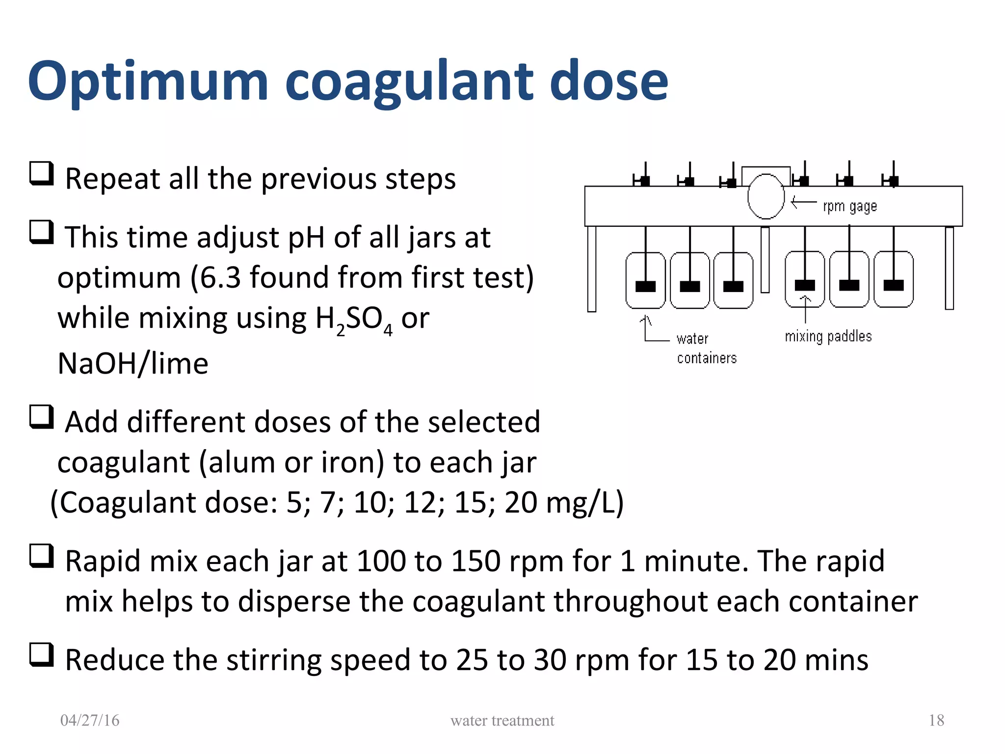


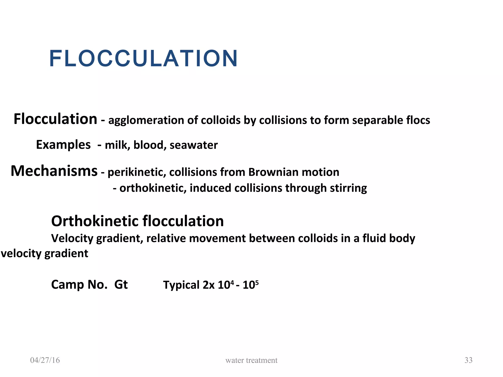
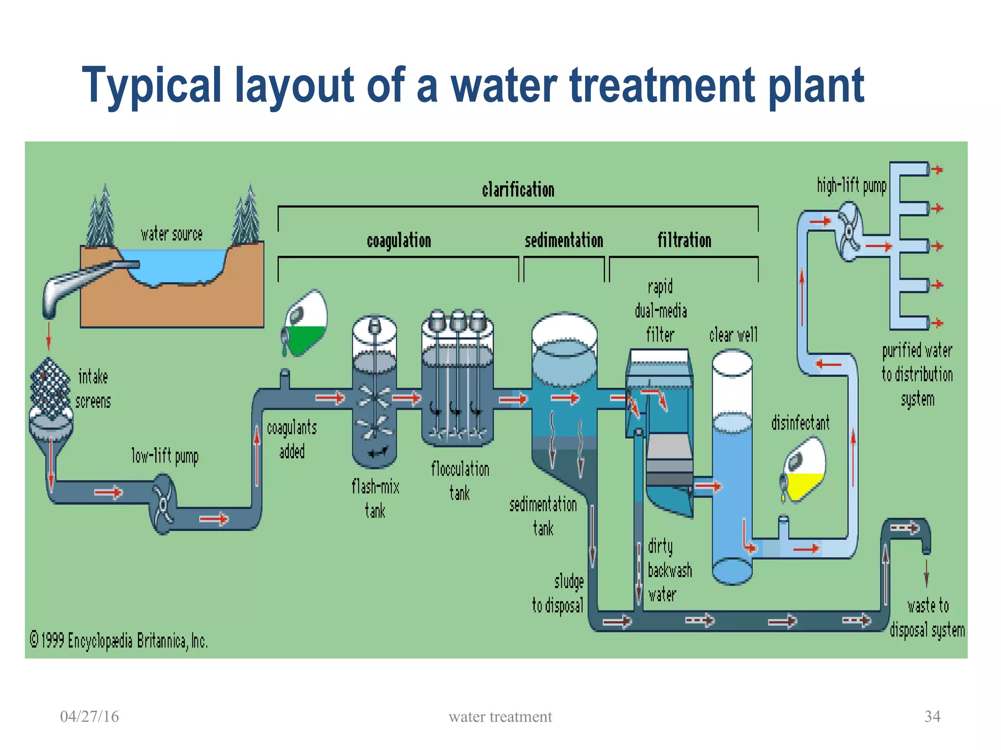


The document discusses coagulation and flocculation processes in water treatment. It describes how coagulation uses chemicals like aluminum sulfate and ferric chloride to neutralize negatively charged colloids in water. Flocculation is the process where these destabilized particles agglomerate into larger floc particles that can be removed through sedimentation or flotation. Jar tests are used to determine the optimum pH and coagulant dose. Various types of flocculators including hydraulic, mechanical, and differential settling designs are presented to gently mix water and promote floc formation and settling.


![Lecture 9 -_centralized_water_treatment_(treatment_and_disinfection)[1]](https://cdn.slidesharecdn.com/ss_thumbnails/lecture9-centralizedwatertreatmenttreatmentanddisinfection1-150122150953-conversion-gate02-thumbnail.jpg?width=640&height=640&fit=bounds)


