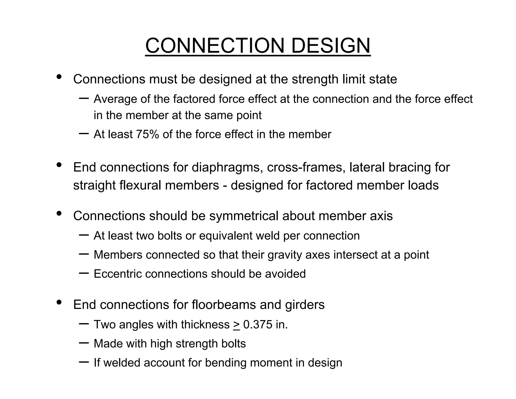
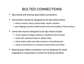
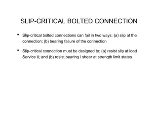
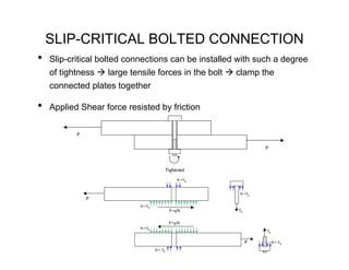
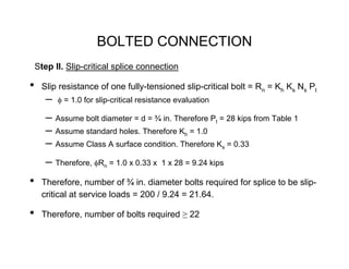
SlideShare a Scribd company logo
1 of 33
Download to read offline
CONNECTION DESIGN
•   Connections must be designed at the strength limit state
     – Average of the factored force effect at the connection and the force effect
       in the member at the same point
     – At least 75% of the force effect in the member
•   End connections for diaphragms, cross-frames, lateral bracing for
    straight flexural members - designed for factored member loads

•   Connections should be symmetrical about member axis
     – At least two bolts or equivalent weld per connection
     – Members connected so that their gravity axes intersect at a point
     – Eccentric connections should be avoided
•   End connections for floorbeams and girders
     – Two angles with thickness > 0.375 in.
     – Made with high strength bolts
     – If welded account for bending moment in design
BOLTED CONNECTIONS
•   Slip-critical and bearing type bolted connections.

•   Connections should be designed to be slip-critical where:
     – stress reversal, heavy impact loads, severe vibration
     – joint slippage would be detrimental to the serviceability of the structure
•   Joints that must be designed to be slip-critical include
     – Joints subject to fatigue loading or significant load reversal.
     – Joints with oversized holes or slotted holes
     – Joints where welds and bolts sharing in transmitting load
     – Joints in axial tension or combined axial tension and shear
•   Bearing-type bolted connections can be designed for joints
    subjected to compression or joints for bracing members
SLIP-CRITICAL BOLTED CONNECTION

•   Slip-critical bolted connections can fail in two ways: (a) slip at the
    connection; (b) bearing failure of the connection

•   Slip-critical connection must be designed to: (a) resist slip at load
    Service II; and (b) resist bearing / shear at strength limit states
SLIP-CRITICAL BOLTED CONNECTION
•   Slip-critical bolted connections can be installed with such a degree
    of tightness   large tensile forces in the bolt    clamp the
    connected plates together

•   Applied Shear force resisted by friction

           P

                                                                P


                                         Tightened

                                               N =Tb


                                                       N =Tb
               P
                            N =Tb
                                             F=μN      Tb


                                             F=μN
                            N =Tb
                                                                Tb


                                                            P        N = Tb

                                    N = Tb
SLIP-CRITICAL BOLTED CONNECTION
•   Slip-critical connections can resist the shear force using friction.
     – If the applied shear force is less than the friction that develops between
       the two surfaces, then no slip will occur between them

•   Nominal slip resistance of a bolt in a slip-critical connection
     – Rn = Kh Ks Ns Pt
     – Where, Pt = minimum required bolt tension specified in Table 1
       Kh = hole factor specified in Table 1
       Ks = surface condition factor specified in Table 3
SLIP-CRITICAL BOLTED CONNECTION
                                                        Values of Kh
                                        For standard holes                     1.0
                  Values of Pt          For oversize and short-slotted holes 0.85
    Bolt diameter    Required Tension
         (in.)            (kips)        For long slotted holes with the slot   0.70
                     A325        A490   Perpendicular to the force direction
          5/8          19          24
                                        For long-slotted holes with the slot   0.60
          3/4          28          35
          7/8          39          49
                                        Parallel to the force direction
           1           51          64
                                                        Values of Ks
        1-1/8          56          80
        1-1/4          71         102    For Class A surface conditions 0.33
        1-3/8          85         121
        1-1/2         103         148    For Class B surface conditions 0.50

                                         For Class C surface conditions 0.33
•   Faying surfaces
      – Unpainted clean mill scale, and blast-cleaned surfaces with Class A coating
      – Unpainted blast-cleaned surfaces with Class B coating
      – Hot-dip galvanized surfaces roughened by wire brushing – Class C
SLIP-CRITICAL CONNECTION

•   Connection subjected to tensile force (Tu), which reduces clamping
     – Nominal slip resistance should be reduced by (1- Tu/Pt)
•   Slip is not a catastrophic failure limit-state because slip-critical
    bolted connections behave as bearing type connections after slip.

•   Slip-critical bolted connections are further designed as bearing-type
    bolted connection for the applicable factored strength limit state.
BEARING CONNECTION
•   In a bearing-type connection, bolts are subjected to shear and the
    connecting / connected plates are subjected to bearing stresses :

         T
                                                             T


                              Bearing stresses in plate
         T
                                             Bolt in shear

                                                             T
                              Bearing stresses in plate
BEARING CONNECTION

•   Bearing type connection can fail in several failure modes
    a) Shear failure of the bolts
    b) Excessive bearing deformation at the bolt holes in the connected parts
    c) Edge tearing or fracture of the connected plate
    d) Tearing or fracture of the connected plate between two bolt holes
    e) Failure of member being connected due to fracture or block shear or ...
BEARING CONNECTION
•   Nominal shear resistance of a bolt
     – Threads excluded:               Rn = 0.48 Ab Fub Ns
     – Threads included:               Rn = 0.38 Ab Fub Ns
     Where, Ab = area of the bolt corresponding to the nominal diameter
       Fub = 120 ksi for A325 bolts with diameters 0.5 through 1.0 in.
       Fub = 105 ksi for A325 bolts with diameters 1.125 through 1.5 in.
       Fub = 150 ksi for A490 bolts.
       Ns = number of shear planes

•   Resistance factor for bolts in shear = φs = 0.80
•   Equations above - valid for joints with length < less than 50.0 in.
     – If the length is greater than 50 in., then the values from the equations
       have to be multiplied by 0.8
BEARING CONNECTION
•   Effective bearing area of a bolt = the bolt diameter multiplied by the
    thickness of the connected material on which it bears
•   Bearing resistance for standard, oversize, or short-slotted holes in any
    direction, and long-slotted holes parallel to the bearing force:
     –   For bolts spaced with clear distance between holes greater than or equal to 3.0 d
         and for bolts with a clear end distance greater than or equal to 2.0 d
                                         Rn = 2.4 d t Fu
     –   For bolts spaced with clear distance between holes less than 3.0 d
         and for bolts with clear end distances less than 2.0 d

                                       Rn = 1.2 Lc t Fu
     Where, d = nominal bolt diameter
     Lc= clear distance between holes or between the hole and the end of the member in
         the direction of applied bearing force
     Fu = tensile strength of the connected material


•   The resistance factor φbb for material in bearing due to bolts = 0.80
BEARING CONNECTION
•   SPACING REQUIREMENTS
    – Minimum spacing between centers of bolts in standard holes shall not
      be less than three times the diameter of the bolt
    – For sealing against penetration of moisture in joints, the spacing on a
      single line adjacent to the free edge shall satisfy s ≤ (4.0 + 4.0 t) ≤ 7.0
    – Minimum edge distances
        Bolt diameter   Sheared      Rolled or
             (in.)       edge       Gas Cut edge
              5/8        1-1/8          7/8
              3/4        1-1/4           1
              7/8        1-1/2         1-1/8
               1         1-3/4         1-1/4
            1-1/8          2           1-1/2
            1-1/4        2-1/4         1-5/8
            1-3/8        2-3/8         1-3/4
BOLTED CONNECTION
•   Example 1 Design a slip-critical splice for a tension member. For
    the Service II load combination, the member is subjected to a
    tension load of 200 kips. For the strength limit state, the member is
    subjected to a maximum tension load of 300 kips.
     – The tension member is a W8 x 28 section made from M270-Gr. 50
       steel. Use A325 bolts to design the slip-critical splice.

•   Step I. Service and factored loads
     – Service Load = 200 kips.
     – Factored design load = 300 kips
     – Tension member is W8 x 28 section made from M270 Gr.50. The
       tension splice must be slip critical (i.e., it must not slip) at service loads.
BOLTED CONNECTION
    Step II. Slip-critical splice connection

•    Slip resistance of one fully-tensioned slip-critical bolt = Rn = Kh Ks Ns Pt
       –   φ = 1.0 for slip-critical resistance evaluation

       – Assume bolt diameter = d = ¾ in. Therefore Pt = 28 kips from Table 1
       – Assume standard holes. Therefore Kh = 1.0
       – Assume Class A surface condition. Therefore Ks = 0.33
       – Therefore, φRn = 1.0 x 0.33 x     1 x 28 = 9.24 kips

•    Therefore, number of ¾ in. diameter bolts required for splice to be slip-
     critical at service loads = 200 / 9.24 = 21.64.

•    Therefore, number of bolts required ≥ 22
BOLTED CONNECTION


Step III: Layout of flange-plate splice connection
•   To be symmetric about centerline, need the number of bolts = multiple of 8.
•   Therefore, choose 24 fully tensioned 3/4 in. A325 bolts with layout above.
     –   Slip-critical strength of the connection = 24 x 9.24 kips = 221.7 kips
•   Minimum edge distance (Le) = 1 in. from Table 4.
     –   Design edge distance Le = 1.25 in.
•   Minimum spacing = s = 3 x bolt diameter = 3 x ¾ = 2.25 in.
     –   Design spacing = 2.5 in.
BOLTED CONNECTION
Step IV: Connection strength at factored loads
•   The connection should be designed as a normal shear/bearing
    connection beyond this point for the factored load of 300 kips

•   Shear strength of high strength bolt = φ Rn = 0.80 x 0.38 x Ab x Fub Ns
     – Equation given earlier for threads included in shear plane.
     – Ab = 3.14 x 0.752 / 4 = 0.442 in2
     – Fub = 120 ksi for A325 bolts with d < 1-1/8 in.
     – Ns= 1
     – Therefore, φRn = 16.1 kips
•   The shear strength of 24 bolts = 16.1 kips/bolt x 24 = 386.9 kips
BOLTED CONNECTION
•   Bearing strength of 3/4 in. bolts at edge holes (Le = 1.25 in.)
     –   φbb Rn = 0.80 x 1.2 Lc t Fu
          Because the clear edge distance = 1.25 – (3/4 + 1/16)/2 = 0.84375 in. < 2 d
     –   φbb Rn = 0.80 x 1.2 x 0.84375 x 65 kips x t = 52.65 kips / in. thickness

•   Bearing strength of of 3/4 in. bolts at non-edge holes (s = 2.5)
     –   φbb Rn = 0.80 x 2.4 d t Fu
          Because the clear distance between holes = 2.5 – (3/4 + 1/16) = 1.6875 in. > 2d
     –   φbb Rn = 0.80 x 2.4 x 0.75 x 65 kips x t = 93.6 kips / in. thickness

•   Bearing strength of bolt holes in flanges of wide flange section W8 x 28
    (t = 0.465 in.)
     – 8 x 52.65 x 0.465 +16 x 93.6 x 0.465 = 892 kips
CONNECTION STRENGTH

Connection Strength

Slip-critical strength = 221.7 kips

Shear strength of bolts = 386.9 kips

Bearing strength (plate) = 892 kips


•   Connection strength (φRn) > applied factored loads (γQ).
      – Therefore ok
WELDED CONNECTIONS
•   Introduction
     – The shielded metal arc welding (SMAW) process for field welding.
     – Submerged metal arc welding (SAW) used for shop welding –
       automatic or semi-automatic process
     – Quality control of welded connections is particularly difficult because of
       defects below the surface, or even minor flaws at the surface, will
       escape visual detection.
     – Welders must be properly certified, and for critical work, special
       inspection techniques such as radiography or ultrasonic testing must
       be used.
WELDED CONNECTIONS
•   Two most common types of welds are the fillet and the groove weld.
     – lap joint – fillet welds placed in the corner formed by two plates
     – Tee joint – fillet welds placed at the intersection of two plates.
•   Groove welds – deposited in a gap or groove between two parts to be
    connected e.g., butt, tee, and corner joints with beveled (prepared) edges
     –   Partial penetration groove welds can be made from one or both sides with or
         without edge preparation.


                                                                      Fillet weld


                                Fillet weld
WELDED CONNECTIONS
    •   Design of fillet welded connections
         – Fillet welds are most common and used widely
         – Weld sizes are specified in 1/16 in. increments
         – Fillet welds are usually fail in shear, where the shear failure occurs
           along a plane through the throat of the weld
•


                                                              L
                                    Throat = a x cos45o
                       a                   = 0.707 a


                                a
                                                                            Failure Plane


         – Shear stress in fillet weld of length L subjected to load P
                      P
           fv =
                  0.707 a L w
FILLET WELDED CONNECTIONS
•   The shear strength of the fillet weld = φe2 0.60 Fexx
     – Where, φe2 = 0.80
     – Fexx is the tensile strength of the weld electrode used in the welding
         process. It can be 60, 70, 80, 90, 100, 110, or 120 ksi. The corresponding
         electrodes are specified using the nomenclature E60XX, E70XX, E80XX,
         and so on.

•   Therefore, the shear strength of the fillet weld connection
     –   φRn = φe2 x 0.60 Fexx x 0.707 a Lw

•   Electrode strength should match the base metal strength
     – If yield stress (σy) of the base metal is ≤ 60 - 65 ksi, use E70XX electrode
     – If yield stress (σy) of the base metal is ≥ 60 - 65 ksi, use E80XX electrode
•   E70XX is the most popular electrode used for SMAW fillet welds
     – For E70XX, φRn = 0.80 x 0.60 x 70 x 0.707 a     Lw = 0.2375 a Lw kips
FILLET WELDED CONNECTIONS
•   The shear strength of the base metal must be considered:
    –   φ Rn = φv x 0.58 Ag Fy
    where, φv = 1.0
        Fy is the yield strength of the base metal and Ag is the gross area in shear
               T


                                                                      Plan
                   Elevation


          Strength of weld in shear                          Strength of base metal
        = 0.80 x 0.60 x Fexx x 0.707 x a x Lw                = 1.0 x 0.58 x Fy x t x Lw


                               Smaller governs the strength of the weld
FILLET WELDED CONNECTIONS
Limitations on weld dimensions
•   Minimum size (amin)
    – Weld size need not exceed the thickness of the thinner part joined.
    – amin depends on the thickness of the thicker part joined
    – If the thickness of the thicker part joined (T) is less than or equal to ¾ in.
          amin = ¼ in.
    – If T is greater than ¾ in.    amin = 5/16 in.

•   Maximum size (amax)
    – Maximum size of fillet weld along edges of connected parts
    – for material with thickness < 0.25 in., amax- = thickness of the material
    – for plates with thickness ≥ 0.25 in., amax = thickness of material - 1/16 in.
•   Minimum length (Lw)
    – Minimum effective length of fillet weld = 4 x size of fillet weld
    – Effective length of fillet weld > 1.5 in.
FILLET WELDED CONNECTIONS

•   Weld terminations and end returns
    – End returns must not be provided around transverse stiffeners
    – Fillet welds that resist tensile forces not parallel to the weld axis or
       proportioned to withstand repeated stress shall not terminate at corners
       of parts or members
    – Where end returns can be made in the same plane, they shall be
       returned continuously, full size around the corner, for a length equal to
       twice the weld size (2a)
FILLET WELD DESIGN
Example 1 Design the fillet welded connection system for a double
    angle tension member 2L 5 x 3½ x 1/2 made from A36 steel to carry
    a factored ultimate load of 250 kips.

Step I. Design the welded connection
     Considering only the thickness of the angles; amin = 1/4 in.
     Considering only the thickness of the angles; amax = 1/2 - 1/16 in. = 7/16 in.
     Design, a = 3/8 in. = 0.375 in.
§      Shear strength of weld metal = φ Rn = 0.80 x 0.60 x FEXX x 0.707 x a x Lw
                                 = 8.9 x Lw kips
Strength of the base metal in shear = φ Rn = 1.0 x 0.58 x Fy x t x Lw
                                 = 10.44 Lw kips
§     Shear strength of weld metal governs, φ Rn = 8.9 Lw kips
FILLET WELD DESIGN
•   Design strength φ Rn > 250 kips
     – Therefore, 8.9 Lw > 250 kips
     – Therefore, Lw > 28.1 in.
•   Design length of 3/8 in. E70XX fillet weld = 30.0 in.

•   Shear strength of fillet weld = 267 kips
•   Connection layout
     – Connection must be designed to minimize eccentricity of loading.
       Therefore, the center or gravity of the welded connection must coincide
       with the center of gravity of the member.
                                          L1
                                              f L1

                        Tu                            3.4 in.

                                       f L2

                                                 L2
FILLET WELD DESIGN
•   Connection layout
    – Connection must be designed to minimize eccentricity of loading.
    – The c.g. of the welded connection must coincide with c.g. of the member
                                     L1
                                         f L1


             Tu                                  3.4 in.

                                  f L2

                                            L2

    – Total length of weld required = 30 in.
    – Two angles assume each angle will have weld length of 15 in.
FILLET WELD DESIGN

•   The tension force Tu acts along the c.g. of the member, which is
    1.65 in. from the top and 3.35 in. from the bottom (AISC manual).
     – Let, f be the strength of the fillet weld per unit length.
        Therefore, fL1 + fL2 = Tu
     And fL2 x 3.35 - fL1 x 1.65 = 0 - taking moments about the member c.g.
     – Therefore, L1 = 2.0 L2
        But, L1 + L2 = 15.0 in.
     – Therefore, L1 = 10 in. and L2 = 5 in.

Design: L1 = 10.0 in. and L2 = 5.0 in.
FILLET WELD DESIGN
•   Consider another layout
                                          L1
                                          f L1


              Tu                                            5f       3.4 in
                                         f L2

                                                 L2
    fL1 + fL2 + 5f = Tu

    fL2 x 3.5 + 5f x 0.85 - fL1 x 1.65 = 0 - Moment about member c.g.

    Additionally,     L1 + L2 + 5 = 15.0 in.

    Therefore,        L1 = 7.6 in.     and            L2 = 2.4 in.

    Design: L1 = 8.0 in.       and     L2 = 3.0 in.
Groove Welded Connections
•   Connects structural members that are aligned in the same plane
•   Basic Types:
     –   Complete joint penetration groove weld: transmits full load of the member they join
         and have the same strength as the base metal.
     –   Partial penetration groove weld: Welds do not extend completely through the
         thickness of the pieces being joined.
Groove Welds
Complete penetration groove welded connections
•   Tension and compression loaded
     – Factored resistance   = factored resistance of base metal
•   Shear loaded on effective area        lesser of
     – Factored resistance of weld = 0.6 x φe1 x Fexx = 0.6 x 0.85 x Fexx
     – 60% of factored resistance of base metal in tension
Partial penetration groove-welded connections
•   Tension or compression parallel to the weld axis and compression normal
    to effective area factored resistance of the base metal
•   Tension normal to the effective area        lesser of
     – Factored resistance of the weld = 0.6 φe2 Fexx = 0.60 x 0.80 x Fexx
     – Factored resistance of the base metal
•   Shear loaded       lesser of
     – Factored resistance of the weld = 0.6 φe2 Fexx = 0.60 x 0.80 x Fexx
     – Factored resistance of base metal = 0.58 Fy
Groove Welds

More Related Content

What's hot

Design of two way slab
Design of two way slabDesign of two way slab
Design of two way slabsarani_reza
 
Design calculations of raft foundation
Design calculations of raft foundationDesign calculations of raft foundation
Design calculations of raft foundationShahzad Ali
 
Column base plates_prof_thomas_murray
Column base plates_prof_thomas_murrayColumn base plates_prof_thomas_murray
Column base plates_prof_thomas_murrayAlberto Rosado
 
Bending stresses in beams
Bending stresses in beams Bending stresses in beams
Bending stresses in beams JISHNU V
 
Design of R.C.C Beam
Design of R.C.C BeamDesign of R.C.C Beam
Design of R.C.C BeamAr. Aakansha
 
Isolated footing design
Isolated footing designIsolated footing design
Isolated footing designsrinu_anduri
 
L- beams or flanged beams
L- beams or flanged beamsL- beams or flanged beams
L- beams or flanged beamshoneysid
 
Shear Force And Bending Moment Diagram For Frames
Shear Force And Bending Moment Diagram For FramesShear Force And Bending Moment Diagram For Frames
Shear Force And Bending Moment Diagram For FramesAmr Hamed
 
Design and Detailing of RC Deep beams as per IS 456-2000
Design and Detailing of RC Deep beams as per IS 456-2000Design and Detailing of RC Deep beams as per IS 456-2000
Design and Detailing of RC Deep beams as per IS 456-2000VVIETCIVIL
 
Design of columns uniaxial load as per IS 456-2000
Design of columns  uniaxial load as per IS 456-2000Design of columns  uniaxial load as per IS 456-2000
Design of columns uniaxial load as per IS 456-2000PraveenKumar Shanmugam
 
Connections
ConnectionsConnections
Connectionssky hawk
 

What's hot (20)

Bolted connections
Bolted connectionsBolted connections
Bolted connections
 
Design of two way slab
Design of two way slabDesign of two way slab
Design of two way slab
 
Design calculations of raft foundation
Design calculations of raft foundationDesign calculations of raft foundation
Design calculations of raft foundation
 
Column base plates_prof_thomas_murray
Column base plates_prof_thomas_murrayColumn base plates_prof_thomas_murray
Column base plates_prof_thomas_murray
 
Design of footing as per IS 456-2000
Design of footing as per IS 456-2000Design of footing as per IS 456-2000
Design of footing as per IS 456-2000
 
Compression member
Compression memberCompression member
Compression member
 
Bending stresses in beams
Bending stresses in beams Bending stresses in beams
Bending stresses in beams
 
Design of R.C.C Beam
Design of R.C.C BeamDesign of R.C.C Beam
Design of R.C.C Beam
 
Plate notes
Plate notes Plate notes
Plate notes
 
Bearing 2
Bearing 2Bearing 2
Bearing 2
 
ONE WAY SLAB DESIGN
ONE WAY SLAB DESIGNONE WAY SLAB DESIGN
ONE WAY SLAB DESIGN
 
Footing design
Footing designFooting design
Footing design
 
Isolated footing design
Isolated footing designIsolated footing design
Isolated footing design
 
L- beams or flanged beams
L- beams or flanged beamsL- beams or flanged beams
L- beams or flanged beams
 
0 ne way slab
0 ne way slab0 ne way slab
0 ne way slab
 
Shear Force And Bending Moment Diagram For Frames
Shear Force And Bending Moment Diagram For FramesShear Force And Bending Moment Diagram For Frames
Shear Force And Bending Moment Diagram For Frames
 
Design and Detailing of RC Deep beams as per IS 456-2000
Design and Detailing of RC Deep beams as per IS 456-2000Design and Detailing of RC Deep beams as per IS 456-2000
Design and Detailing of RC Deep beams as per IS 456-2000
 
Design of columns uniaxial load as per IS 456-2000
Design of columns  uniaxial load as per IS 456-2000Design of columns  uniaxial load as per IS 456-2000
Design of columns uniaxial load as per IS 456-2000
 
BOLTED CONNECTION
BOLTED CONNECTIONBOLTED CONNECTION
BOLTED CONNECTION
 
Connections
ConnectionsConnections
Connections
 

Viewers also liked

Steel connections
Steel connectionsSteel connections
Steel connectionsbabunaveen
 
Connections in steel structures
Connections in steel structuresConnections in steel structures
Connections in steel structuresRizwan Khurram
 
Overview of Bolted Connections
Overview of Bolted ConnectionsOverview of Bolted Connections
Overview of Bolted ConnectionsAbdullah Ansari
 
Connection and Bracing
Connection and BracingConnection and Bracing
Connection and Bracingsuddal
 
Structural steel
Structural steelStructural steel
Structural steelvinod singh
 
steel structural basics
steel structural basicssteel structural basics
steel structural basicsAsan Ibrahim
 
How to Guarantee Design-Life of Concrete Structures-MasterBuilder-July 2016
How to Guarantee Design-Life of Concrete Structures-MasterBuilder-July 2016How to Guarantee Design-Life of Concrete Structures-MasterBuilder-July 2016
How to Guarantee Design-Life of Concrete Structures-MasterBuilder-July 2016Dr.Subramanian Narayanan
 
Tank700kl 150530040421-lva1-app6891
Tank700kl 150530040421-lva1-app6891Tank700kl 150530040421-lva1-app6891
Tank700kl 150530040421-lva1-app6891Tanmay Majhi
 
Group Project to Design Water Infrastructure for a Theoretical Small Town.
Group Project to Design Water Infrastructure for a Theoretical Small Town.Group Project to Design Water Infrastructure for a Theoretical Small Town.
Group Project to Design Water Infrastructure for a Theoretical Small Town.Jonathan Damora
 
Steel Warehouse Project
Steel Warehouse ProjectSteel Warehouse Project
Steel Warehouse ProjectJawad Shaukat
 
6161103 7.1 internal forces developed in structural members
6161103 7.1 internal forces developed in structural members6161103 7.1 internal forces developed in structural members
6161103 7.1 internal forces developed in structural membersetcenterrbru
 
Design of machine members notes part i
Design of machine members notes part   iDesign of machine members notes part   i
Design of machine members notes part iAMMIKA SRINIVAS GOWD
 
connections in steel structure
connections in steel structureconnections in steel structure
connections in steel structureAQ2243
 

Viewers also liked (20)

Steel connections
Steel connectionsSteel connections
Steel connections
 
7344574 bolting-welding-1
7344574 bolting-welding-17344574 bolting-welding-1
7344574 bolting-welding-1
 
DESIGN OF STEEL STRUCTURE
DESIGN OF STEEL STRUCTUREDESIGN OF STEEL STRUCTURE
DESIGN OF STEEL STRUCTURE
 
Connections in steel structures
Connections in steel structuresConnections in steel structures
Connections in steel structures
 
311 C H19
311 C H19311 C H19
311 C H19
 
Overview of Bolted Connections
Overview of Bolted ConnectionsOverview of Bolted Connections
Overview of Bolted Connections
 
Connection and Bracing
Connection and BracingConnection and Bracing
Connection and Bracing
 
Structural steel
Structural steelStructural steel
Structural steel
 
Eccentric connections in steel structure
Eccentric connections in steel structureEccentric connections in steel structure
Eccentric connections in steel structure
 
steel structural basics
steel structural basicssteel structural basics
steel structural basics
 
How to Guarantee Design-Life of Concrete Structures-MasterBuilder-July 2016
How to Guarantee Design-Life of Concrete Structures-MasterBuilder-July 2016How to Guarantee Design-Life of Concrete Structures-MasterBuilder-July 2016
How to Guarantee Design-Life of Concrete Structures-MasterBuilder-July 2016
 
[IJET-V1I6P18] Authors : Wasim B. Patel , Pundlik N. Patil , Raghunath Y. Pat...
[IJET-V1I6P18] Authors : Wasim B. Patel , Pundlik N. Patil , Raghunath Y. Pat...[IJET-V1I6P18] Authors : Wasim B. Patel , Pundlik N. Patil , Raghunath Y. Pat...
[IJET-V1I6P18] Authors : Wasim B. Patel , Pundlik N. Patil , Raghunath Y. Pat...
 
Item of work truss
Item of work truss Item of work truss
Item of work truss
 
Tank700kl 150530040421-lva1-app6891
Tank700kl 150530040421-lva1-app6891Tank700kl 150530040421-lva1-app6891
Tank700kl 150530040421-lva1-app6891
 
Group Project to Design Water Infrastructure for a Theoretical Small Town.
Group Project to Design Water Infrastructure for a Theoretical Small Town.Group Project to Design Water Infrastructure for a Theoretical Small Town.
Group Project to Design Water Infrastructure for a Theoretical Small Town.
 
Steel Warehouse Project
Steel Warehouse ProjectSteel Warehouse Project
Steel Warehouse Project
 
6161103 7.1 internal forces developed in structural members
6161103 7.1 internal forces developed in structural members6161103 7.1 internal forces developed in structural members
6161103 7.1 internal forces developed in structural members
 
basics
basicsbasics
basics
 
Design of machine members notes part i
Design of machine members notes part   iDesign of machine members notes part   i
Design of machine members notes part i
 
connections in steel structure
connections in steel structureconnections in steel structure
connections in steel structure
 

Similar to Connection design

Connection design
Connection designConnection design
Connection designEduardo
 
Connection_Design.ppt
Connection_Design.pptConnection_Design.ppt
Connection_Design.pptkasarla sagar
 
Connection_Design.ppt
Connection_Design.pptConnection_Design.ppt
Connection_Design.pptDrAlfia
 
Connection_Design.ppt
Connection_Design.pptConnection_Design.ppt
Connection_Design.pptssuser474b33
 
Connections in steel structures
Connections in steel structuresConnections in steel structures
Connections in steel structuresanand bhatnagar
 
Tension members
Tension membersTension members
Tension memberssky hawk
 
Welding Distortion Control.ppt
Welding Distortion Control.pptWelding Distortion Control.ppt
Welding Distortion Control.pptEhabGuirguis
 
Tutorial_Aerospace_structures_torsion.pptx
Tutorial_Aerospace_structures_torsion.pptxTutorial_Aerospace_structures_torsion.pptx
Tutorial_Aerospace_structures_torsion.pptxAwwalDami
 
Unit 3 Temporary and Permanent Joints.pptx
Unit 3 Temporary and Permanent Joints.pptxUnit 3 Temporary and Permanent Joints.pptx
Unit 3 Temporary and Permanent Joints.pptxCharunnath S V
 
Bolted connections
Bolted connectionsBolted connections
Bolted connectionsanyone r
 
DESIGN OF RIVETED JOINTS.pptx
DESIGN OF RIVETED JOINTS.pptxDESIGN OF RIVETED JOINTS.pptx
DESIGN OF RIVETED JOINTS.pptxPraveenK19954
 
Design of Welded Joints for mechaical branch
Design of Welded Joints for mechaical branchDesign of Welded Joints for mechaical branch
Design of Welded Joints for mechaical branchgawis17992
 
Machine Design and Industrial Drafting.pptx
Machine Design and Industrial Drafting.pptxMachine Design and Industrial Drafting.pptx
Machine Design and Industrial Drafting.pptxNilesh839639
 

Similar to Connection design (20)

Connection design
Connection designConnection design
Connection design
 
Connection_Design.ppt
Connection_Design.pptConnection_Design.ppt
Connection_Design.ppt
 
Connection_Design.ppt
Connection_Design.pptConnection_Design.ppt
Connection_Design.ppt
 
Connection_Design.ppt
Connection_Design.pptConnection_Design.ppt
Connection_Design.ppt
 
Connections in steel structures
Connections in steel structuresConnections in steel structures
Connections in steel structures
 
Tension members
Tension membersTension members
Tension members
 
Welding Distortion Control.ppt
Welding Distortion Control.pptWelding Distortion Control.ppt
Welding Distortion Control.ppt
 
Torsion_2.pdf
Torsion_2.pdfTorsion_2.pdf
Torsion_2.pdf
 
Tutorial_Aerospace_structures_torsion.pptx
Tutorial_Aerospace_structures_torsion.pptxTutorial_Aerospace_structures_torsion.pptx
Tutorial_Aerospace_structures_torsion.pptx
 
Fmd riveted joints
Fmd riveted jointsFmd riveted joints
Fmd riveted joints
 
Unit 3 Temporary and Permanent Joints.pptx
Unit 3 Temporary and Permanent Joints.pptxUnit 3 Temporary and Permanent Joints.pptx
Unit 3 Temporary and Permanent Joints.pptx
 
Chap5
Chap5Chap5
Chap5
 
Bolted connections
Bolted connectionsBolted connections
Bolted connections
 
DESIGN OF RIVETED JOINTS.pptx
DESIGN OF RIVETED JOINTS.pptxDESIGN OF RIVETED JOINTS.pptx
DESIGN OF RIVETED JOINTS.pptx
 
Design of Welded Joints for mechaical branch
Design of Welded Joints for mechaical branchDesign of Welded Joints for mechaical branch
Design of Welded Joints for mechaical branch
 
Design of.pptx
Design of.pptxDesign of.pptx
Design of.pptx
 
Connections
Connections Connections
Connections
 
Machine Design and Industrial Drafting.pptx
Machine Design and Industrial Drafting.pptxMachine Design and Industrial Drafting.pptx
Machine Design and Industrial Drafting.pptx
 
Met 402 mod_3
Met 402 mod_3Met 402 mod_3
Met 402 mod_3
 
Bolts
BoltsBolts
Bolts
 

Connection design

  • 1. CONNECTION DESIGN • Connections must be designed at the strength limit state – Average of the factored force effect at the connection and the force effect in the member at the same point – At least 75% of the force effect in the member • End connections for diaphragms, cross-frames, lateral bracing for straight flexural members - designed for factored member loads • Connections should be symmetrical about member axis – At least two bolts or equivalent weld per connection – Members connected so that their gravity axes intersect at a point – Eccentric connections should be avoided • End connections for floorbeams and girders – Two angles with thickness > 0.375 in. – Made with high strength bolts – If welded account for bending moment in design
  • 2. BOLTED CONNECTIONS • Slip-critical and bearing type bolted connections. • Connections should be designed to be slip-critical where: – stress reversal, heavy impact loads, severe vibration – joint slippage would be detrimental to the serviceability of the structure • Joints that must be designed to be slip-critical include – Joints subject to fatigue loading or significant load reversal. – Joints with oversized holes or slotted holes – Joints where welds and bolts sharing in transmitting load – Joints in axial tension or combined axial tension and shear • Bearing-type bolted connections can be designed for joints subjected to compression or joints for bracing members
  • 3. SLIP-CRITICAL BOLTED CONNECTION • Slip-critical bolted connections can fail in two ways: (a) slip at the connection; (b) bearing failure of the connection • Slip-critical connection must be designed to: (a) resist slip at load Service II; and (b) resist bearing / shear at strength limit states
  • 4. SLIP-CRITICAL BOLTED CONNECTION • Slip-critical bolted connections can be installed with such a degree of tightness large tensile forces in the bolt clamp the connected plates together • Applied Shear force resisted by friction P P Tightened N =Tb N =Tb P N =Tb F=μN Tb F=μN N =Tb Tb P N = Tb N = Tb
  • 5. SLIP-CRITICAL BOLTED CONNECTION • Slip-critical connections can resist the shear force using friction. – If the applied shear force is less than the friction that develops between the two surfaces, then no slip will occur between them • Nominal slip resistance of a bolt in a slip-critical connection – Rn = Kh Ks Ns Pt – Where, Pt = minimum required bolt tension specified in Table 1 Kh = hole factor specified in Table 1 Ks = surface condition factor specified in Table 3
  • 6. SLIP-CRITICAL BOLTED CONNECTION Values of Kh For standard holes 1.0 Values of Pt For oversize and short-slotted holes 0.85 Bolt diameter Required Tension (in.) (kips) For long slotted holes with the slot 0.70 A325 A490 Perpendicular to the force direction 5/8 19 24 For long-slotted holes with the slot 0.60 3/4 28 35 7/8 39 49 Parallel to the force direction 1 51 64 Values of Ks 1-1/8 56 80 1-1/4 71 102 For Class A surface conditions 0.33 1-3/8 85 121 1-1/2 103 148 For Class B surface conditions 0.50 For Class C surface conditions 0.33 • Faying surfaces – Unpainted clean mill scale, and blast-cleaned surfaces with Class A coating – Unpainted blast-cleaned surfaces with Class B coating – Hot-dip galvanized surfaces roughened by wire brushing – Class C
  • 7. SLIP-CRITICAL CONNECTION • Connection subjected to tensile force (Tu), which reduces clamping – Nominal slip resistance should be reduced by (1- Tu/Pt) • Slip is not a catastrophic failure limit-state because slip-critical bolted connections behave as bearing type connections after slip. • Slip-critical bolted connections are further designed as bearing-type bolted connection for the applicable factored strength limit state.
  • 8. BEARING CONNECTION • In a bearing-type connection, bolts are subjected to shear and the connecting / connected plates are subjected to bearing stresses : T T Bearing stresses in plate T Bolt in shear T Bearing stresses in plate
  • 9. BEARING CONNECTION • Bearing type connection can fail in several failure modes a) Shear failure of the bolts b) Excessive bearing deformation at the bolt holes in the connected parts c) Edge tearing or fracture of the connected plate d) Tearing or fracture of the connected plate between two bolt holes e) Failure of member being connected due to fracture or block shear or ...
  • 10. BEARING CONNECTION • Nominal shear resistance of a bolt – Threads excluded: Rn = 0.48 Ab Fub Ns – Threads included: Rn = 0.38 Ab Fub Ns Where, Ab = area of the bolt corresponding to the nominal diameter Fub = 120 ksi for A325 bolts with diameters 0.5 through 1.0 in. Fub = 105 ksi for A325 bolts with diameters 1.125 through 1.5 in. Fub = 150 ksi for A490 bolts. Ns = number of shear planes • Resistance factor for bolts in shear = φs = 0.80 • Equations above - valid for joints with length < less than 50.0 in. – If the length is greater than 50 in., then the values from the equations have to be multiplied by 0.8
  • 11. BEARING CONNECTION • Effective bearing area of a bolt = the bolt diameter multiplied by the thickness of the connected material on which it bears • Bearing resistance for standard, oversize, or short-slotted holes in any direction, and long-slotted holes parallel to the bearing force: – For bolts spaced with clear distance between holes greater than or equal to 3.0 d and for bolts with a clear end distance greater than or equal to 2.0 d Rn = 2.4 d t Fu – For bolts spaced with clear distance between holes less than 3.0 d and for bolts with clear end distances less than 2.0 d Rn = 1.2 Lc t Fu Where, d = nominal bolt diameter Lc= clear distance between holes or between the hole and the end of the member in the direction of applied bearing force Fu = tensile strength of the connected material • The resistance factor φbb for material in bearing due to bolts = 0.80
  • 12. BEARING CONNECTION • SPACING REQUIREMENTS – Minimum spacing between centers of bolts in standard holes shall not be less than three times the diameter of the bolt – For sealing against penetration of moisture in joints, the spacing on a single line adjacent to the free edge shall satisfy s ≤ (4.0 + 4.0 t) ≤ 7.0 – Minimum edge distances Bolt diameter Sheared Rolled or (in.) edge Gas Cut edge 5/8 1-1/8 7/8 3/4 1-1/4 1 7/8 1-1/2 1-1/8 1 1-3/4 1-1/4 1-1/8 2 1-1/2 1-1/4 2-1/4 1-5/8 1-3/8 2-3/8 1-3/4
  • 13. BOLTED CONNECTION • Example 1 Design a slip-critical splice for a tension member. For the Service II load combination, the member is subjected to a tension load of 200 kips. For the strength limit state, the member is subjected to a maximum tension load of 300 kips. – The tension member is a W8 x 28 section made from M270-Gr. 50 steel. Use A325 bolts to design the slip-critical splice. • Step I. Service and factored loads – Service Load = 200 kips. – Factored design load = 300 kips – Tension member is W8 x 28 section made from M270 Gr.50. The tension splice must be slip critical (i.e., it must not slip) at service loads.
  • 14. BOLTED CONNECTION Step II. Slip-critical splice connection • Slip resistance of one fully-tensioned slip-critical bolt = Rn = Kh Ks Ns Pt – φ = 1.0 for slip-critical resistance evaluation – Assume bolt diameter = d = ¾ in. Therefore Pt = 28 kips from Table 1 – Assume standard holes. Therefore Kh = 1.0 – Assume Class A surface condition. Therefore Ks = 0.33 – Therefore, φRn = 1.0 x 0.33 x 1 x 28 = 9.24 kips • Therefore, number of ¾ in. diameter bolts required for splice to be slip- critical at service loads = 200 / 9.24 = 21.64. • Therefore, number of bolts required ≥ 22
  • 15. BOLTED CONNECTION Step III: Layout of flange-plate splice connection • To be symmetric about centerline, need the number of bolts = multiple of 8. • Therefore, choose 24 fully tensioned 3/4 in. A325 bolts with layout above. – Slip-critical strength of the connection = 24 x 9.24 kips = 221.7 kips • Minimum edge distance (Le) = 1 in. from Table 4. – Design edge distance Le = 1.25 in. • Minimum spacing = s = 3 x bolt diameter = 3 x ¾ = 2.25 in. – Design spacing = 2.5 in.
  • 16. BOLTED CONNECTION Step IV: Connection strength at factored loads • The connection should be designed as a normal shear/bearing connection beyond this point for the factored load of 300 kips • Shear strength of high strength bolt = φ Rn = 0.80 x 0.38 x Ab x Fub Ns – Equation given earlier for threads included in shear plane. – Ab = 3.14 x 0.752 / 4 = 0.442 in2 – Fub = 120 ksi for A325 bolts with d < 1-1/8 in. – Ns= 1 – Therefore, φRn = 16.1 kips • The shear strength of 24 bolts = 16.1 kips/bolt x 24 = 386.9 kips
  • 17. BOLTED CONNECTION • Bearing strength of 3/4 in. bolts at edge holes (Le = 1.25 in.) – φbb Rn = 0.80 x 1.2 Lc t Fu Because the clear edge distance = 1.25 – (3/4 + 1/16)/2 = 0.84375 in. < 2 d – φbb Rn = 0.80 x 1.2 x 0.84375 x 65 kips x t = 52.65 kips / in. thickness • Bearing strength of of 3/4 in. bolts at non-edge holes (s = 2.5) – φbb Rn = 0.80 x 2.4 d t Fu Because the clear distance between holes = 2.5 – (3/4 + 1/16) = 1.6875 in. > 2d – φbb Rn = 0.80 x 2.4 x 0.75 x 65 kips x t = 93.6 kips / in. thickness • Bearing strength of bolt holes in flanges of wide flange section W8 x 28 (t = 0.465 in.) – 8 x 52.65 x 0.465 +16 x 93.6 x 0.465 = 892 kips
  • 18. CONNECTION STRENGTH Connection Strength Slip-critical strength = 221.7 kips Shear strength of bolts = 386.9 kips Bearing strength (plate) = 892 kips • Connection strength (φRn) > applied factored loads (γQ). – Therefore ok
  • 19. WELDED CONNECTIONS • Introduction – The shielded metal arc welding (SMAW) process for field welding. – Submerged metal arc welding (SAW) used for shop welding – automatic or semi-automatic process – Quality control of welded connections is particularly difficult because of defects below the surface, or even minor flaws at the surface, will escape visual detection. – Welders must be properly certified, and for critical work, special inspection techniques such as radiography or ultrasonic testing must be used.
  • 20. WELDED CONNECTIONS • Two most common types of welds are the fillet and the groove weld. – lap joint – fillet welds placed in the corner formed by two plates – Tee joint – fillet welds placed at the intersection of two plates. • Groove welds – deposited in a gap or groove between two parts to be connected e.g., butt, tee, and corner joints with beveled (prepared) edges – Partial penetration groove welds can be made from one or both sides with or without edge preparation. Fillet weld Fillet weld
  • 21. WELDED CONNECTIONS • Design of fillet welded connections – Fillet welds are most common and used widely – Weld sizes are specified in 1/16 in. increments – Fillet welds are usually fail in shear, where the shear failure occurs along a plane through the throat of the weld • L Throat = a x cos45o a = 0.707 a a Failure Plane – Shear stress in fillet weld of length L subjected to load P P fv = 0.707 a L w
  • 22. FILLET WELDED CONNECTIONS • The shear strength of the fillet weld = φe2 0.60 Fexx – Where, φe2 = 0.80 – Fexx is the tensile strength of the weld electrode used in the welding process. It can be 60, 70, 80, 90, 100, 110, or 120 ksi. The corresponding electrodes are specified using the nomenclature E60XX, E70XX, E80XX, and so on. • Therefore, the shear strength of the fillet weld connection – φRn = φe2 x 0.60 Fexx x 0.707 a Lw • Electrode strength should match the base metal strength – If yield stress (σy) of the base metal is ≤ 60 - 65 ksi, use E70XX electrode – If yield stress (σy) of the base metal is ≥ 60 - 65 ksi, use E80XX electrode • E70XX is the most popular electrode used for SMAW fillet welds – For E70XX, φRn = 0.80 x 0.60 x 70 x 0.707 a Lw = 0.2375 a Lw kips
  • 23. FILLET WELDED CONNECTIONS • The shear strength of the base metal must be considered: – φ Rn = φv x 0.58 Ag Fy where, φv = 1.0 Fy is the yield strength of the base metal and Ag is the gross area in shear T Plan Elevation Strength of weld in shear Strength of base metal = 0.80 x 0.60 x Fexx x 0.707 x a x Lw = 1.0 x 0.58 x Fy x t x Lw Smaller governs the strength of the weld
  • 24. FILLET WELDED CONNECTIONS Limitations on weld dimensions • Minimum size (amin) – Weld size need not exceed the thickness of the thinner part joined. – amin depends on the thickness of the thicker part joined – If the thickness of the thicker part joined (T) is less than or equal to ¾ in. amin = ¼ in. – If T is greater than ¾ in. amin = 5/16 in. • Maximum size (amax) – Maximum size of fillet weld along edges of connected parts – for material with thickness < 0.25 in., amax- = thickness of the material – for plates with thickness ≥ 0.25 in., amax = thickness of material - 1/16 in. • Minimum length (Lw) – Minimum effective length of fillet weld = 4 x size of fillet weld – Effective length of fillet weld > 1.5 in.
  • 25. FILLET WELDED CONNECTIONS • Weld terminations and end returns – End returns must not be provided around transverse stiffeners – Fillet welds that resist tensile forces not parallel to the weld axis or proportioned to withstand repeated stress shall not terminate at corners of parts or members – Where end returns can be made in the same plane, they shall be returned continuously, full size around the corner, for a length equal to twice the weld size (2a)
  • 26. FILLET WELD DESIGN Example 1 Design the fillet welded connection system for a double angle tension member 2L 5 x 3½ x 1/2 made from A36 steel to carry a factored ultimate load of 250 kips. Step I. Design the welded connection Considering only the thickness of the angles; amin = 1/4 in. Considering only the thickness of the angles; amax = 1/2 - 1/16 in. = 7/16 in. Design, a = 3/8 in. = 0.375 in. § Shear strength of weld metal = φ Rn = 0.80 x 0.60 x FEXX x 0.707 x a x Lw = 8.9 x Lw kips Strength of the base metal in shear = φ Rn = 1.0 x 0.58 x Fy x t x Lw = 10.44 Lw kips § Shear strength of weld metal governs, φ Rn = 8.9 Lw kips
  • 27. FILLET WELD DESIGN • Design strength φ Rn > 250 kips – Therefore, 8.9 Lw > 250 kips – Therefore, Lw > 28.1 in. • Design length of 3/8 in. E70XX fillet weld = 30.0 in. • Shear strength of fillet weld = 267 kips • Connection layout – Connection must be designed to minimize eccentricity of loading. Therefore, the center or gravity of the welded connection must coincide with the center of gravity of the member. L1 f L1 Tu 3.4 in. f L2 L2
  • 28. FILLET WELD DESIGN • Connection layout – Connection must be designed to minimize eccentricity of loading. – The c.g. of the welded connection must coincide with c.g. of the member L1 f L1 Tu 3.4 in. f L2 L2 – Total length of weld required = 30 in. – Two angles assume each angle will have weld length of 15 in.
  • 29. FILLET WELD DESIGN • The tension force Tu acts along the c.g. of the member, which is 1.65 in. from the top and 3.35 in. from the bottom (AISC manual). – Let, f be the strength of the fillet weld per unit length. Therefore, fL1 + fL2 = Tu And fL2 x 3.35 - fL1 x 1.65 = 0 - taking moments about the member c.g. – Therefore, L1 = 2.0 L2 But, L1 + L2 = 15.0 in. – Therefore, L1 = 10 in. and L2 = 5 in. Design: L1 = 10.0 in. and L2 = 5.0 in.
  • 30. FILLET WELD DESIGN • Consider another layout L1 f L1 Tu 5f 3.4 in f L2 L2 fL1 + fL2 + 5f = Tu fL2 x 3.5 + 5f x 0.85 - fL1 x 1.65 = 0 - Moment about member c.g. Additionally, L1 + L2 + 5 = 15.0 in. Therefore, L1 = 7.6 in. and L2 = 2.4 in. Design: L1 = 8.0 in. and L2 = 3.0 in.
  • 31. Groove Welded Connections • Connects structural members that are aligned in the same plane • Basic Types: – Complete joint penetration groove weld: transmits full load of the member they join and have the same strength as the base metal. – Partial penetration groove weld: Welds do not extend completely through the thickness of the pieces being joined.
  • 32. Groove Welds Complete penetration groove welded connections • Tension and compression loaded – Factored resistance = factored resistance of base metal • Shear loaded on effective area lesser of – Factored resistance of weld = 0.6 x φe1 x Fexx = 0.6 x 0.85 x Fexx – 60% of factored resistance of base metal in tension Partial penetration groove-welded connections • Tension or compression parallel to the weld axis and compression normal to effective area factored resistance of the base metal • Tension normal to the effective area lesser of – Factored resistance of the weld = 0.6 φe2 Fexx = 0.60 x 0.80 x Fexx – Factored resistance of the base metal • Shear loaded lesser of – Factored resistance of the weld = 0.6 φe2 Fexx = 0.60 x 0.80 x Fexx – Factored resistance of base metal = 0.58 Fy