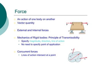
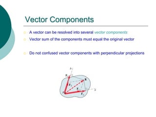
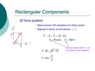
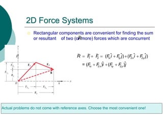
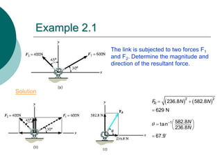
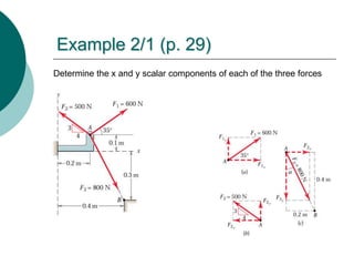
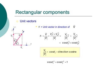
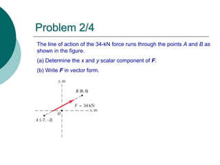
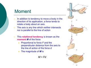
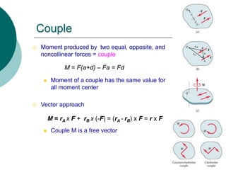
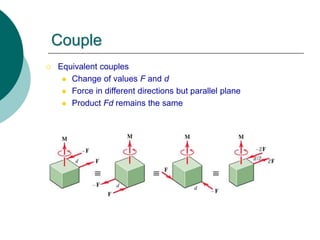
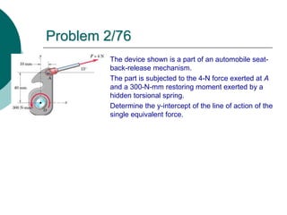
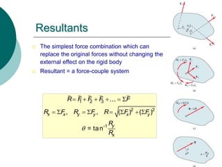
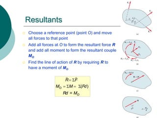
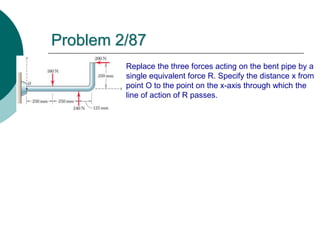
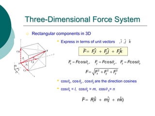
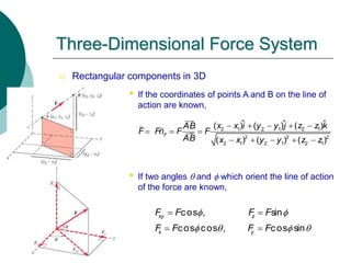
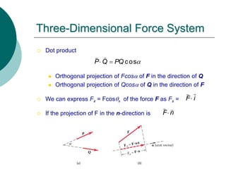
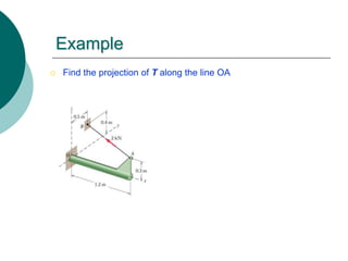
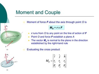
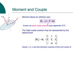
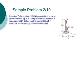
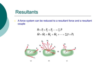
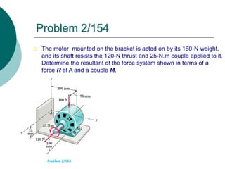
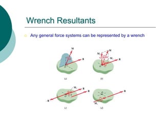
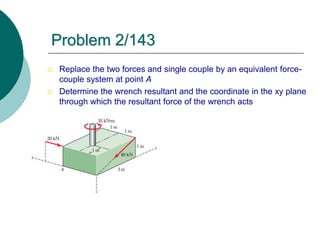
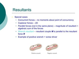
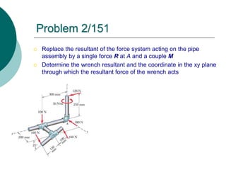
Engineering Mechanics:
Statics
Chapter 2: Force Systems
Force Systems
Part A: Two Dimensional Force Systems
Force
 An action of one body on another
 Vector quantity
 External and Internal forces
 Mechanics of Rigid bodies: Principle of Transmissibility
• Specify magnitude, direction, line of action
• No need to specify point of application
 Concurrent forces
• Lines of action intersect at a point
Vector Components
 A vector can be resolved into several vector components
 Vector sum of the components must equal the original vector
 Do not confused vector components with perpendicular projections
 2D force systems
• Most common 2D resolution of a force vector
• Express in terms of unit vectors ,
Rectangular Components
F
x
y
i
x
F
y
F
j î ˆj
ˆ ˆ
cos , sin
x y x y
x y
F F F Fi F j
F F F F
 
   
 
2 2
x y
F F F F
  

1
tan y
x
F
F
 

Scalar components – can
be positive and negative
2D Force Systems
 Rectangular components are convenient for finding the sum
or resultant of two (or more) forces which are concurrent
R
1 2 1 1 2 2
1 2 1 2
ˆ ˆ ˆ ˆ
( ) ( )
ˆ ˆ
= ( ) ( )
x y x y
x x y y
R F F F i F j F i F j
F F i F F j
     
  
Actual problems do not come with reference axes. Choose the most convenient one!
Example 2.1
 The link is subjected to two forces F1
and F2. Determine the magnitude and
direction of the resultant force.
   
2 2
236.8 582.8
629 N
R
F N N
 

1 582.8
tan
236.8
67.9
N
N
   
  
 

Solution
Example 2/1 (p. 29)
Determine the x and y scalar components of each of the three forces
 Unit vectors
• = Unit vector in direction of
cos direction cosine
x
x
V
V

 
Rectangular components
V
n
x
y
i
x
V
y
V
j
ˆ ˆ
ˆ ˆ
ˆ ˆ
cos cos
x y y
x
x y
V i V j V
V
V
n i j
V V V V
i j
 

   
 
n V
x
y
2 2
cos cos 1
x y
 
 
The line of action of the 34-kN force runs through the points A and B as
shown in the figure.
(a) Determine the x and y scalar component of F.
(b) Write F in vector form.
Problem 2/4
Moment
 In addition to tendency to move a body in the
direction of its application, a force tends to
rotate a body about an axis.
 The axis is any line which neither intersects
nor is parallel to the line of action
 This rotational tendency is known as the
moment M of the force
 Proportional to force F and the
perpendicular distance from the axis to
the line of action of the force d
 The magnitude of M is
M = Fd
Moment
 The moment is a vector M perpendicular to
the plane of the body.
 Sense of M is determined by the right-hand
rule
 Direction of the thumb = arrowhead
 Fingers curled in the direction of the
rotational tendency
 In a given plane (2D),we may speak of
moment about a point which means moment
with respect to an axis normal to the plane
and passing through the point.
 +, - signs are used for moment directions –
must be consistent throughout the problem!
Moment
 A vector approach for moment calculations is
proper for 3D problems.
 Moment of F about point A maybe
represented by the cross-product
where r = a position vector from point A to
any point on the line of action of F
M = r x F
M = Fr sin a = Fd
Example 2/5 (p. 40)
Calculate the magnitude of the moment about
the base point O of the 600-N force by using
both scalar and vector approaches.
Problem 2/50
(a) Calculate the moment of the 90-N force about
point O for the condition  = 15º.
(b) Determine the value of  for which the moment
about O is (b.1) zero (b.2) a maximum
Couple
 Moment produced by two equal, opposite, and
noncollinear forces = couple
 Moment of a couple has the same value for
all moment center
 Vector approach
 Couple M is a free vector
M = F(a+d) – Fa = Fd
M = rA x F + rB x (-F) = (rA - rB) x F = r x F
Couple
 Equivalent couples
 Change of values F and d
 Force in different directions but parallel plane
 Product Fd remains the same
Force-Couple Systems
 Replacement of a force by a force and a couple
 Force F is replaced by a parallel force F and a counterclockwise
couple Fd
Example Replace the force by an equivalent system at point O
Also, reverse the problem by the replacement of
a force and a couple by a single force
Problem 2/76
The device shown is a part of an automobile seat-
back-release mechanism.
The part is subjected to the 4-N force exerted at A
and a 300-N-mm restoring moment exerted by a
hidden torsional spring.
Determine the y-intercept of the line of action of the
single equivalent force.
Resultants
 The simplest force combination which can
replace the original forces without changing the
external effect on the rigid body
 Resultant = a force-couple system
1 2 3
2 2
-1
, , ( ) ( )
= tan
x x y y x y
y
x
R F F F F
R F R F R F F
R
R

     
       
Resultants
 Choose a reference point (point O) and move
all forces to that point
 Add all forces at O to form the resultant force R
and add all moment to form the resultant couple
MO
 Find the line of action of R by requiring R to
have a moment of MO
( )
=
O
O
R F
M M Fd
Rd M
 
   
Problem 2/87
Replace the three forces acting on the bent pipe by a
single equivalent force R. Specify the distance x from
point O to the point on the x-axis through which the
line of action of R passes.
Force Systems
Part B: Three Dimensional Force Systems
 Rectangular components in 3D
• Express in terms of unit vectors , ,
• cosx, cosy , cosz are the direction cosines
• cosx = l, cosy = m, cos z= n
Three-Dimensional Force System
ˆ ˆ ˆ
x y z
F Fi F j Fk
  
2 2 2
x y z
F F F F
  
î ˆj k̂
cos , cos , cos
x x y y z z
F F F F F F
  
  
ˆ ˆ ˆ
( )
F Fli mj nk
  
 Rectangular components in 3D
• If the coordinates of points A and B on the line of
action are known,
• If two angles  and f which orient the line of action
of the force are known,
Three-Dimensional Force System
2 1 2 1 2 1
2 2 2
2 1 2 1 2 1
ˆ ˆ ˆ
( ) ( ) ( )
( ) ( ) ( )
F
x x i y y j z z k
AB
F Fn F F
AB x x y y z z
    
  
    
cos , sin
cos cos , cos sin
xy z
x y
F F F F
F F F F
f f
f  f 
 
 
Problem 2/98
 The cable exerts a tension of 2 kN on the fixed bracket at A.
Write the vector expression for the tension T.
 Dot product
 Orthogonal projection of Fcosa of F in the direction of Q
 Orthogonal projection of Qcosa of Q in the direction of F
 We can express Fx = Fcosx of the force F as Fx =
 If the projection of F in the n-direction is
Three-Dimensional Force System
cos
P Q PQ a
 
F i

F n

Example
 Find the projection of T along the line OA
 Moment of force F about the axis through point O is
 r runs from O to any point on the line of action of F
 Point O and force F establish a plane A
 The vector Mo is normal to the plane in the direction
established by the right-hand rule
 Evaluating the cross product
Moment and Couple
MO = r x F
ˆ ˆ ˆ
O x y z
x y z
i j k
M r r r
F F F

 Moment about an arbitrary axis
known as triple scalar product (see appendix C/7)
 The triple scalar product may be represented by the
determinant
where l, m, n are the direction cosines of the unit vector n
Moment and Couple
( )
M r F n n
   
x y z
x y z
r r r
M M F F F
l m n
 
 
A tension T of magniture 10 kN is applied to the cable
attached to the top A of the rigid mast and secured to
the ground at B. Determine the moment Mz of T
about the z-axis passing through the base O.
Sample Problem 2/10
 A force system can be reduced to a resultant force and a resultant
couple
Resultants
1 2 3
1 2 3 ( )
R F F F F
M M M M r F
    
      
 The motor mounted on the bracket is acted on by its 160-N weight,
and its shaft resists the 120-N thrust and 25-N.m couple applied to it.
Determine the resultant of the force system shown in terms of a
force R at A and a couple M.
Problem 2/154
 Any general force systems can be represented by a wrench
Wrench Resultants
 Replace the two forces and single couple by an equivalent force-
couple system at point A
 Determine the wrench resultant and the coordinate in the xy plane
through which the resultant force of the wrench acts
Problem 2/143
 Special cases
• Concurrent forces – no moments about point of concurrency
• Coplanar forces – 2D
• Parallel forces (not in the same plane) – magnitude of resultant =
algebraic sum of the forces
• Wrench resultant – resultant couple M is parallel to the resultant
force R
• Example of positive wrench = screw driver
Resultants
 Replace the resultant of the force system acting on the pipe
assembly by a single force R at A and a couple M
 Determine the wrench resultant and the coordinate in the xy plane
through which the resultant force of the wrench acts
Problem 2/151

chap2_force_systems - Copy.ppt

  • 1.
  • 2.
    Force Systems Part A:Two Dimensional Force Systems
  • 3.
    Force  An actionof one body on another  Vector quantity  External and Internal forces  Mechanics of Rigid bodies: Principle of Transmissibility • Specify magnitude, direction, line of action • No need to specify point of application  Concurrent forces • Lines of action intersect at a point
  • 4.
    Vector Components  Avector can be resolved into several vector components  Vector sum of the components must equal the original vector  Do not confused vector components with perpendicular projections
  • 5.
     2D forcesystems • Most common 2D resolution of a force vector • Express in terms of unit vectors , Rectangular Components F x y i x F y F j î ˆj ˆ ˆ cos , sin x y x y x y F F F Fi F j F F F F         2 2 x y F F F F     1 tan y x F F    Scalar components – can be positive and negative
  • 6.
    2D Force Systems Rectangular components are convenient for finding the sum or resultant of two (or more) forces which are concurrent R 1 2 1 1 2 2 1 2 1 2 ˆ ˆ ˆ ˆ ( ) ( ) ˆ ˆ = ( ) ( ) x y x y x x y y R F F F i F j F i F j F F i F F j          Actual problems do not come with reference axes. Choose the most convenient one!
  • 7.
    Example 2.1  Thelink is subjected to two forces F1 and F2. Determine the magnitude and direction of the resultant force.     2 2 236.8 582.8 629 N R F N N    1 582.8 tan 236.8 67.9 N N           Solution
  • 8.
    Example 2/1 (p.29) Determine the x and y scalar components of each of the three forces
  • 9.
     Unit vectors •= Unit vector in direction of cos direction cosine x x V V    Rectangular components V n x y i x V y V j ˆ ˆ ˆ ˆ ˆ ˆ cos cos x y y x x y V i V j V V V n i j V V V V i j          n V x y 2 2 cos cos 1 x y    
  • 10.
    The line ofaction of the 34-kN force runs through the points A and B as shown in the figure. (a) Determine the x and y scalar component of F. (b) Write F in vector form. Problem 2/4
  • 11.
    Moment  In additionto tendency to move a body in the direction of its application, a force tends to rotate a body about an axis.  The axis is any line which neither intersects nor is parallel to the line of action  This rotational tendency is known as the moment M of the force  Proportional to force F and the perpendicular distance from the axis to the line of action of the force d  The magnitude of M is M = Fd
  • 12.
    Moment  The momentis a vector M perpendicular to the plane of the body.  Sense of M is determined by the right-hand rule  Direction of the thumb = arrowhead  Fingers curled in the direction of the rotational tendency  In a given plane (2D),we may speak of moment about a point which means moment with respect to an axis normal to the plane and passing through the point.  +, - signs are used for moment directions – must be consistent throughout the problem!
  • 13.
    Moment  A vectorapproach for moment calculations is proper for 3D problems.  Moment of F about point A maybe represented by the cross-product where r = a position vector from point A to any point on the line of action of F M = r x F M = Fr sin a = Fd
  • 14.
    Example 2/5 (p.40) Calculate the magnitude of the moment about the base point O of the 600-N force by using both scalar and vector approaches.
  • 15.
    Problem 2/50 (a) Calculatethe moment of the 90-N force about point O for the condition  = 15º. (b) Determine the value of  for which the moment about O is (b.1) zero (b.2) a maximum
  • 16.
    Couple  Moment producedby two equal, opposite, and noncollinear forces = couple  Moment of a couple has the same value for all moment center  Vector approach  Couple M is a free vector M = F(a+d) – Fa = Fd M = rA x F + rB x (-F) = (rA - rB) x F = r x F
  • 17.
    Couple  Equivalent couples Change of values F and d  Force in different directions but parallel plane  Product Fd remains the same
  • 18.
    Force-Couple Systems  Replacementof a force by a force and a couple  Force F is replaced by a parallel force F and a counterclockwise couple Fd Example Replace the force by an equivalent system at point O Also, reverse the problem by the replacement of a force and a couple by a single force
  • 19.
    Problem 2/76 The deviceshown is a part of an automobile seat- back-release mechanism. The part is subjected to the 4-N force exerted at A and a 300-N-mm restoring moment exerted by a hidden torsional spring. Determine the y-intercept of the line of action of the single equivalent force.
  • 20.
    Resultants  The simplestforce combination which can replace the original forces without changing the external effect on the rigid body  Resultant = a force-couple system 1 2 3 2 2 -1 , , ( ) ( ) = tan x x y y x y y x R F F F F R F R F R F F R R               
  • 21.
    Resultants  Choose areference point (point O) and move all forces to that point  Add all forces at O to form the resultant force R and add all moment to form the resultant couple MO  Find the line of action of R by requiring R to have a moment of MO ( ) = O O R F M M Fd Rd M      
  • 22.
    Problem 2/87 Replace thethree forces acting on the bent pipe by a single equivalent force R. Specify the distance x from point O to the point on the x-axis through which the line of action of R passes.
  • 23.
    Force Systems Part B:Three Dimensional Force Systems
  • 24.
     Rectangular componentsin 3D • Express in terms of unit vectors , , • cosx, cosy , cosz are the direction cosines • cosx = l, cosy = m, cos z= n Three-Dimensional Force System ˆ ˆ ˆ x y z F Fi F j Fk    2 2 2 x y z F F F F    î ˆj k̂ cos , cos , cos x x y y z z F F F F F F       ˆ ˆ ˆ ( ) F Fli mj nk   
  • 25.
     Rectangular componentsin 3D • If the coordinates of points A and B on the line of action are known, • If two angles  and f which orient the line of action of the force are known, Three-Dimensional Force System 2 1 2 1 2 1 2 2 2 2 1 2 1 2 1 ˆ ˆ ˆ ( ) ( ) ( ) ( ) ( ) ( ) F x x i y y j z z k AB F Fn F F AB x x y y z z              cos , sin cos cos , cos sin xy z x y F F F F F F F F f f f  f     
  • 26.
    Problem 2/98  Thecable exerts a tension of 2 kN on the fixed bracket at A. Write the vector expression for the tension T.
  • 27.
     Dot product Orthogonal projection of Fcosa of F in the direction of Q  Orthogonal projection of Qcosa of Q in the direction of F  We can express Fx = Fcosx of the force F as Fx =  If the projection of F in the n-direction is Three-Dimensional Force System cos P Q PQ a   F i  F n 
  • 28.
    Example  Find theprojection of T along the line OA
  • 29.
     Moment offorce F about the axis through point O is  r runs from O to any point on the line of action of F  Point O and force F establish a plane A  The vector Mo is normal to the plane in the direction established by the right-hand rule  Evaluating the cross product Moment and Couple MO = r x F ˆ ˆ ˆ O x y z x y z i j k M r r r F F F 
  • 30.
     Moment aboutan arbitrary axis known as triple scalar product (see appendix C/7)  The triple scalar product may be represented by the determinant where l, m, n are the direction cosines of the unit vector n Moment and Couple ( ) M r F n n     x y z x y z r r r M M F F F l m n    
  • 31.
    A tension Tof magniture 10 kN is applied to the cable attached to the top A of the rigid mast and secured to the ground at B. Determine the moment Mz of T about the z-axis passing through the base O. Sample Problem 2/10
  • 32.
     A forcesystem can be reduced to a resultant force and a resultant couple Resultants 1 2 3 1 2 3 ( ) R F F F F M M M M r F            
  • 33.
     The motormounted on the bracket is acted on by its 160-N weight, and its shaft resists the 120-N thrust and 25-N.m couple applied to it. Determine the resultant of the force system shown in terms of a force R at A and a couple M. Problem 2/154
  • 34.
     Any generalforce systems can be represented by a wrench Wrench Resultants
  • 35.
     Replace thetwo forces and single couple by an equivalent force- couple system at point A  Determine the wrench resultant and the coordinate in the xy plane through which the resultant force of the wrench acts Problem 2/143
  • 36.
     Special cases •Concurrent forces – no moments about point of concurrency • Coplanar forces – 2D • Parallel forces (not in the same plane) – magnitude of resultant = algebraic sum of the forces • Wrench resultant – resultant couple M is parallel to the resultant force R • Example of positive wrench = screw driver Resultants
  • 37.
     Replace theresultant of the force system acting on the pipe assembly by a single force R at A and a couple M  Determine the wrench resultant and the coordinate in the xy plane through which the resultant force of the wrench acts Problem 2/151