Downloaded 417 times
![PROPRIETARY MATERIAL. © 2010 The McGraw-Hill Companies, Inc. All rights reserved. No part of this Manual may be displayed,
reproduced or distributed in any form or by any means, without the prior written permission of the publisher, or used beyond the limited
distribution to teachers and educators permitted by McGraw-Hill for their individual course preparation. If you are a student using this Manual,
you are using it without permission.
51
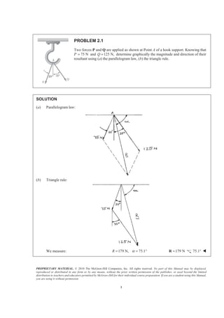
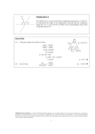
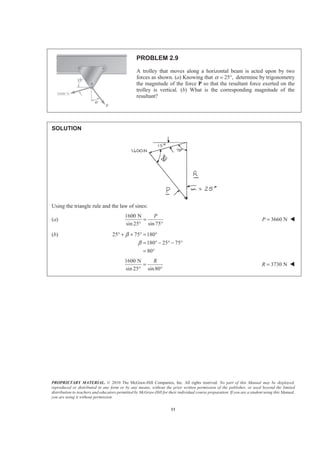
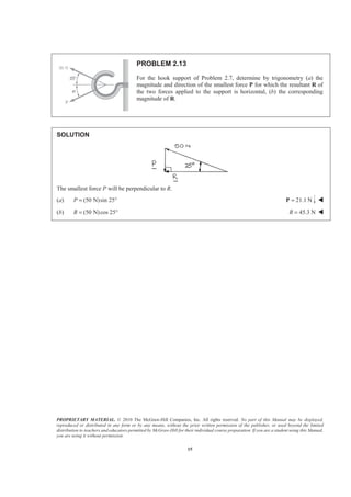
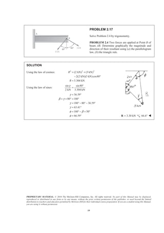
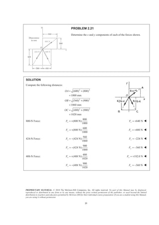
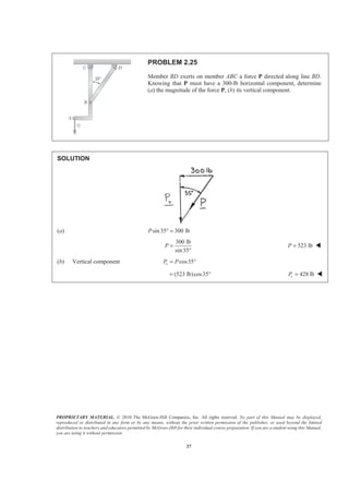
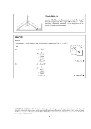
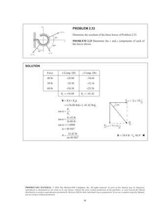
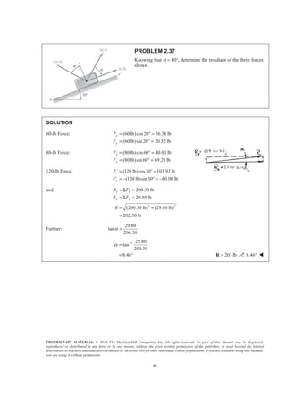
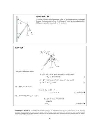
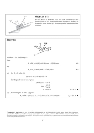
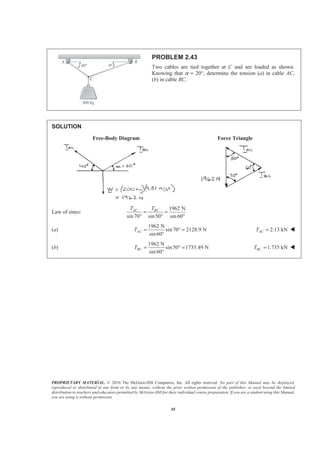
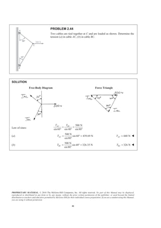
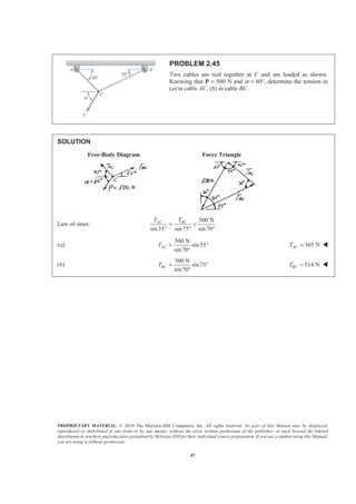
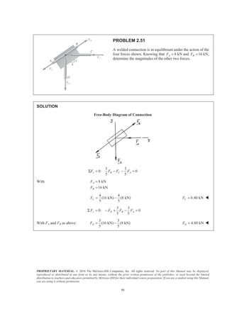
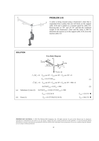
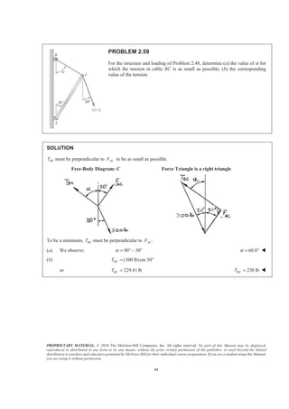
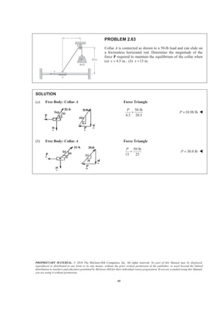
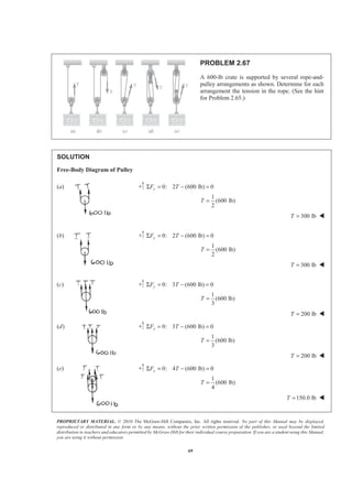
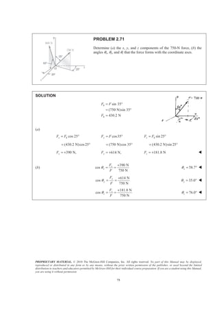
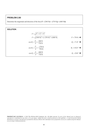
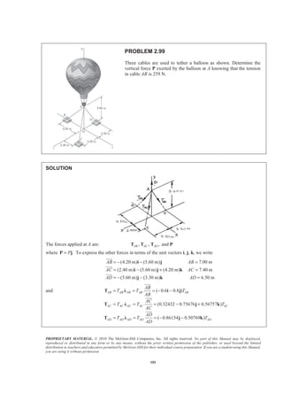
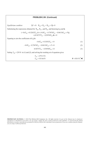
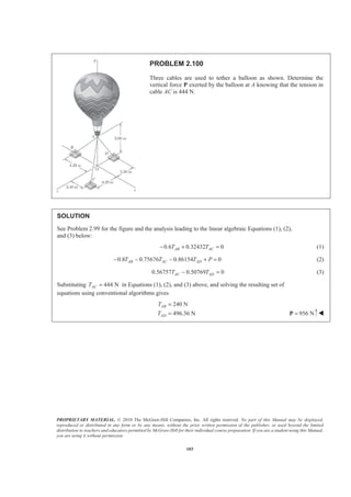
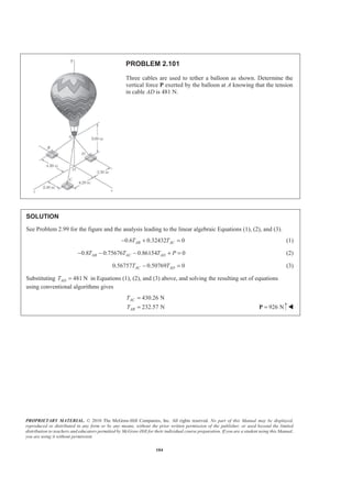
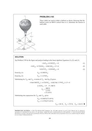
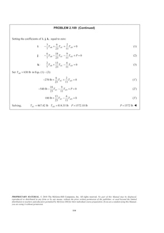
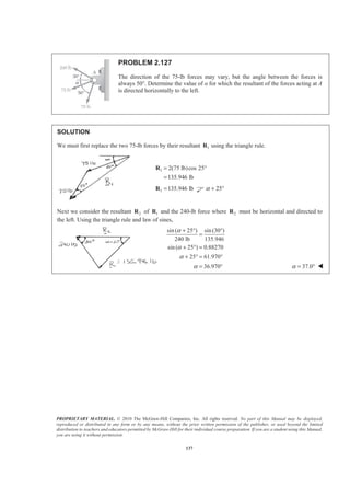
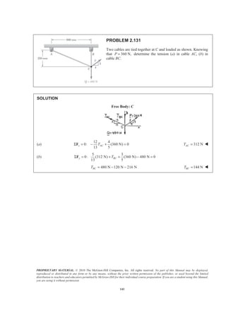
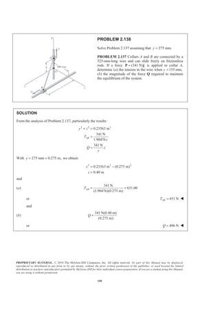
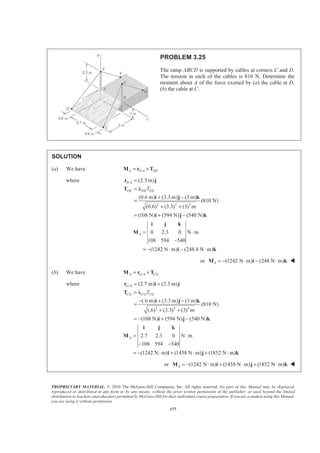
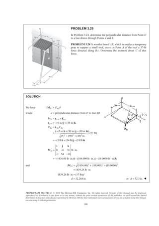
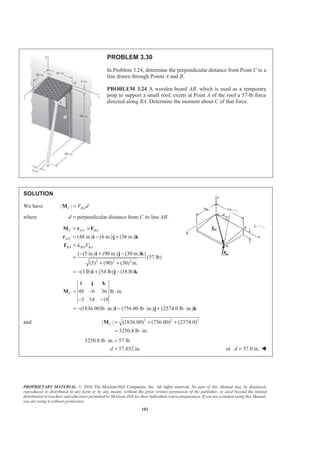
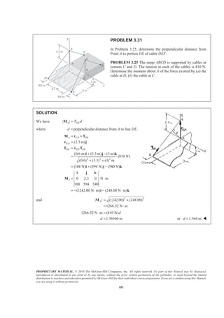
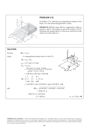
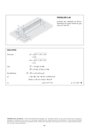
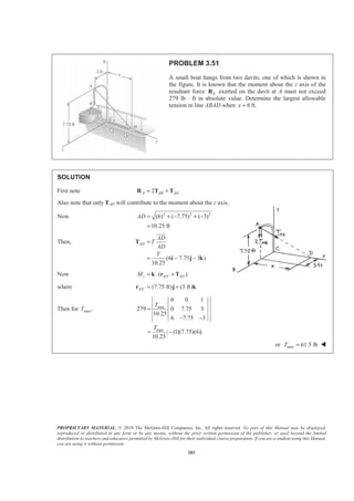
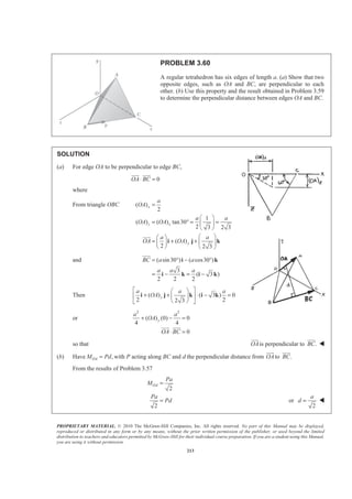
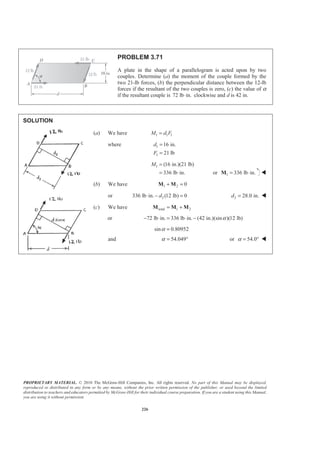
PROBLEM 2.49
Two forces P and Q are applied as shown to an aircraft
connection. Knowing that the connection is in equilibrium and
that 500P = lb and 650Q = lb, determine the magnitudes of
the forces exerted on the rods A and B.
SOLUTION
Free-Body Diagram
Resolving the forces into x- and y-directions:
0A B= + + + =R P Q F F
Substituting components: (500 lb) [(650 lb)cos50 ]
[(650 lb)sin50 ]
( cos50 ) ( sin50 ) 0B A AF F F
= − + °
− °
+ − ° + ° =
R j i
j
i i j
In the y-direction (one unknown force)
500 lb (650 lb)sin50 sin50 0AF− − ° + ° =
Thus,
500 lb (650 lb)sin50
sin50
AF
+ °
=
°
1302.70 lb= 1303 lbAF = W
In the x-direction: (650 lb)cos50 cos50 0B AF F° + − ° =
Thus, cos50 (650 lb)cos50
(1302.70 lb)cos50 (650 lb)cos50
B AF F= ° − °
= ° − °
419.55 lb= 420 lbBF = W](https://image.slidesharecdn.com/mecanica-151208044028-lva1-app6892/85/Mecanica-49-320.jpg)
![PROPRIETARY MATERIAL. © 2010 The McGraw-Hill Companies, Inc. All rights reserved. No part of this Manual may be displayed,
reproduced or distributed in any form or by any means, without the prior written permission of the publisher, or used beyond the limited
distribution to teachers and educators permitted by McGraw-Hill for their individual course preparation. If you are a student using this Manual,
you are using it without permission.
52
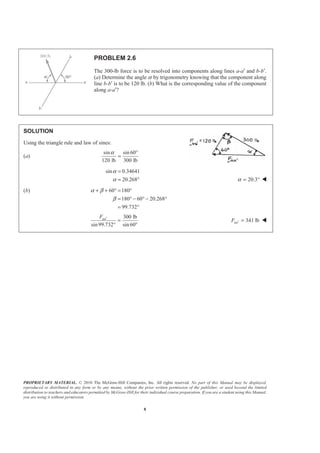
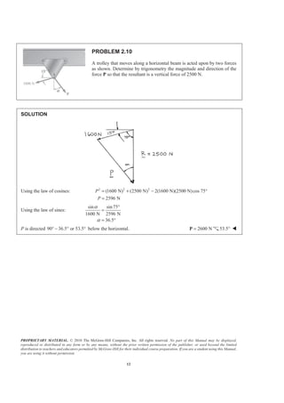
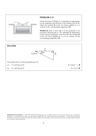
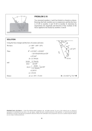
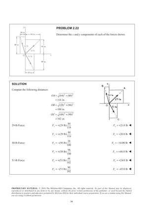
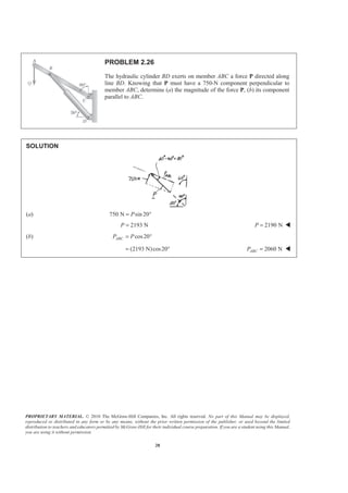
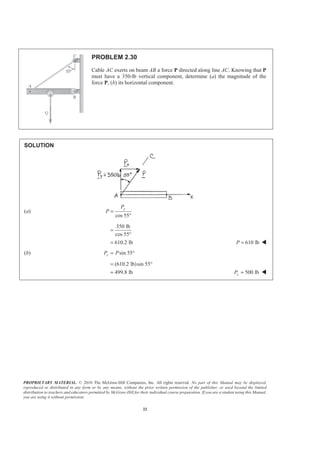
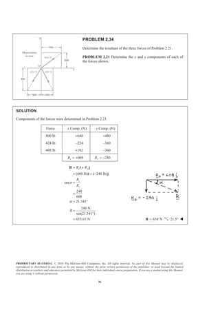
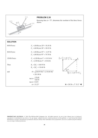
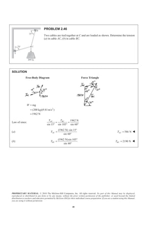
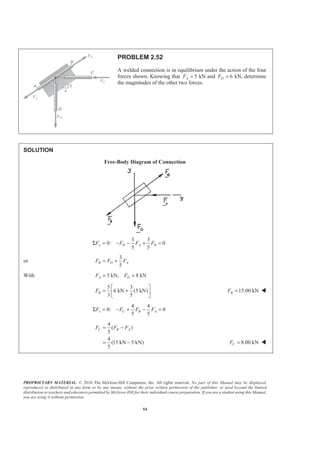
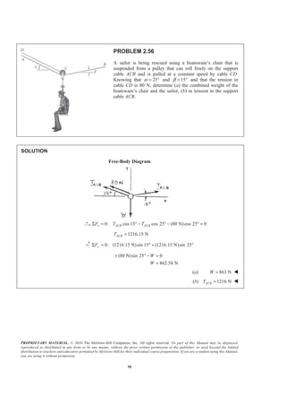
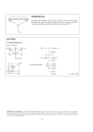
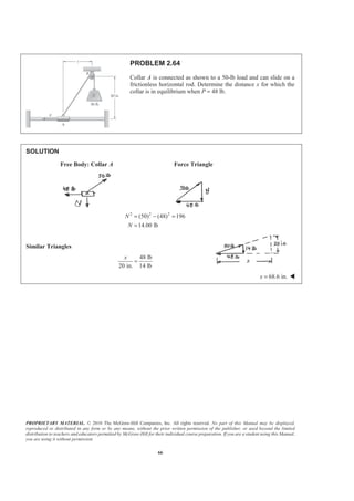
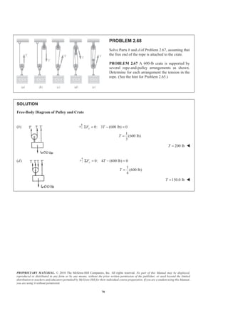
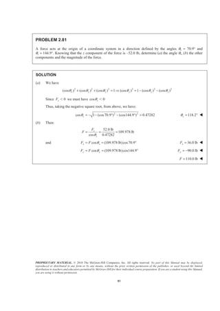
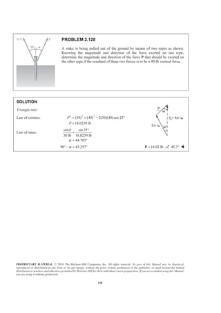
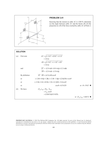
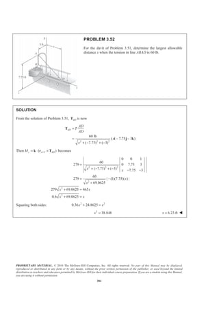
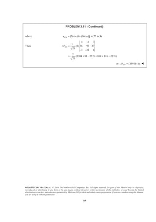
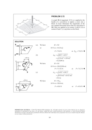
PROBLEM 2.50
Two forces P and Q are applied as shown to an aircraft
connection. Knowing that the connection is in equilibrium
and that the magnitudes of the forces exerted on rods A and B
are 750AF = lb and 400BF = lb, determine the magnitudes of
P and Q.
SOLUTION
Free-Body Diagram
Resolving the forces into x- and y-directions:
0A B= + + + =R P Q F F
Substituting components: cos 50 sin 50
[(750 lb)cos 50 ]
[(750 lb)sin 50 ] (400 lb)
P Q Q= − + ° − °
− °
+ ° +
R j i j
i
j i
In the x-direction (one unknown force)
cos 50 [(750 lb)cos 50 ] 400 lb 0Q ° − ° + =
(750 lb)cos 50 400 lb
cos 50
127.710 lb
Q
° −
=
°
=
In the y-direction: sin 50 (750 lb)sin 50 0P Q− − ° + ° =
sin 50 (750 lb)sin 50
(127.710 lb)sin 50 (750 lb)sin 50
476.70 lb
P Q= − ° + °
= − ° + °
= 477 lb; 127.7 lbP Q= = W](https://image.slidesharecdn.com/mecanica-151208044028-lva1-app6892/85/Mecanica-50-320.jpg)

![PROPRIETARY MATERIAL. © 2010 The McGraw-Hill Companies, Inc. All rights reserved. No part of this Manual may be displayed,
reproduced or distributed in any form or by any means, without the prior written permission of the publisher, or used beyond the limited
distribution to teachers and educators permitted by McGraw-Hill for their individual course preparation. If you are a student using this Manual,
you are using it without permission.
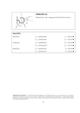
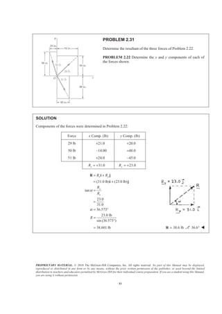
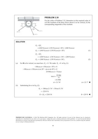
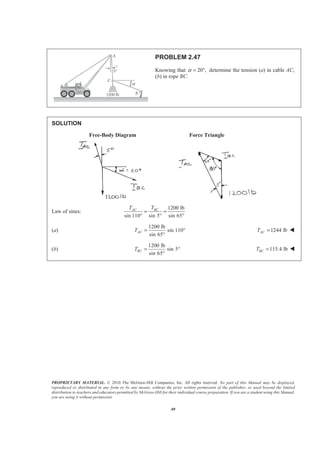
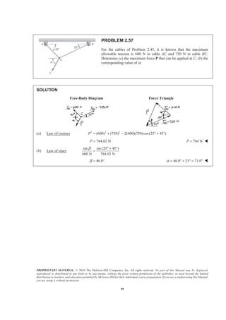
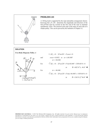
87
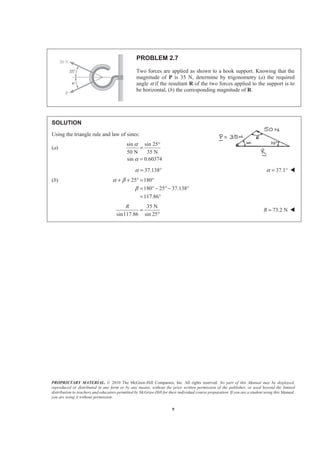
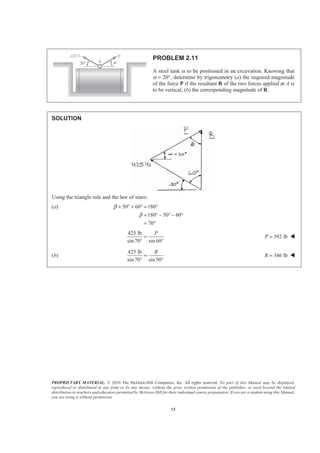
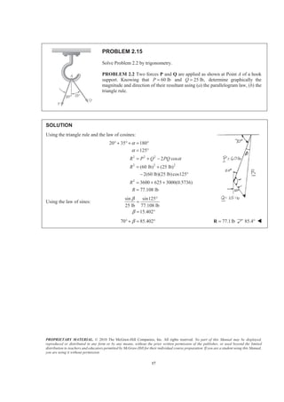
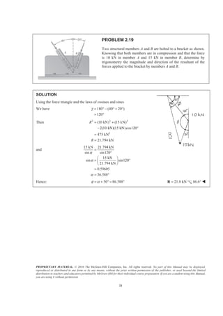
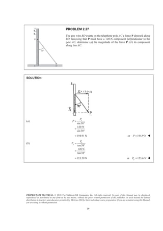
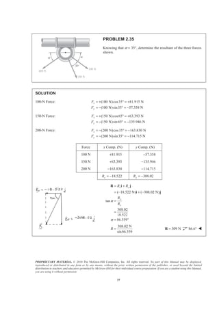
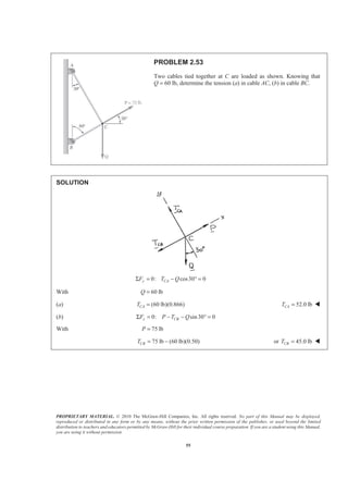
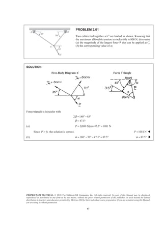
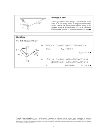
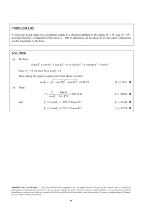
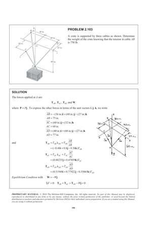
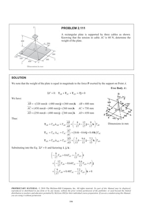
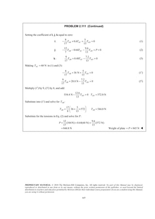
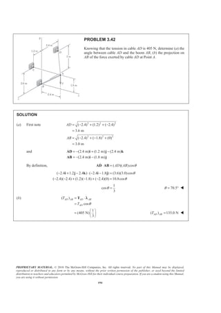
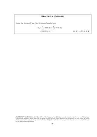
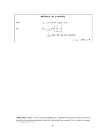
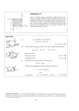
PROBLEM 2.85
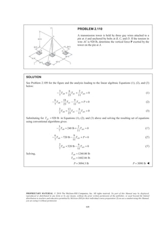
A transmission tower is held by three guy wires anchored by bolts
at B, C, and D. If the tension in wire AB is 525 lb, determine the
components of the force exerted by the wire on the bolt at B.
SOLUTION
2 2 2
(20 ft) (100 ft) (25 ft)
(20 ft) (100 ft) ( 25 ft)
105 ft
525 lb
[(20 ft) (100 ft) (25 ft) ]
105 ft
(100.0 lb) (500 lb) (125.0 lb)
BA
BA
BA
F
BA
F
BA
= + −
= + + −
=
=
=
= + −
= + −
i j k
F Ȝ
i j k
F i j k
JJJG
JJJG
100.0 lb, 500 lb, 125.0 lbx y zF F F= + = + = − W](https://image.slidesharecdn.com/mecanica-151208044028-lva1-app6892/85/Mecanica-85-320.jpg)
![PROPRIETARY MATERIAL. © 2010 The McGraw-Hill Companies, Inc. All rights reserved. No part of this Manual may be displayed,
reproduced or distributed in any form or by any means, without the prior written permission of the publisher, or used beyond the limited
distribution to teachers and educators permitted by McGraw-Hill for their individual course preparation. If you are a student using this Manual,
you are using it without permission.
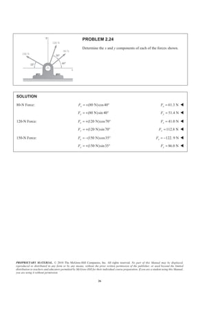
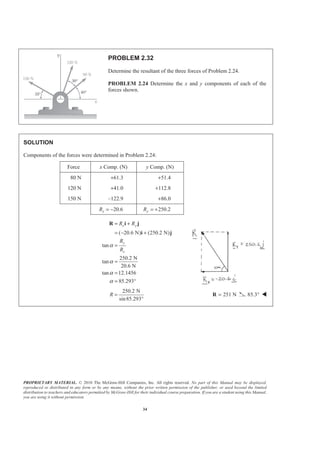
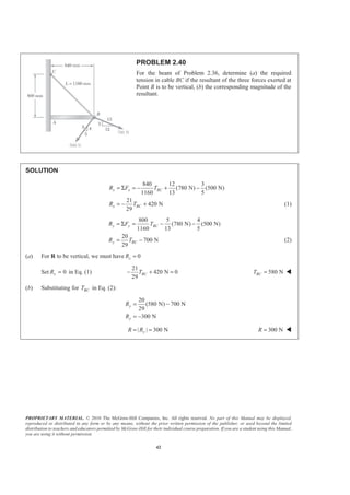
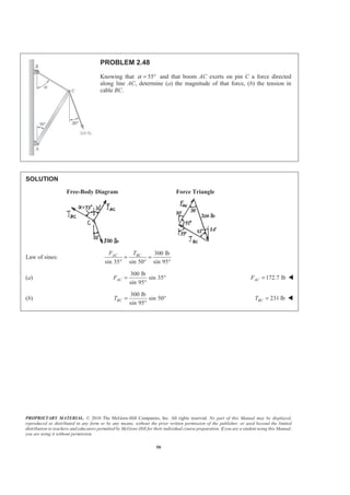
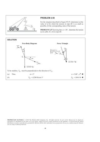
88
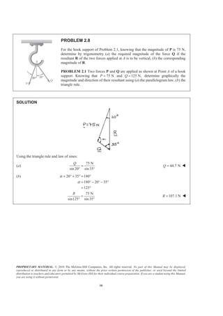
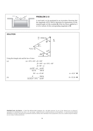
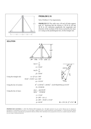
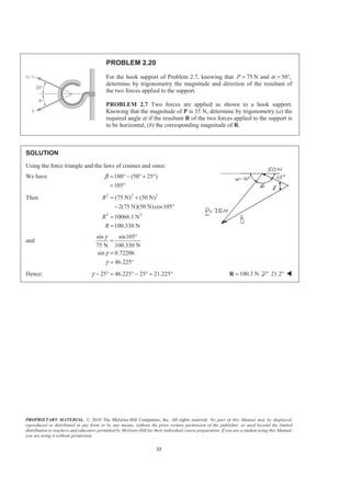
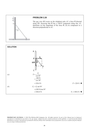
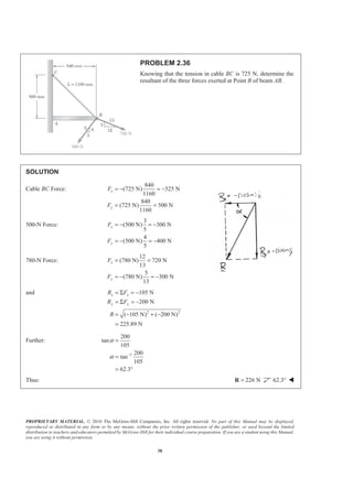
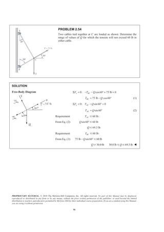
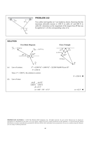
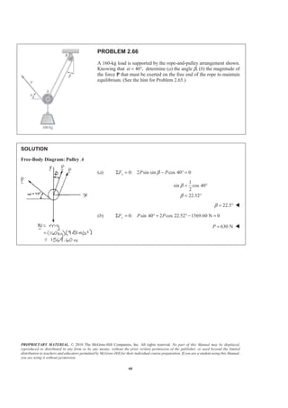
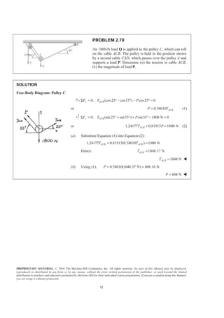
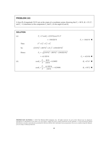
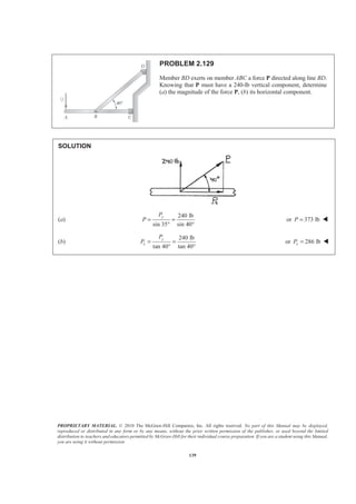
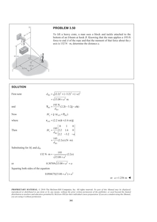
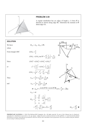
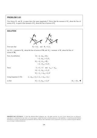
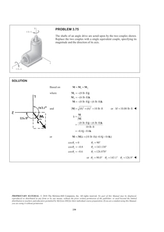
PROBLEM 2.86
A transmission tower is held by three guy wires anchored by bolts
at B, C, and D. If the tension in wire AD is 315 lb, determine the
components of the force exerted by the wire on the bolt at D.
SOLUTION
2 2 2
(20 ft) (100 ft) (70 ft)
(20 ft) (100 ft) ( 70 ft)
126 ft
315 lb
[(20 ft) (100 ft) (74 ft) ]
126 ft
(50 lb) (250 lb) (185 lb)
DA
DA
DA
F
DA
F
DA
= + +
= + + +
=
=
=
= + +
= + +
i j k
F Ȝ
i j k
F i j k
JJJG
JJJG
50 lb, 250 lb, 185.0 lbx y zF F F= + = + = + W](https://image.slidesharecdn.com/mecanica-151208044028-lva1-app6892/85/Mecanica-86-320.jpg)
![PROPRIETARY MATERIAL. © 2010 The McGraw-Hill Companies, Inc. All rights reserved. No part of this Manual may be displayed,
reproduced or distributed in any form or by any means, without the prior written permission of the publisher, or used beyond the limited
distribution to teachers and educators permitted by McGraw-Hill for their individual course preparation. If you are a student using this Manual,
you are using it without permission.
89
PROBLEM 2.87
A frame ABC is supported in part by cable DBE that passes
through a frictionless ring at B. Knowing that the tension in the
cable is 385 N, determine the components of the force exerted by
the cable on the support at D.
SOLUTION
2 2 2
(480 mm) (510 mm) (320 mm)
(480 mm) (510 mm ) (320 mm)
770 mm
385 N
[(480 mm) (510 mm) (320 mm) ]
770 mm
(240 N) (255 N) (160 N)
DB
DB
DB
F
DB
F
DB
= − +
= + +
=
=
=
= − +
= − +
i j k
F Ȝ
i j k
i j k
JJJG
JJJG
240 N, 255 N, 160.0 Nx y zF F F= + = − = + W](https://image.slidesharecdn.com/mecanica-151208044028-lva1-app6892/85/Mecanica-87-320.jpg)
![PROPRIETARY MATERIAL. © 2010 The McGraw-Hill Companies, Inc. All rights reserved. No part of this Manual may be displayed,
reproduced or distributed in any form or by any means, without the prior written permission of the publisher, or used beyond the limited
distribution to teachers and educators permitted by McGraw-Hill for their individual course preparation. If you are a student using this Manual,
you are using it without permission.
90
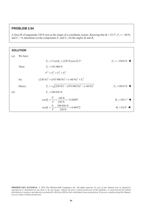
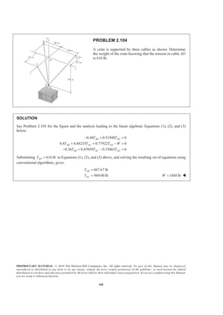
PROBLEM 2.88
For the frame and cable of Problem 2.87, determine the components
of the force exerted by the cable on the support at E.
PROBLEM 2.87 A frame ABC is supported in part by cable DBE
that passes through a frictionless ring at B. Knowing that the tension
in the cable is 385 N, determine the components of the force exerted
by the cable on the support at D.
SOLUTION
2 2 2
(270 mm) (400 mm) (600 mm)
(270 mm) (400 mm) (600 mm)
770 mm
385 N
[(270 mm) (400 mm) (600 mm) ]
770 mm
(135 N) (200 N) (300 N)
EB
EB
EB
F
EB
F
EB
= − +
= + +
=
=
=
= − +
= − +
i j k
F Ȝ
i j k
F i j k
JJJG
JJJG
135.0 N, 200 N, 300 Nx y zF F F= + = − = + W](https://image.slidesharecdn.com/mecanica-151208044028-lva1-app6892/85/Mecanica-88-320.jpg)
![PROPRIETARY MATERIAL. © 2010 The McGraw-Hill Companies, Inc. All rights reserved. No part of this Manual may be displayed,
reproduced or distributed in any form or by any means, without the prior written permission of the publisher, or used beyond the limited
distribution to teachers and educators permitted by McGraw-Hill for their individual course preparation. If you are a student using this Manual,
you are using it without permission.
91
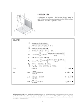
PROBLEM 2.89
Knowing that the tension in cable AB is 1425 N, determine the
components of the force exerted on the plate at B.
SOLUTION
2 2 2
(900 mm) (600 mm) (360 mm)
(900 mm) (600 mm) (360 mm)
1140 mm
1425 N
[ (900 mm) (600 mm) (360 mm) ]
1140 mm
(1125 N) (750 N) (450 N)
BA BA BA
BA
BA
BA
BA
T
BA
T
BA
= − + +
= + +
=
=
=
= − + +
= − + +
i j k
T Ȝ
T i j k
i j k
JJJG
JJJG
( ) 1125 N, ( ) 750 N, ( ) 450 NBA x BA y BA zT T T= − = = W](https://image.slidesharecdn.com/mecanica-151208044028-lva1-app6892/85/Mecanica-89-320.jpg)
![PROPRIETARY MATERIAL. © 2010 The McGraw-Hill Companies, Inc. All rights reserved. No part of this Manual may be displayed,
reproduced or distributed in any form or by any means, without the prior written permission of the publisher, or used beyond the limited
distribution to teachers and educators permitted by McGraw-Hill for their individual course preparation. If you are a student using this Manual,
you are using it without permission.
92
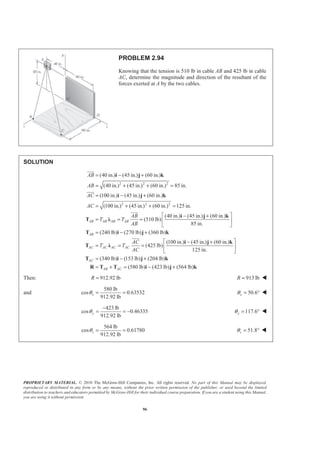
PROBLEM 2.90
Knowing that the tension in cable AC is 2130 N, determine the
components of the force exerted on the plate at C.
SOLUTION
2 2 2
(900 mm) (600 mm) (920 mm)
(900 mm) (600 mm) (920 mm)
1420 mm
2130 N
[ (900 mm) (600 mm) (920 mm) ]
1420 mm
(1350 N) (900 N) (1380 N)
CA CA CA
CA
CA
CA
CA
T
CA
T
CA
λ
= − + −
= + +
=
=
=
= − + −
= − + −
i j k
T
T i j k
i j k
JJJG
JJJG
( ) 1350 N, ( ) 900 N, ( ) 1380 NCA x CA y CA zT T T= − = = − W](https://image.slidesharecdn.com/mecanica-151208044028-lva1-app6892/85/Mecanica-90-320.jpg)
![PROPRIETARY MATERIAL. © 2010 The McGraw-Hill Companies, Inc. All rights reserved. No part of this Manual may be displayed,
reproduced or distributed in any form or by any means, without the prior written permission of the publisher, or used beyond the limited
distribution to teachers and educators permitted by McGraw-Hill for their individual course preparation. If you are a student using this Manual,
you are using it without permission.
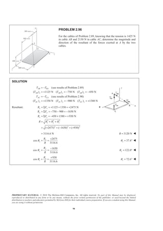
93
PROBLEM 2.91
Find the magnitude and direction of the resultant of the two forces
shown knowing that P = 300 N and Q = 400 N.
SOLUTION
(300 N)[ cos30 sin15 sin30 cos30 cos15 ]
(67.243 N) (150 N) (250.95 N)
(400 N)[cos50 cos20 sin50 cos50 sin 20 ]
(400 N)[0.60402 0.76604 0.21985]
(241.61 N) (306.42 N) (87.939 N)
(174.
= − ° ° + ° + ° °
= − + +
= ° ° + ° − ° °
= + −
= + −
= +
=
P i j k
i j k
Q i j k
i j
i j k
R P Q
2 2 2
367 N) (456.42 N) (163.011 N)
(174.367 N) (456.42 N) (163.011 N)
515.07 N
R
+ +
= + +
=
i j k
515 NR = W
174.367 N
cos 0.33853
515.07 N
x
x
R
R
θ = = = 70.2xθ = ° W
456.42 N
cos 0.88613
515.07 N
y
y
R
R
θ = = = 27.6yθ = ° W
163.011 N
cos 0.31648
515.07 N
z
z
R
R
θ = = = 71.5zθ = ° W](https://image.slidesharecdn.com/mecanica-151208044028-lva1-app6892/85/Mecanica-91-320.jpg)
![PROPRIETARY MATERIAL. © 2010 The McGraw-Hill Companies, Inc. All rights reserved. No part of this Manual may be displayed,
reproduced or distributed in any form or by any means, without the prior written permission of the publisher, or used beyond the limited
distribution to teachers and educators permitted by McGraw-Hill for their individual course preparation. If you are a student using this Manual,
you are using it without permission.
94
PROBLEM 2.92
Find the magnitude and direction of the resultant of the two forces
shown knowing that P = 400 N and Q = 300 N.
SOLUTION
(400 N)[ cos30 sin15 sin30 cos30 cos15 ]
(89.678 N) (200 N) (334.61 N)
(300 N)[cos50 cos20 sin50 cos50 sin 20 ]
(181.21 N) (229.81 N) (65.954 N)
(91.532 N) (429.81 N) (268.66 N)
(91.5R
= − ° ° + ° + ° °
= − + +
= ° ° + ° − ° °
= + −
= +
= + +
=
P i j k
i j k
Q i j k
i j k
R P Q
i j k
2 2 2
32 N) (429.81 N) (268.66 N)
515.07 N
+ +
= 515 NR = W
91.532 N
cos 0.177708
515.07 N
x
x
R
R
θ = = = 79.8xθ = ° W
429.81 N
cos 0.83447
515.07 N
y
y
R
R
θ = = = 33.4yθ = ° W
268.66 N
cos 0.52160
515.07 N
z
z
R
R
θ = = = 58.6zθ = ° W](https://image.slidesharecdn.com/mecanica-151208044028-lva1-app6892/85/Mecanica-92-320.jpg)
![PROPRIETARY MATERIAL. © 2010 The McGraw-Hill Companies, Inc. All rights reserved. No part of this Manual may be displayed,
reproduced or distributed in any form or by any means, without the prior written permission of the publisher, or used beyond the limited
distribution to teachers and educators permitted by McGraw-Hill for their individual course preparation. If you are a student using this Manual,
you are using it without permission.
97
PROBLEM 2.95
For the frame of Problem 2.87, determine the magnitude and
direction of the resultant of the forces exerted by the cable at B
knowing that the tension in the cable is 385 N.
PROBLEM 2.87 A frame ABC is supported in part by cable
DBE that passes through a frictionless ring at B. Knowing that
the tension in the cable is 385 N, determine the components of
the force exerted by the cable on the support at D.
SOLUTION
2 2 2
(480 mm) (510 mm) (320 mm)
(480 mm) (510 mm) (320 mm) 770 mm
BD
BD
= − + −
= + + =
i j k
JJJG
(385 N)
[ (480 mm) (510 mm) (320 mm) ]
(770 mm)
(240 N) (255 N) (160 N)
BD BD BD BD
BD
T T
BD
= =
= − + −
= − + −
F Ȝ
i j k
i j k
JJJG
2 2 2
(270 mm) (400 mm) (600 mm)
(270 mm) (400 mm) (600 mm) 770 mm
BE
BE
= − + −
= + + =
i j k
JJJG
(385 N)
[ (270 mm) (400 mm) (600 mm) ]
(770 mm)
(135 N) (200 N) (300 N)
BE BE BE BE
BE
T T
BE
= =
= − + −
= − + −
F Ȝ
i j k
i j k
JJJG
(375 N) (455 N) (460 N)BD BE= + = − + −R F F i j k
2 2 2
(375 N) (455 N) (460 N) 747.83 NR = + + = 748 NR = W
375 N
cos
747.83 N
xθ
−
= 120.1xθ = ° W
455 N
cos
747.83 N
yθ = 52.5yθ = ° W
460 N
cos
747.83 N
zθ
−
= 128.0zθ = ° W](https://image.slidesharecdn.com/mecanica-151208044028-lva1-app6892/85/Mecanica-95-320.jpg)
![PROPRIETARY MATERIAL. © 2010 The McGraw-Hill Companies, Inc. All rights reserved. No part of this Manual may be displayed,
reproduced or distributed in any form or by any means, without the prior written permission of the publisher, or used beyond the limited
distribution to teachers and educators permitted by McGraw-Hill for their individual course preparation. If you are a student using this Manual,
you are using it without permission.
99
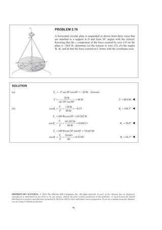
PROBLEM 2.97
The end of the coaxial cable AE is attached to the pole AB, which
is strengthened by the guy wires AC and AD. Knowing that the
tension in AC is 150 lb and that the resultant of the forces exerted
at A by wires AC and AD must be contained in the xy plane,
determine (a) the tension in AD, (b) the magnitude and direction
of the resultant of the two forces.
SOLUTION
(150 lb)(cos 60 cos 20 sin 60 cos 60 sin 20 )
(sin 36 sin 48 cos 36 sin 36 cos 48 )
AC AD
ADT
= +
= ° ° − ° − ° °
+ ° ° − ° + ° °
R T T
i j k
i j k (1)
(a) Since 0,zR = The coefficient of k must be zero.
(150 lb)( cos 60 sin 20 ) (sin 36 cos 48 ) 0
65.220 lb
AD
AD
T
T
− ° ° + ° ° =
= 65.2 lbADT = W
(b) Substituting for ADT into Eq. (1) gives:
[(150 lb) cos 60 cos 20 (65.220 lb)sin 36 sin 48 )]
[(150 lb)sin 60 (65.220 lb)cos 36 ] 0
= ° ° + ° °
− ° + ° +
R i
j
2 2
(98.966 lb) (182.668 lb)
(98.966 lb) (182.668 lb)
207.76 lb
R
= −
= +
=
R i j
208 lbR = W
98.966 lb
cos
207.76 lb
xθ = 61.6xθ = ° W
182.668 lb
cos
207.76 lb
yθ = 151.6yθ = ° W
cos 0zθ = 90.0zθ = ° W](https://image.slidesharecdn.com/mecanica-151208044028-lva1-app6892/85/Mecanica-97-320.jpg)
![PROPRIETARY MATERIAL. © 2010 The McGraw-Hill Companies, Inc. All rights reserved. No part of this Manual may be displayed,
reproduced or distributed in any form or by any means, without the prior written permission of the publisher, or used beyond the limited
distribution to teachers and educators permitted by McGraw-Hill for their individual course preparation. If you are a student using this Manual,
you are using it without permission.
100
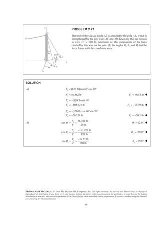
PROBLEM 2.98
The end of the coaxial cable AE is attached to the pole AB, which
is strengthened by the guy wires AC and AD. Knowing that the
tension in AD is 125 lb and that the resultant of the forces exerted
at A by wires AC and AD must be contained in the xy plane,
determine (a) the tension in AC, (b) the magnitude and direction
of the resultant of the two forces.
SOLUTION
(cos 60 cos 20 sin 60 cos 60 sin 20 )
(125 lb)(sin 36 sin 48 cos 36 sin 36 cos 48 )
AC AD
ACT
= +
= ° ° − ° − ° °
+ ° ° − ° + ° °
R T T
i j k
i j k (1)
(a) Since 0,zR = The coefficient of k must be zero.
( cos 60 sin 20 ) (125 lb)(sin 36 cos 48 ) 0
287.49 lb
AC
AC
T
T
− ° ° + ° ° =
= 287 lbACT = W
(b) Substituting for ACT into Eq. (1) gives:
[(287.49 lb) cos 60 cos 20 (125 lb)sin 36 sin 48 ]
[(287.49 lb)sin 60 (125 lb)cos 36 ] 0
= ° ° + ° °
− ° + ° +
R i
j
2 2
(189.677 lb) (350.10 lb)
(189.677 lb) (350.10 lb)
398.18 lb
R
= −
= +
=
R i j
398 lbR = W
189.677 lb
cos
398.18 lb
xθ = 61.6xθ = ° W
350.10 lb
cos
398.18 lb
yθ = 151.6yθ = ° W
cos 0zθ = 90.0zθ = ° W](https://image.slidesharecdn.com/mecanica-151208044028-lva1-app6892/85/Mecanica-98-320.jpg)
![PROPRIETARY MATERIAL. © 2010 The McGraw-Hill Companies, Inc. All rights reserved. No part of this Manual may be displayed,
reproduced or distributed in any form or by any means, without the prior written permission of the publisher, or used beyond the limited
distribution to teachers and educators permitted by McGraw-Hill for their individual course preparation. If you are a student using this Manual,
you are using it without permission.
111
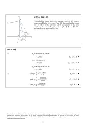
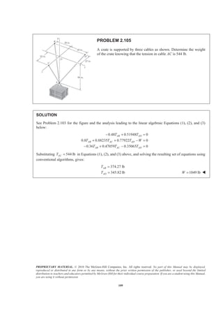
PROBLEM 2.107
Three cables are connected at A, where the forces P and Q are
applied as shown. Knowing that 0,Q = find the value of P for
which the tension in cable AD is 305 N.
SOLUTION
0: 0A AB AC ADΣ = + + + =F T T T P where P=P i
(960 mm) (240 mm) (380 mm) 1060 mm
(960 mm) (240 mm) (320 mm) 1040 mm
(960 mm) (720 mm) (220 mm) 1220 mm
AB AB
AC AC
AD AD
= − − + =
= − − − =
= − + − =
i j k
i j k
i j k
JJJG
JJJG
JJJG
48 12 19
53 53 53
12 3 4
13 13 13
305 N
[( 960 mm) (720 mm) (220 mm) ]
1220 mm
(240 N) (180 N) (55 N)
AB AB AB AB AB
AC AC AC AC AC
AD AD AD
AB
T T T
AB
AC
T T T
AC
T
§ ·
= = = − − +¨ ¸
© ¹
§ ·
= = = − − −¨ ¸
© ¹
= = − + −
= − + −
T Ȝ i j k
T Ȝ i j k
T Ȝ i j k
i j k
JJJG
JJJG
Substituting into 0,AΣ =F factoring , , ,i j k and setting each coefficient equal to φ gives:
48 12
: 240 N
53 13
AB ACP T T= + +i (1)
:j
12 3
180 N
53 13
AB ACT T+ = (2)
:k
19 4
55 N
53 13
AB ACT T− = (3)
Solving the system of linear equations using conventional algorithms gives:
446.71 N
341.71 N
AB
AC
T
T
=
= 960 NP = W](https://image.slidesharecdn.com/mecanica-151208044028-lva1-app6892/85/Mecanica-109-320.jpg)
![PROPRIETARY MATERIAL. © 2010 The McGraw-Hill Companies, Inc. All rights reserved. No part of this Manual may be displayed,
reproduced or distributed in any form or by any means, without the prior written permission of the publisher, or used beyond the limited
distribution to teachers and educators permitted by McGraw-Hill for their individual course preparation. If you are a student using this Manual,
you are using it without permission.
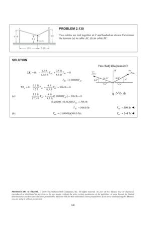
126
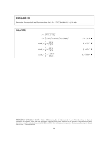
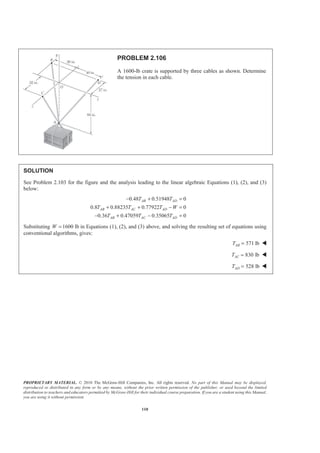
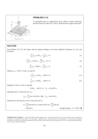
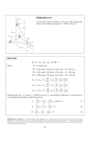
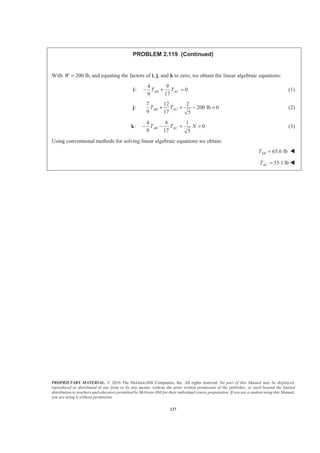
PROBLEM 2.119
Using two ropes and a roller chute, two workers are unloading a 200-lb
cast-iron counterweight from a truck. Knowing that at the instant
shown the counterweight is kept from moving and that the positions of
Points A, B, and C are, respectively, A(0, –20 in., 40 in.), B(–40 in.,
50 in., 0), and C(45 in., 40 in., 0), and assuming that no friction exists
between the counterweight and the chute, determine the tension in each
rope. (Hint: Since there is no friction, the force exerted by the chute on
the counterweight must be perpendicular to the chute.)
SOLUTION
From the geometry of the chute:
(2 )
5
(0.8944 0.4472 )
N
N
= +
= +
N j k
j k
The force in each rope can be written as the product of the magnitude of the
force and the unit vector along the cable. Thus, with
2 2 2
(40 in.) (70 in.) (40 in.)
(40 in.) (70 in.) (40 in.)
90 in.
[( 40 in.) (70 in.) (40 in.) ]
90 in.
4 7 4
9 9 9
AB AB AB
AB
AB AB
AB
AB
AB
T T
AB
T
T
= + −
= + +
=
= =
= − + −
§ ·
= − + −¨ ¸
© ¹
i j k
T Ȝ
i j k
T i j k
JJJG
JJJG
and
2 2 2
(45 in.) (60 in.) (40 in.)
(45 in.) (60 in.) (40 in.) 85 in.
AC
AC
= + −
= + + =
i j k
JJJG
[(45 in.) (60 in.) (40 in.) ]
85 in.
9 12 8
17 17 17
AC AC AC
AC
AC AC
AC
T T
AC
T
T
= =
= + −
§ ·
= + −¨ ¸
© ¹
T Ȝ
i j k
T i j k
JJJG
Then: 0: 0AB ACΣ = + + + =F N T T W](https://image.slidesharecdn.com/mecanica-151208044028-lva1-app6892/85/Mecanica-124-320.jpg)
![PROPRIETARY MATERIAL. © 2010 The McGraw-Hill Companies, Inc. All rights reserved. No part of this Manual may be displayed,
reproduced or distributed in any form or by any means, without the prior written permission of the publisher, or used beyond the limited
distribution to teachers and educators permitted by McGraw-Hill for their individual course preparation. If you are a student using this Manual,
you are using it without permission.
132
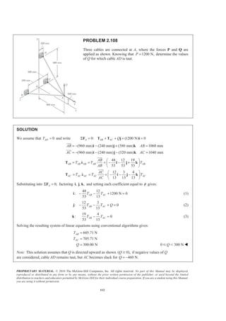
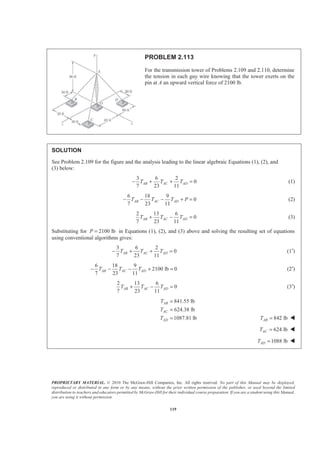
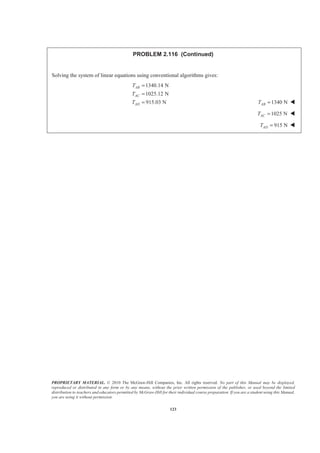
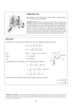
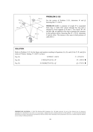
PROBLEM 2.123
A container of weight W is suspended from ring A, to
which cables AC and AE are attached. A force P is
applied to the end F of a third cable that passes over a
pulley at B and through ring A and that is attached to a
support at D. Knowing that 1000 N,W = determine the
magnitude of P. (Hint: The tension is the same in all
portions of cable FBAD.)
SOLUTION
The (vector) force in each cable can be written as the product of the (scalar) force and the unit vector along
the cable. That is, with
2 2 2
(0.78 m) (1.6 m) (0 m)
( 0.78 m) (1.6 m) (0)
1.78 m
[ (0.78 m) (1.6 m) (0 m) ]
1.78 m
( 0.4382 0.8989 0 )
AB AB AB
AB
AB AB
AB
AB
AB
T T
AB
T
T
= − + +
= − + +
=
= =
= − + +
= − + +
i j k
T Ȝ
i j k
T i j k
JJJG
JJJG
and
2 2 2
(0) (1.6 m) (1.2 m)
(0 m) (1.6 m) (1.2 m) 2 m
[(0) (1.6 m) (1.2 m) ]
2 m
(0.8 0.6 )
AC
AC AC AC
AC AC
AC
AC
TAC
T T
AC
T
= + +
= + + =
= = = + +
= +
i j k
T Ȝ i j k
T j k
JJJG
JJJG
and
2 2 2
(1.3 m) (1.6 m) (0.4 m)
(1.3 m) (1.6 m) (0.4 m) 2.1 m
[(1.3 m) (1.6 m) (0.4 m) ]
2.1 m
(0.6190 0.7619 0.1905 )
AD
AD AD AD
AD AD
AD
AD
TAD
T T
AD
T
= + +
= + + =
= = = + +
= + +
i j k
T Ȝ i j k
T i j k
JJJG
JJJG](https://image.slidesharecdn.com/mecanica-151208044028-lva1-app6892/85/Mecanica-130-320.jpg)
![PROPRIETARY MATERIAL. © 2010 The McGraw-Hill Companies, Inc. All rights reserved. No part of this Manual may be displayed,
reproduced or distributed in any form or by any means, without the prior written permission of the publisher, or used beyond the limited
distribution to teachers and educators permitted by McGraw-Hill for their individual course preparation. If you are a student using this Manual,
you are using it without permission.
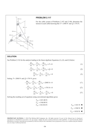
133
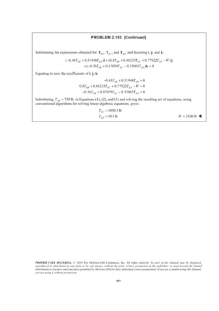
PROBLEM 2.123 (Continued)
Finally,
2 2 2
(0.4 m) (1.6 m) (0.86 m)
( 0.4 m) (1.6 m) ( 0.86 m) 1.86 m
[ (0.4 m) (1.6 m) (0.86 m) ]
1.86 m
( 0.2151 0.8602 0.4624 )
AE AE AE
AE
AE AE
AE
AE
AE
T T
AE
T
T
= − + −
= − + + − =
= =
= − + −
= − + −
i j k
T Ȝ
i j k
T i j k
JJJG
JJJG
With the weight of the container ,W= −W j at A we have:
0: 0AB AC AD WΣ = + + − =F T T T j
Equating the factors of i, j, and k to zero, we obtain the following linear algebraic equations:
0.4382 0.6190 0.2151 0AB AD AET T T− + − = (1)
0.8989 0.8 0.7619 0.8602 0AB AC AD AET T T T W+ + + − = (2)
0.6 0.1905 0.4624 0AC AD AET T T+ − = (3)
Knowing that 1000 NW = and that because of the pulley system at B ,AB ADT T P= = where P is the externally
applied (unknown) force, we can solve the system of linear Equations (1), (2) and (3) uniquely for P.
378 NP = W](https://image.slidesharecdn.com/mecanica-151208044028-lva1-app6892/85/Mecanica-131-320.jpg)

![PROPRIETARY MATERIAL. © 2010 The McGraw-Hill Companies, Inc. All rights reserved. No part of this Manual may be displayed,
reproduced or distributed in any form or by any means, without the prior written permission of the publisher, or used beyond the limited
distribution to teachers and educators permitted by McGraw-Hill for their individual course preparation. If you are a student using this Manual,
you are using it without permission.
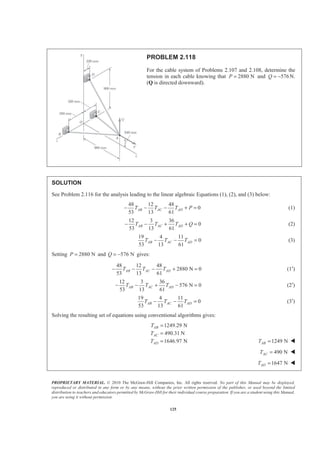
155
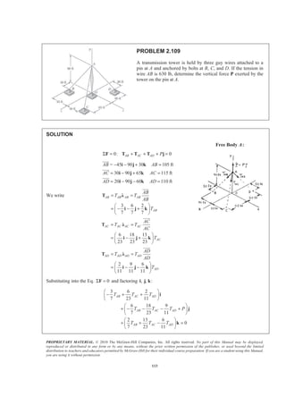
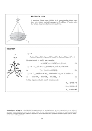
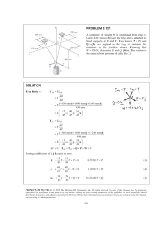
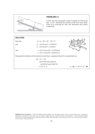
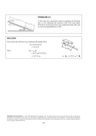
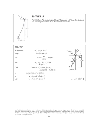
PROBLEM 3.3
A 300-N force is applied at A as shown. Determine (a) the moment
of the 300-N force about D, (b) the smallest force applied at B that
creates the same moment about D.
SOLUTION
(a) (300 N)cos 25
271.89 N
(300 N)sin 25
126.785 N
(271.89 N) (126.785 N)
x
y
F
F
= °
=
= °
=
= +F i j
(0.1m) (0.2 m)
[ (0.1m) (0.2 m) ] [(271.89 N) (126.785 N) ]
(12.6785 N m) (54.378 N m)
(41.700 N m)
D
D
DA= = − −
= ×
= − − × +
= − ⋅ + ⋅
= ⋅
r i j
M r F
M i j i j
k k
k
JJJG
41.7 N mD = ⋅M W
(b) The smallest force Q at B must be perpendicular to
DB
JJJG
at 45°
( )
41.700 N m (0.28284 m)
D Q DB
Q
=
⋅ =
M
JJJG
147.4 NQ = 45° W](https://image.slidesharecdn.com/mecanica-151208044028-lva1-app6892/85/Mecanica-153-320.jpg)
![PROPRIETARY MATERIAL. © 2010 The McGraw-Hill Companies, Inc. All rights reserved. No part of this Manual may be displayed,
reproduced or distributed in any form or by any means, without the prior written permission of the publisher, or used beyond the limited
distribution to teachers and educators permitted by McGraw-Hill for their individual course preparation. If you are a student using this Manual,
you are using it without permission.
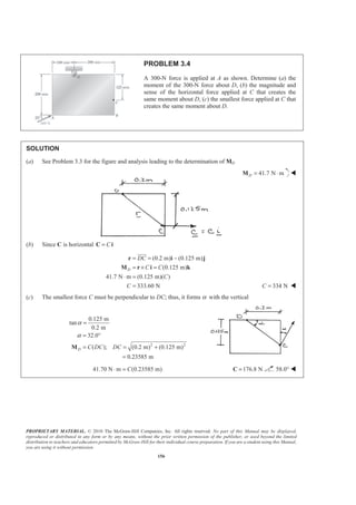
164
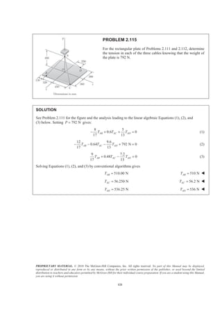
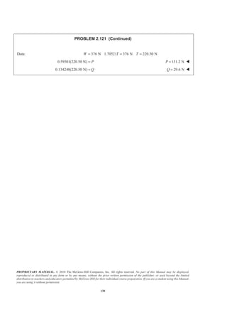
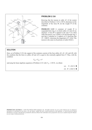
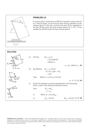
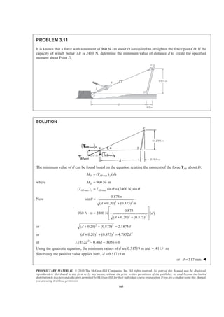
PROBLEM 3.12
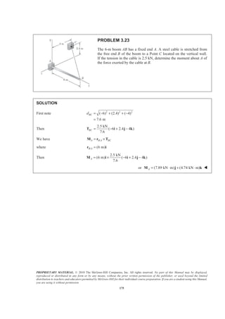
The tailgate of a car is supported by the hydraulic lift BC. If the
lift exerts a 125-lb force directed along its centerline on the ball
and socket at B, determine the moment of the force about A.
SOLUTION
First note 2 2
(12.0 in.) (2.33 in.)
12.2241in.
CBd = +
=
Then
12.0 in.
cos
12.2241in.
2.33 in.
sin
12.2241in.
θ
θ
=
=
and cos sin
125 lb
[(12.0 in.) (2.33 in.) ]
12.2241in.
CB CB CBF Fθ θ= −
= −
F i j
i j
Now /A B A CB= ×M r F
where / (15.3 in.) (12.0 in. 2.33 in.)
(15.3 in.) (14.33 in.)
B A = − +
= −
r i j
i j
Then
125 lb
[(15.3 in.) (14.33 in.) ] (12.0 2.33 )
12.2241in.
(1393.87 lb in.)
A = − × −
= ⋅
M i j i j
k
(116.156 lb ft)= ⋅ k or 116.2 lb ftA = ⋅M W](https://image.slidesharecdn.com/mecanica-151208044028-lva1-app6892/85/Mecanica-162-320.jpg)
![PROPRIETARY MATERIAL. © 2010 The McGraw-Hill Companies, Inc. All rights reserved. No part of this Manual may be displayed,
reproduced or distributed in any form or by any means, without the prior written permission of the publisher, or used beyond the limited
distribution to teachers and educators permitted by McGraw-Hill for their individual course preparation. If you are a student using this Manual,
you are using it without permission.
165
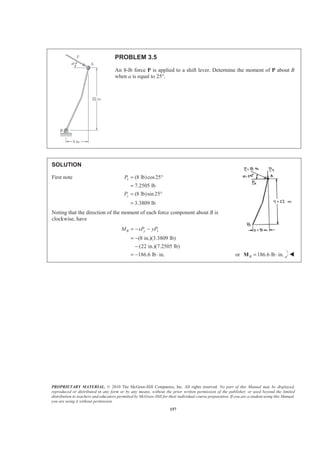
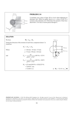
PROBLEM 3.13
The tailgate of a car is supported by the hydraulic lift BC. If the lift
exerts a 125-lb force directed along its centerline on the ball and
socket at B, determine the moment of the force about A.
SOLUTION
First note 2 2
(17.2 in.) (7.62 in.)
18.8123 in.
CBd = +
=
Then
17.2 in.
cos
18.8123 in.
7.62 in.
sin
18.8123 in.
θ
θ
=
=
and ( cos ) ( sin )
125 lb
[(17.2 in.) (7.62 in.) ]
18.8123 in.
CB CB CBF Fθ θ= −
= +
F i j
i j
Now /A B A CB= ×M r F
where / (20.5 in.) (4.38 in.)B A = −r i j
Then
125 lb
[(20.5 in.) (4.38 in.) ] (17.2 7.62 )
18.8123 in.
A = − × −M i j i j
(1538.53 lb in.)
(128.2 lb ft)
= ⋅
= ⋅
k
k or 128.2 lb ftA = ⋅M W](https://image.slidesharecdn.com/mecanica-151208044028-lva1-app6892/85/Mecanica-163-320.jpg)
![PROPRIETARY MATERIAL. © 2010 The McGraw-Hill Companies, Inc. All rights reserved. No part of this Manual may be displayed,
reproduced or distributed in any form or by any means, without the prior written permission of the publisher, or used beyond the limited
distribution to teachers and educators permitted by McGraw-Hill for their individual course preparation. If you are a student using this Manual,
you are using it without permission.
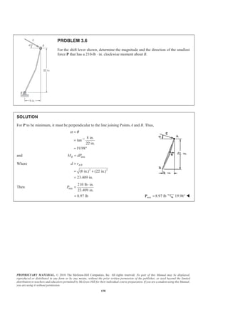
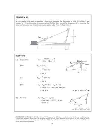
168
PROBLEM 3.16
A line passes through the Points (20 m, 16 m) and (−1 m, −4 m). Determine the perpendicular distance d from
the line to the origin O of the system of coordinates.
SOLUTION
2 2
[20 m ( 1 m)] [16 m ( 4 m)]
29 m
ABd = − − + − −
=
Assume that a force F, or magnitude F(N), acts at Point A and is
directed from A to B.
Then, ABF=F λ
Where
1
(21 20 )
29
B A
AB
ABd
−
=
= +
r r
i j
λ
By definition | |O A dF= × =M r F
Where (1 m) (4 m)A = − −r i j
Then [ ( 1 m) (4 m) ] [(21 m) (20 m) ]
29 m
[ (20) (84) ]
29
64
N m
29
O
F
F
F
= − − − × +
= − +
§ ·
= ⋅¨ ¸
© ¹
M i j i j
k k
k
Finally
64
( )
29
F d F
§ ·
=¨ ¸
© ¹
64
m
29
d = 2.21 md = W](https://image.slidesharecdn.com/mecanica-151208044028-lva1-app6892/85/Mecanica-166-320.jpg)
![PROPRIETARY MATERIAL. © 2010 The McGraw-Hill Companies, Inc. All rights reserved. No part of this Manual may be displayed,
reproduced or distributed in any form or by any means, without the prior written permission of the publisher, or used beyond the limited
distribution to teachers and educators permitted by McGraw-Hill for their individual course preparation. If you are a student using this Manual,
you are using it without permission.
169
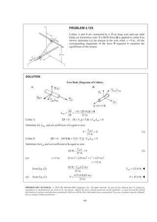
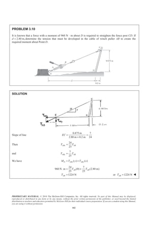
PROBLEM 3.17
The vectors P and Q are two adjacent sides of a parallelogram. Determine the area of the parallelogram when
(a) P = −7i + 3j − 3k and Q = 2i + 2j + 5k, (b) P = 6i − 5j − 2k and Q = −2i + 5j − k.
SOLUTION
(a) We have | |A = ×P Q
where 7 3 3= − + −P i j k
2 2 5= + +Q i j k
Then 7 3 3
2 2 5
[(15 6) ( 6 35) ( 14 6) ]
(21) (29) ( 20)
× = − −
= + + − + + − −
= + −
i j k
P Q
i j k
i j k
2 2 2
(20) (29) ( 20)A = + + − or 41.0A = W
(b) We have | |A = ×P Q
where 6 5 2= − −P i j k
2 5 in. 1= − + −Q i j k
Then 6 5 2
2 5 1
[(5 10) (4 6) (30 10) ]
(15) (10) (20)
× = − −
− −
= + + + + −
= + +
i j k
P Q
i j k
i j k
2 2 2
(15) (10) (20)A = + + or 26.9A = W](https://image.slidesharecdn.com/mecanica-151208044028-lva1-app6892/85/Mecanica-167-320.jpg)
![PROPRIETARY MATERIAL. © 2010 The McGraw-Hill Companies, Inc. All rights reserved. No part of this Manual may be displayed,
reproduced or distributed in any form or by any means, without the prior written permission of the publisher, or used beyond the limited
distribution to teachers and educators permitted by McGraw-Hill for their individual course preparation. If you are a student using this Manual,
you are using it without permission.
173
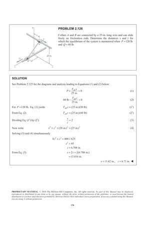
PROBLEM 3.21
A 200-N force is applied as shown to the bracket ABC. Determine
the moment of the force about A.
SOLUTION
We have /A C A C= ×M r F
where / (0.06 m) (0.075 m)
(200 N)cos 30 (200 N)sin 30
C A
C
= +
= − ° + °
r i j
F j k
Then 200 0.06 0.075 0
0 cos30 sin 30
200[(0.075sin 30 ) (0.06sin 30 ) (0.06cos 30 ) ]
A =
− ° °
= ° − ° − °
i j k
M
i j k
or (7.50 N m) (6.00 N m) (10.39 N m)A = ⋅ − ⋅ − ⋅M i j k W](https://image.slidesharecdn.com/mecanica-151208044028-lva1-app6892/85/Mecanica-171-320.jpg)
![PROPRIETARY MATERIAL. © 2010 The McGraw-Hill Companies, Inc. All rights reserved. No part of this Manual may be displayed,
reproduced or distributed in any form or by any means, without the prior written permission of the publisher, or used beyond the limited
distribution to teachers and educators permitted by McGraw-Hill for their individual course preparation. If you are a student using this Manual,
you are using it without permission.
174
PROBLEM 3.22
Before the trunk of a large tree is felled, cables AB and BC are
attached as shown. Knowing that the tensions in cables AB and BC
are 555 N and 660 N, respectively, determine the moment about O
of the resultant force exerted on the tree by the cables at B.
SOLUTION
We have /O B O B= ×M r F
where / (7 m)B O
B AB BC
=
= +
r j
F T T
2 2 2
2 2 2
(0.75 m) (7 m) (6 m)
(555 N)
(.75) (7) (6) m
(4.25 m) (7 m) (1m)
(660 N)
(4.25) (7) (1) m
[ (45.00 N) (420.0 N) (360.0 N) ]
[(340.0 N) (560.0 N) (80.00 N) ]
(295.0 N) (980.0 N) (4
AB BA AB
BC BC BC
B
T
T
=
− − +
=
+ +
=
− +
=
+ +
= − − +
+ − +
= − +
T Ȝ
i j k
T Ȝ
i j k
F i j k
i j k
i j 40.0 N)k
and 0 7 0 N m
295 980 440
O = ⋅
i j k
M
(3080 N m) (2070 N m)= ⋅ − ⋅i k or (3080 N m) (2070 N m)O = ⋅ − ⋅M i k W](https://image.slidesharecdn.com/mecanica-151208044028-lva1-app6892/85/Mecanica-172-320.jpg)
![PROPRIETARY MATERIAL. © 2010 The McGraw-Hill Companies, Inc. All rights reserved. No part of this Manual may be displayed,
reproduced or distributed in any form or by any means, without the prior written permission of the publisher, or used beyond the limited
distribution to teachers and educators permitted by McGraw-Hill for their individual course preparation. If you are a student using this Manual,
you are using it without permission.
185
PROBLEM 3.33
In Problem 3.26, determine the perpendicular distance from
Point C to portion AD of the line ABAD.
PROBLEM 3.26 A small boat hangs from two davits, one of
which is shown in the figure. The tension in line ABAD is
82 lb. Determine the moment about C of the resultant force
RA exerted on the davit at A.
SOLUTION
First compute the moment about C of the force DAF exerted by the line on D:
From Problem 3.26:
/
2 2
(48 lb) (62 lb) (24 lb)
(6 ft) [ (48 lb) (62 lb) (24 lb) ]
(144 lb ft) (372 lb ft)
(144) (372)
398.90 lb ft
DA AD
C D C DA
C
= −
= − + +
= ×
= + × − + +
= − ⋅ + ⋅
= +
= ⋅
F F
i j k
M r F
i i j k
j k
M
Then C DAd=M F
Since 82 lbDAF =
398.90 lb ft
82 lb
C
DA
M
d
F
=
⋅
= 4.86 ftd = W](https://image.slidesharecdn.com/mecanica-151208044028-lva1-app6892/85/Mecanica-183-320.jpg)
![PROPRIETARY MATERIAL. © 2010 The McGraw-Hill Companies, Inc. All rights reserved. No part of this Manual may be displayed,
reproduced or distributed in any form or by any means, without the prior written permission of the publisher, or used beyond the limited
distribution to teachers and educators permitted by McGraw-Hill for their individual course preparation. If you are a student using this Manual,
you are using it without permission.
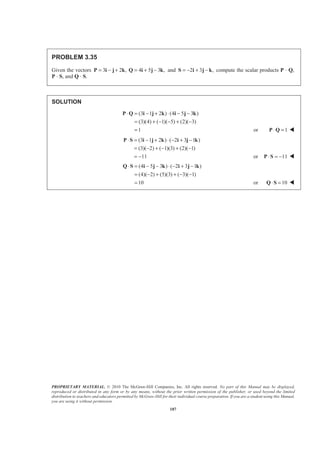
186
PROBLEM 3.34
Determine the value of a that minimizes the
perpendicular distance from Point C to a section
of pipeline that passes through Points A and B.
SOLUTION
Assuming a force F acts along AB,
/| | | | ( )C A C F d= × =M r F
Where d = perpendicular distance from C to line AB
2 2 2
/
(24 ft) (24 ft) (28)
(24) (24) (18) ft
(6) (6) (7)
11
(3 ft) (10 ft) ( 10 ft)
3 10 10
11
6 6 7
[(10 6 ) (81 6 ) 78 ]
11
AB
A C
C
F
F
F
a
F
a
F
a a
=
+ −
=
+ +
= + −
= − − −
= −
−
= + + − +
F Ȝ
i j k
i j k
r i j k
i j k
M
i j k
Since 2 2 2
/ /| | | | or | | ( )C A C A C dF= × × =M r F r F
2 2 2 21
(10 6 ) (81 6 ) (78)
121
a a d+ + − + =
Setting 2
( ) 0d
da
d = to find a to minimize d
1
[2(6)(10 6 ) 2( 6)(81 6 )] 0
121
a a+ + − − =
Solving 5.92 fta = or 5.92 fta = W](https://image.slidesharecdn.com/mecanica-151208044028-lva1-app6892/85/Mecanica-184-320.jpg)
![PROPRIETARY MATERIAL. © 2010 The McGraw-Hill Companies, Inc. All rights reserved. No part of this Manual may be displayed,
reproduced or distributed in any form or by any means, without the prior written permission of the publisher, or used beyond the limited
distribution to teachers and educators permitted by McGraw-Hill for their individual course preparation. If you are a student using this Manual,
you are using it without permission.
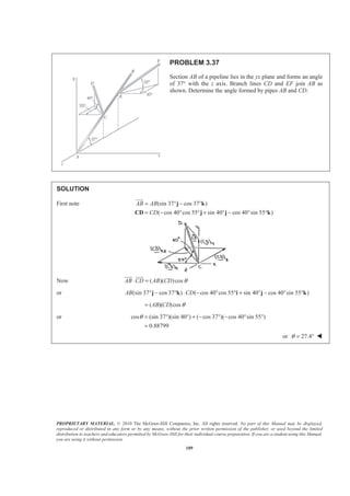
188
PROBLEM 3.36
Form the scalar products B C⋅ and ,′B C⋅ where ,B B′= and use the
results obtained to prove the identity
1 1
cos cos cos( ) cos( ).
2 2
a a aβ β β= + + −
SOLUTION
By definition cos( )BC α β= −B C⋅
where [(cos ) (sin ) ]
[(cos ) (sin ) ]
B
C
β β
α α
= +
= +
B i j
C i j
( cos )( cos ) ( sin )( sin ) cos( )B C B C BCβ α β α α β+ = −
or cos cos sin sin cos( )β α β α α β+ = − (1)
By definition cos( )BC α β′ = +B C⋅
where [(cos ) (sin ) ]β β′ = −B i j
( cos )( cos ) ( sin )( sin ) cos( )B C B C BCβ α β α α β+ − = +
or cos cos sin sin cos( )β α β α α β− = + (2)
Adding Equations (1) and (2),
2cos cos cos( ) cos( )β α α β α β= − + +
or
1 1
cos cos cos( ) cos( )
2 2
α β α β α β= + + − W](https://image.slidesharecdn.com/mecanica-151208044028-lva1-app6892/85/Mecanica-186-320.jpg)
![PROPRIETARY MATERIAL. © 2010 The McGraw-Hill Companies, Inc. All rights reserved. No part of this Manual may be displayed,
reproduced or distributed in any form or by any means, without the prior written permission of the publisher, or used beyond the limited
distribution to teachers and educators permitted by McGraw-Hill for their individual course preparation. If you are a student using this Manual,
you are using it without permission.
195
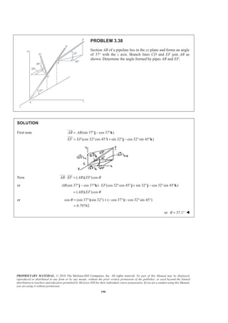
PROBLEM 3.43
Slider P can move along rod OA. An elastic cord PC is
attached to the slider and to the vertical member BC. Knowing
that the distance from O to P is 6 in. and that the tension in the
cord is 3 lb, determine (a) the angle between the elastic cord
and the rod OA, (b) the projection on OA of the force exerted
by cord PC at Point P.
SOLUTION
First note 2 2 2
(12) (12) ( 6) 18 in.OA = + + − =
Then
1
(12 12 6 )
18
1
(2 2 )
3
OA
OA
OA
= = + −
= + −
i j k
i j k
λ
Now
1
6 in. ( )
3
OP OP OA= Ÿ =
The coordinates of Point P are (4 in., 4 in., −2 in.)
so that (5 in.) (11 in.) (14 in.)PC = + +i j k
JJJG
and 2 2 2
(5) (11) (14) 342 in.PC = + + =
(a) We have ( )cosOAPC PC θ⋅ =
JJJG
λ
or
1
(5 11 14 ) (2 2 ) 342 cos
3
θ+ + ⋅ + − =i j k i j k
or
1
cos [(5)(2) (11)(2) (14)( 1)]
3 342
0.32444
θ = + + −
=
or 71.1θ = ° W
(b) We have ( )
( )
cos
(3 lb)(0.32444)
OAPC PC OA
PC PC OA
PC OA
PC
T
T
PC
T
PC
T θ
= ⋅
= ⋅
= ⋅
=
=
T λ
λ λ
λ
or ( ) 0.973 lbPC OAT = W](https://image.slidesharecdn.com/mecanica-151208044028-lva1-app6892/85/Mecanica-193-320.jpg)
![PROPRIETARY MATERIAL. © 2010 The McGraw-Hill Companies, Inc. All rights reserved. No part of this Manual may be displayed,
reproduced or distributed in any form or by any means, without the prior written permission of the publisher, or used beyond the limited
distribution to teachers and educators permitted by McGraw-Hill for their individual course preparation. If you are a student using this Manual,
you are using it without permission.
196
PROBLEM 3.44
Slider P can move along rod OA. An elastic cord PC is
attached to the slider and to the vertical member BC.
Determine the distance from O to P for which cord PC and
rod OA are perpendicular.
SOLUTION
First note 2 2 2
(12) (12) ( 6) 18 in.OA = + + − =
Then
1
(12 12 6 )
18
1
(2 2 )
3
OA
OA
OA
= = + −
= + −
i j k
i j k
λ
Let the coordinates of Point P be (x in., y in., z in.). Then
[(9 )in.] (15 )in.] [(12 )in.]PC x y z= − + − + −i j k
JJJG
Also, (2 2 )
3
OP
OP OA
d
OP d= = + −i j k
JJJG
λ
and ( in.) ( in.) ( in.)
2 2 1
3 3 3
OP OP OP
OP x y z
x d y d z d
= + +
= = =
i j k
JJJG
The requirement that OA and PC be perpendicular implies that
0OA PC⋅ =
JJJG
λ
or
1
(2 2 ) [(9 ) (15 ) (12 ) ] 0
3
x y z+ − ⋅ − + − + − =j j k i j k
or
2 2 1
(2) 9 (2) 15 ( 1) 12 0
3 3 3
OP OP OPd d d
ª º§ · § · § ·
− + − + − − − =« »¨ ¸ ¨ ¸ ¨ ¸
© ¹ © ¹ © ¹¬ ¼
or 12.00 in.OPd = W](https://image.slidesharecdn.com/mecanica-151208044028-lva1-app6892/85/Mecanica-194-320.jpg)


![PROPRIETARY MATERIAL. © 2010 The McGraw-Hill Companies, Inc. All rights reserved. No part of this Manual may be displayed,
reproduced or distributed in any form or by any means, without the prior written permission of the publisher, or used beyond the limited
distribution to teachers and educators permitted by McGraw-Hill for their individual course preparation. If you are a student using this Manual,
you are using it without permission.
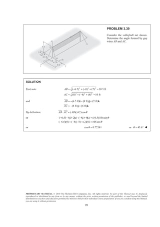
199
PROBLEM 3.47
The 0.61 1.00-m× lid ABCD of a storage bin is hinged
along side AB and is held open by looping cord DEC over a
frictionless hook at E. If the tension in the cord is 66 N,
determine the moment about each of the coordinate axes of
the force exerted by the cord at D.
SOLUTION
First note 2 2
(0.61) (0.11)
0.60 m
z = −
=
Then 2 2 2
(0.3) (0.6) ( 0.6)
0.9 m
DEd = + + −
=
and
66 N
(0.3 0.6 0.6 )
0.9
22[(1 N) (2 N) (2 N) ]
DE = + −
= + −
T i j k
i j k
Now /A D A DE= ×M r T
where / (0.11 m) (0.60 m)D A = +r j k
Then 22 0 0.11 0.60
1 2 2
22[( 0.22 1.20) 0.60 0.11 ]
(31.24 N m) (13.20 N m) (2.42 N m)
A =
−
= − − + −
= − ⋅ + ⋅ − ⋅
i j k
M
i j k
i j k
31.2 N m, 13.20 N m, 2.42 N mx y zM M M= − ⋅ = ⋅ = − ⋅ W](https://image.slidesharecdn.com/mecanica-151208044028-lva1-app6892/85/Mecanica-197-320.jpg)
![PROPRIETARY MATERIAL. © 2010 The McGraw-Hill Companies, Inc. All rights reserved. No part of this Manual may be displayed,
reproduced or distributed in any form or by any means, without the prior written permission of the publisher, or used beyond the limited
distribution to teachers and educators permitted by McGraw-Hill for their individual course preparation. If you are a student using this Manual,
you are using it without permission.
200
PROBLEM 3.48
The 0.61 1.00-m× lid ABCD of a storage bin is hinged
along side AB and is held open by looping cord DEC over a
frictionless hook at E. If the tension in the cord is 66 N,
determine the moment about each of the coordinate axes of
the force exerted by the cord at C.
SOLUTION
First note 2 2
(0.61) (0.11)
0.60 m
z = −
=
Then 2 2 2
( 0.7) (0.6) ( 0.6)
1.1 m
CEd = − + + −
=
and
66 N
( 0.7 0.6 0.6 )
1.1
6[ (7 N) (6 N) (6 N) ]
CE = − + −
= − + −
T i j k
i j k
Now /A E A CE= ×M r T
where / (0.3 m) (0.71 m)E A = +r i j
Then 6 0.3 0.71 0
7 6 6
6[ 4.26 1.8 (1.8 4.97) ]
(25.56 N m) (10.80 N m) (40.62 N m)
A =
− −
= − + + +
= − ⋅ + ⋅ + ⋅
i j k
M
i j k
i j k
25.6 N m, 10.80 N m, 40.6 N mx y zM M M= − ⋅ = ⋅ = ⋅ W](https://image.slidesharecdn.com/mecanica-151208044028-lva1-app6892/85/Mecanica-198-320.jpg)
![PROPRIETARY MATERIAL. © 2010 The McGraw-Hill Companies, Inc. All rights reserved. No part of this Manual may be displayed,
reproduced or distributed in any form or by any means, without the prior written permission of the publisher, or used beyond the limited
distribution to teachers and educators permitted by McGraw-Hill for their individual course preparation. If you are a student using this Manual,
you are using it without permission.
201
PROBLEM 3.49
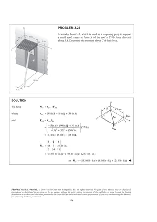
To lift a heavy crate, a man uses a block and tackle attached to the
bottom of an I-beam at hook B. Knowing that the moments about the y
and the z axes of the force exerted at B by portion AB of the rope are,
respectively, 120 N ⋅ m and −460 N ⋅ m, determine the distance a.
SOLUTION
First note (2.2 m) (3.2 m) ( m)BA a= − −i j k
JJJG
Now /D A D BA= ×M r T
where / (2.2 m) (1.6 m)
(2.2 3.2 ) (N)
A D
BA
BA
BA
T
a
d
= +
= − −
r i j
T i j k
Then 2.2 1.6 0
2.2 3.2
{ 1.6 2.2 [(2.2)( 3.2) (1.6)(2.2)] }
BA
D
BA
BA
BA
T
d
a
T
a a
d
=
− −
= − + + − −
i j k
M
i j k
Thus 2.2 (N m)
10.56 (N m)
BA
y
BA
BA
z
BA
T
M a
d
T
M
d
= ⋅
= − ⋅
Then forming the ratio
y
z
M
M
2.2 (N m)120 N m
460 N m 10.56 (N m)
BA
BA
BA
BA
T
d
T
d
⋅⋅
=
− ⋅ − ⋅
or 1.252 ma = W](https://image.slidesharecdn.com/mecanica-151208044028-lva1-app6892/85/Mecanica-199-320.jpg)
![PROPRIETARY MATERIAL. © 2010 The McGraw-Hill Companies, Inc. All rights reserved. No part of this Manual may be displayed,
reproduced or distributed in any form or by any means, without the prior written permission of the publisher, or used beyond the limited
distribution to teachers and educators permitted by McGraw-Hill for their individual course preparation. If you are a student using this Manual,
you are using it without permission.
205
PROBLEM 3.53
To loosen a frozen valve, a force F of magnitude 70 lb is
applied to the handle of the valve. Knowing that 25 ,θ = °
Mx 61lb ft,= − ⋅ and 43 lb ft,zM = − ⋅ determine φ and d.
SOLUTION
We have /:O A O OΣ × =M r F M
where / (4 in.) (11in.) ( )
(cos cos sin cos sin )
A O d
F θ φ θ θ φ
= − + −
= − +
r i j k
F i j k
For 70 lb, 25F θ= = °
(70 lb)[(0.90631cos ) 0.42262 (0.90631sin ) ]
(70 lb) 4 11 in.
0.90631cos 0.42262 0.90631sin
(70 lb)[(9.9694sin 0.42262 ) ( 0.90631 cos 3.6252sin )
(1.69048 9.9694cos ) ] in.
O d
d d
φ φ
φ φ
φ φ φ
φ
= − +
= − −
− −
= − + − +
+ −
F i j k
i j k
M
i j
k
and (70 lb)(9.9694sin 0.42262 )in. (61lb ft)(12 in./ft)xM dφ= − = − ⋅ (1)
(70 lb)( 0.90631 cos 3.6252sin ) in.yM d φ φ= − + (2)
(70 lb)(1.69048 9.9694cos ) in. 43 lb ft(12 in./ft)zM φ= − = − ⋅ (3)
From Equation (3) 1 634.33
cos 24.636
697.86
φ − § ·
= = °¨ ¸
© ¹
or 24.6φ = ° W
From Equation (1)
1022.90
34.577 in.
29.583
d
§ ·
= =¨ ¸
© ¹
or 34.6 in.d = W](https://image.slidesharecdn.com/mecanica-151208044028-lva1-app6892/85/Mecanica-203-320.jpg)

O F
F
θ φ θ θ φ
θ φ θ
θ φ θ φ
θ θ φ
= − − ⋅
−
= −
+ − +
+ − ⋅
i j k
M
i
j
k
and (11cos sin 27sin )(lb in.)xM F θ φ θ= − ⋅ (1)
( 27cos cos 4cos sin ) (lb in.)yM F θ φ θ φ= − + ⋅ (2)
(4sin 11cos cos ) (lb in.)zM F θ θ φ= − ⋅ (3)
Now, Equation (1)
1
cos sin 27sin
11
xM
F
θ φ θ
§ ·
= +¨ ¸
© ¹
(4)
and Equation (3)
1
cos cos 4sin
11
zM
F
θ φ θ
§ ·
= −¨ ¸
© ¹
(5)
Substituting Equations (4) and (5) into Equation (2),
1 1
27 4sin 4 27sin
11 11
xz
y
MM
M F
F F
θ θ
½ª ºª º § ·§ ·° °
= − − + +® ¾« »« » ¨ ¸¨ ¸
© ¹ © ¹° °¬ ¼ ¬ ¼¯ ¿
or
1
(27 4 )
11
y z xM M M= +](https://image.slidesharecdn.com/mecanica-151208044028-lva1-app6892/85/Mecanica-204-320.jpg)
![PROPRIETARY MATERIAL. © 2010 The McGraw-Hill Companies, Inc. All rights reserved. No part of this Manual may be displayed,
reproduced or distributed in any form or by any means, without the prior written permission of the publisher, or used beyond the limited
distribution to teachers and educators permitted by McGraw-Hill for their individual course preparation. If you are a student using this Manual,
you are using it without permission.
208
PROBLEM 3.55
The frame ACD is hinged at A and D and is supported by a
cable that passes through a ring at B and is attached to hooks
at G and H. Knowing that the tension in the cable is 450 N,
determine the moment about the diagonal AD of the force
exerted on the frame by portion BH of the cable.
SOLUTION
/( )AD AD B A BHM = ⋅ ×r Tλ
Where
/
1
(4 3 )
5
(0.5 m)
AD
B A
= −
=
i k
r i
λ
and 2 2 2
(0.375) (0.75) ( 0.75)
1.125 m
BHd = + + −
=
Then
450 N
(0.375 0.75 0.75 )
1.125
(150 N) (300 N) (300 N)
BH = + −
= + −
T i j k
i j k
Finally
4 0 3
1
0.5 0 0
5
150 300 300
1
[( 3)(0.5)(300)]
5
ADM
−
=
−
= −
or 90.0 N mADM = − ⋅ W](https://image.slidesharecdn.com/mecanica-151208044028-lva1-app6892/85/Mecanica-206-320.jpg)
![PROPRIETARY MATERIAL. © 2010 The McGraw-Hill Companies, Inc. All rights reserved. No part of this Manual may be displayed,
reproduced or distributed in any form or by any means, without the prior written permission of the publisher, or used beyond the limited
distribution to teachers and educators permitted by McGraw-Hill for their individual course preparation. If you are a student using this Manual,
you are using it without permission.
209
PROBLEM 3.56
In Problem 3.55, determine the moment about the diagonal AD
of the force exerted on the frame by portion BG of the cable.
SOLUTION
/( )AD AD B A BGM = ⋅ ×r Tλ
Where
/
1
(4 3 )
5
(0.5 m)
AD
B A
= −
=
i k
r j
λ
and 2 2 2
( 0.5) (0.925) ( 0.4)
1.125 m
BG = − + + −
=
Then
450 N
( 0.5 0.925 0.4 )
1.125
(200 N) (370 N) (160 N)
BG = − + −
= − + −
T i j k
i j k
JK
Finally
4 0 3
1
0.5 0 0
5
200 370 160
ADM
−
=
− −
1
[( 3)(0.5)(370)]
5
= − 111.0 N mADM = − ⋅ W](https://image.slidesharecdn.com/mecanica-151208044028-lva1-app6892/85/Mecanica-207-320.jpg)
![PROPRIETARY MATERIAL. © 2010 The McGraw-Hill Companies, Inc. All rights reserved. No part of this Manual may be displayed,
reproduced or distributed in any form or by any means, without the prior written permission of the publisher, or used beyond the limited
distribution to teachers and educators permitted by McGraw-Hill for their individual course preparation. If you are a student using this Manual,
you are using it without permission.
210
PROBLEM 3.57
The triangular plate ABC is supported by ball-and-socket joints
at B and D and is held in the position shown by cables AE and
CF. If the force exerted by cable AE at A is 55 N, determine the
moment of that force about the line joining Points D and B.
SOLUTION
First note 2 2 2
(0.9) ( 0.6) (0.2) 1.1 mAEd = + − + =
Then
55 N
(0.9 0.6 0.2 )
1.1
5[(9 N) (6 N) (2 N) ]
AE = − +
= − +
T i j k
i j k
Also 2 2 2
(1.2) ( 0.35) (0)
1.25 m
DB = + − +
=
Then
1
(1.2 0.35 )
1.25
1
(24 7 )
25
DB
DB
DB
=
= −
= −
i j
i j
JJJG
λ
Now /( )DB DB A D AEM = ⋅ ×r Tλ
where (0.1 m) (0.2 m)DA = − +T j k
Then
24 7 0
1
(5) 0 0.1 0.2
25
9 6 2
1
( 4.8 12.6 28.8)
5
DBM
−
= −
−
= − − +
or 2.28 N mDBM = ⋅ W](https://image.slidesharecdn.com/mecanica-151208044028-lva1-app6892/85/Mecanica-208-320.jpg)
![PROPRIETARY MATERIAL. © 2010 The McGraw-Hill Companies, Inc. All rights reserved. No part of this Manual may be displayed,
reproduced or distributed in any form or by any means, without the prior written permission of the publisher, or used beyond the limited
distribution to teachers and educators permitted by McGraw-Hill for their individual course preparation. If you are a student using this Manual,
you are using it without permission.
211
PROBLEM 3.58
The triangular plate ABC is supported by ball-and-socket joints
at B and D and is held in the position shown by cables AE and
CF. If the force exerted by cable CF at C is 33 N, determine the
moment of that force about the line joining Points D and B.
SOLUTION
First note 2 2 2
(0.6) ( 0.9) ( 0.2) 1.1 mCFd = + − + − =
Then
33 N
(0.6 0.9 0.2 )
1.1
3[(6 N) (9 N) (2 N) ]
CF = − +
= − −
T i j k
i j k
Also 2 2 2
(1.2) ( 0.35) (0)
1.25 m
DB = + − +
=
Then
1
(1.2 0.35 )
1.25
1
(24 7 )
25
DB
DB
DB
=
= −
= −
i j
i j
JJJG
λ
Now /( )DB DB C D CFM = ⋅ ×r Tλ
where / (0.2 m) (0.4 m)C D = −r j k
Then
24 7 0
1
(3) 0 0.2 0.4
25
6 9 2
3
( 9.6 16.8 86.4)
25
DBM
−
= −
− −
= − + −
or 9.50 N mDBM = − ⋅ W](https://image.slidesharecdn.com/mecanica-151208044028-lva1-app6892/85/Mecanica-209-320.jpg)
![PROPRIETARY MATERIAL. © 2010 The McGraw-Hill Companies, Inc. All rights reserved. No part of this Manual may be displayed,
reproduced or distributed in any form or by any means, without the prior written permission of the publisher, or used beyond the limited
distribution to teachers and educators permitted by McGraw-Hill for their individual course preparation. If you are a student using this Manual,
you are using it without permission.
214
PROBLEM 3.61
A sign erected on uneven ground is
guyed by cables EF and EG. If the
force exerted by cable EF at E is 46 lb,
determine the moment of that force
about the line joining Points A and D.
SOLUTION
First note that 2 2
(48) (36) 60 in.BC = + = and that 45 3
60 4
.BE
BC
= = The coordinates of Point E are
then ( )3 3
4 4
48, 96, 36 or (36 in., 96 in., 27 in.).× × Then
2 2 2
( 15) ( 110) (30)
115 in.
EFd = − + − +
=
Then
46 lb
( 15 110 30 )
115
2[ (3 lb) (22 lb) (6 lb) ]
EF = − − +
= − − +
T i j k
i j k
Also 2 2 2
(48) ( 12) (36)
12 26 in.
AD = + − +
=
Then
1
(48 12 36 )
12 26
1
(4 3 )
26
AD
AD
AD
=
= − +
= − +
i j k
i j k
JJJG
λ
Now /( )AD AD E A EFM = ⋅ ×r Tλ](https://image.slidesharecdn.com/mecanica-151208044028-lva1-app6892/85/Mecanica-212-320.jpg)
![PROPRIETARY MATERIAL. © 2010 The McGraw-Hill Companies, Inc. All rights reserved. No part of this Manual may be displayed,
reproduced or distributed in any form or by any means, without the prior written permission of the publisher, or used beyond the limited
distribution to teachers and educators permitted by McGraw-Hill for their individual course preparation. If you are a student using this Manual,
you are using it without permission.
216
PROBLEM 3.62
A sign erected on uneven ground is
guyed by cables EF and EG. If the
force exerted by cable EG at E is 54 lb,
determine the moment of that force
about the line joining Points A and D.
SOLUTION
First note that 2 2
(48) (36) 60 in.BC = + = and that 45 3
60 4
.BE
BC
= = The coordinates of Point E are
then ( )3 3
4 4
48, 96, 36 or (36 in., 96 in., 27 in.).× × Then
2 2 2
(11) ( 88) ( 44)
99 in.
EGd = + − + −
=
Then
54 lb
(11 88 44 )
99
6[(1 lb) (8 lb) (4 lb) ]
EG = − −
= − −
T i j k
i j k
Also 2 2 2
(48) ( 12) (36)
12 26 in.
AD = + − +
=
Then
1
(48 12 36 )
12 26
1
(4 3 )
26
AD
AD
AD
=
= − +
= − +
i j k
i j k
JJJG
λ
Now /( )AD AD E A EGM = ⋅ ×r Tλ](https://image.slidesharecdn.com/mecanica-151208044028-lva1-app6892/85/Mecanica-214-320.jpg)
![PROPRIETARY MATERIAL. © 2010 The McGraw-Hill Companies, Inc. All rights reserved. No part of this Manual may be displayed,
reproduced or distributed in any form or by any means, without the prior written permission of the publisher, or used beyond the limited
distribution to teachers and educators permitted by McGraw-Hill for their individual course preparation. If you are a student using this Manual,
you are using it without permission.
219
PROBLEM 3.64
In Problem 3.55, determine the perpendicular distance between
portion BH of the cable and the diagonal AD.
PROBLEM 3.55 The frame ACD is hinged at A and D and is
supported by a cable that passes through a ring at B and is
attached to hooks at G and H. Knowing that the tension in the
cable is 450 N, determine the moment about the diagonal AD
of the force exerted on the frame by portion BH of the cable.
SOLUTION
From the solution to Problem 3.55: 450 N
(150 N) (300 N) (300 N)
BH
BH
T =
= + −T i j k
| | 90.0 N mADM = ⋅
1
(4 3 )
5
AD = −i kλ
Based on the discussion of Section 3.11, it follows that only the perpendicular component of TBH will
contribute to the moment of TBH about line .AD
JJJG
Now parallel( )
1
(150 300 300 ) (4 3 )
5
1
[(150)(4) ( 300)( 3)]
5
300 N
BH BH ADT = ⋅
= + − ⋅ −
= + − −
=
T
i j k i k
λ
Also parallel perpendicular( ) ( )BH BH BH= +T T T
so that 2 2
perpendicular( ) (450) (300) 335.41 NBHT = − =
Since ADλ and perpendicular( )BHT are perpendicular, it follows that
perpendicular( )AD BHM d T=
or 90.0 N m (335.41 N)d⋅ =
0.26833 md = 0.268 md = W](https://image.slidesharecdn.com/mecanica-151208044028-lva1-app6892/85/Mecanica-217-320.jpg)
![PROPRIETARY MATERIAL. © 2010 The McGraw-Hill Companies, Inc. All rights reserved. No part of this Manual may be displayed,
reproduced or distributed in any form or by any means, without the prior written permission of the publisher, or used beyond the limited
distribution to teachers and educators permitted by McGraw-Hill for their individual course preparation. If you are a student using this Manual,
you are using it without permission.
220
PROBLEM 3.65
In Problem 3.56, determine the perpendicular distance between
portion BG of the cable and the diagonal AD.
PROBLEM 3.56 In Problem 3.55, determine the moment
about the diagonal AD of the force exerted on the frame by
portion BG of the cable.
SOLUTION
From the solution to Problem 3.56: 450 N
(200 N) (370 N) (160 N)
BG
BG
=
= − + −T i j k
Τ
| | 111 N mADM = ⋅
1
(4 3 )
5
AD = −i kλ
Based on the discussion of Section 3.11, it follows that only the perpendicular component of TBG will
contribute to the moment of TBG about line .AD
JJJK
Now parallel( )
1
( 200 370 160 ) (4 3 )
5
1
[( 200)(4) ( 160)( 3)]
5
64 N
BG BG ADT = ⋅
= − + − ⋅ −
= − + − −
= −
T
i j k i k
λ
Also parallel perpendicular( ) ( )BG BG BG= +T T T
so that 2 2
perpendicular( ) (450) ( 64) 445.43 NBG = − − =T
Since ADλ and perpendicular( )BGT are perpendicular, it follows that
perpendicular( )AD BGM d T=
or 111 N m (445.43 N)d⋅ =
0.24920 md = 0.249 md = W](https://image.slidesharecdn.com/mecanica-151208044028-lva1-app6892/85/Mecanica-218-320.jpg)
![PROPRIETARY MATERIAL. © 2010 The McGraw-Hill Companies, Inc. All rights reserved. No part of this Manual may be displayed,
reproduced or distributed in any form or by any means, without the prior written permission of the publisher, or used beyond the limited
distribution to teachers and educators permitted by McGraw-Hill for their individual course preparation. If you are a student using this Manual,
you are using it without permission.
221
PROBLEM 3.66
In Problem 3.57, determine the perpendicular distance between
cable AE and the line joining Points D and B.
PROBLEM 3.57 The triangular plate ABC is supported by
ball-and-socket joints at B and D and is held in the position
shown by cables AE and CF. If the force exerted by cable AE
at A is 55 N, determine the moment of that force about the line
joining Points D and B.
SOLUTION
From the solution to Problem 3.57 55 N
5[(9 N) (6 N) (2 N) ]
AE
AE
=
= − +T i j k
Τ
| | 2.28 N mDBM = ⋅
1
(24 7 )
25
DB = −i jλ
Based on the discussion of Section 3.11, it follows that only the perpendicular component of TAE will
contribute to the moment of TAE about line .DB
JJJG
Now parallel( )
1
5(9 6 2 ) (24 7 )
25
1
[(9)(24) ( 6)( 7)]
5
51.6 N
AE AE DBT = ⋅
= − + ⋅ −
= + − −
=
T
i j k i j
λ
Also parallel perpendicular( ) ( )AE AE AE= +T T T
so that 2 2
perpendicular( ) (55) (51.6) 19.0379 NAE = + =T
Since DBλ and perpendicular( )AET are perpendicular, it follows that
perpendicular( )DB AEM d T=
or 2.28 N m (19.0379 N)d⋅ =
0.119761d = 0.1198 md = W](https://image.slidesharecdn.com/mecanica-151208044028-lva1-app6892/85/Mecanica-219-320.jpg)
![PROPRIETARY MATERIAL. © 2010 The McGraw-Hill Companies, Inc. All rights reserved. No part of this Manual may be displayed,
reproduced or distributed in any form or by any means, without the prior written permission of the publisher, or used beyond the limited
distribution to teachers and educators permitted by McGraw-Hill for their individual course preparation. If you are a student using this Manual,
you are using it without permission.
222
PROBLEM 3.67
In Problem 3.58, determine the perpendicular distance
between cable CF and the line joining Points D and B.
PROBLEM 3.58 The triangular plate ABC is supported by
ball-and-socket joints at B and D and is held in the position
shown by cables AE and CF. If the force exerted by cable CF at
C is 33 N, determine the moment of that force about the line
joining Points D and B.
SOLUTION
From the solution to Problem 3.58 33 N
3[(6 N) (9 N) (2 N) ]
CF
CF
=
= − −T i j k
Τ
| | 9.50 N mDBM = ⋅
1
(24 7 )
25
DB = −i jλ
Based on the discussion of Section 3.11, it follows that only the perpendicular component of TCF will
contribute to the moment of TCF about line .DB
JJJG
Now parallel( )
1
3(6 9 2 ) (24 7 )
25
3
[(6)(24) ( 9)( 7)]
25
24.84 N
CF CF DB= ⋅
= − − ⋅ −
= + − −
=
T T
i j k i j
λ
Also parallel perpendicular( ) ( )CF CF CF= +T T T
so that 2 2
perpendicular( ) (33) (24.84)
21.725 N
CF = −
=
T
Since DBλ and perpendicular( )CFT are perpendicular, it follows that
perpendicular| | ( )DB CFM d T=
or 9.50 N m 21.725 Nd⋅ = ×
or 0.437 md = W](https://image.slidesharecdn.com/mecanica-151208044028-lva1-app6892/85/Mecanica-220-320.jpg)
![PROPRIETARY MATERIAL. © 2010 The McGraw-Hill Companies, Inc. All rights reserved. No part of this Manual may be displayed,
reproduced or distributed in any form or by any means, without the prior written permission of the publisher, or used beyond the limited
distribution to teachers and educators permitted by McGraw-Hill for their individual course preparation. If you are a student using this Manual,
you are using it without permission.
223
PROBLEM 3.68
In Problem 3.61, determine the perpendicular
distance between cable EF and the line joining
Points A and D.
PROBLEM 3.61 A sign erected on uneven
ground is guyed by cables EF and EG. If the
force exerted by cable EF at E is 46 lb,
determine the moment of that force about
the line joining Points A and D.
SOLUTION
From the solution to Problem 3.61 46 lb
2[ (3 lb) (22 lb) (6 lb) ]
EF
EF
T =
= − − +T i j k
| | 1359 lb in.ADM = ⋅
1
(4 3 )
26
AD = − +i j kλ
Based on the discussion of Section 3.11, it follows that only the perpendicular component of TEF will
contribute to the moment of TEF about line .AD
JJJG
Now parallel( )
1
2( 3 22 6 ) (4 3 )
26
2
[( 3)(4) ( 22)( 1) (6)(3)]
26
10.9825 lb
EF EF ADT = ⋅
= − − + ⋅ − +
= − + − − +
=
T
i j k i j k
λ
Also parallel perpendicular( ) ( )EF EF EF= +T T T
so that 2 2
perpendicular( ) (46) (10.9825) 44.670 lbEF = − =T
Since ADλ and perpendicular( )EFT are perpendicular, it follows that
perpendicular( )AD EFM d T=
or 1359 lb in. 44.670 lbd⋅ = × or 30.4 in.d = W](https://image.slidesharecdn.com/mecanica-151208044028-lva1-app6892/85/Mecanica-221-320.jpg)
![PROPRIETARY MATERIAL. © 2010 The McGraw-Hill Companies, Inc. All rights reserved. No part of this Manual may be displayed,
reproduced or distributed in any form or by any means, without the prior written permission of the publisher, or used beyond the limited
distribution to teachers and educators permitted by McGraw-Hill for their individual course preparation. If you are a student using this Manual,
you are using it without permission.
224
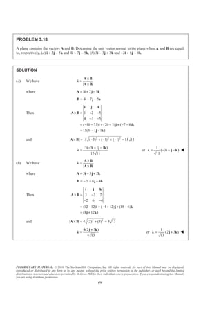
PROBLEM 3.69
In Problem 3.62, determine the perpendicular
distance between cable EG and the line joining
Points A and D.
PROBLEM 3.62 A sign erected on uneven
ground is guyed by cables EF and EG. If the
force exerted by cable EG at E is 54 lb,
determine the moment of that force about the
line joining Points A and D.
SOLUTION
From the solution to Problem 3.62 54 lb
6[(1 lb) (8 lb) (4 lb) ]
EG
EG
T =
= − −T i j k
| | 2350 lb in.ADM = ⋅
1
(4 3 )
26
AD = − +i j kλ
Based on the discussion of Section 3.11, it follows that only the perpendicular component of TEG will
contribute to the moment of TEG about line .AD
JJJG
Now parallel( )
1
6( 8 4 ) (4 3 )
26
6
[(1)(4) ( 8)( 1) ( 4)(3)] 0
26
EG EG ADT = ⋅
= − − ⋅ − +
= + − − + − =
T
i j k i j k
λ
Thus, perpendicular( ) 54 lbEG EG= =T T
Since ADλ and perpendicular( )EGT are perpendicular, it follows that
perpendicular| | ( )AD EGM d T=
or 2350 lb in. 54 lbd⋅ = ×
or 43.5 in.d = W](https://image.slidesharecdn.com/mecanica-151208044028-lva1-app6892/85/Mecanica-222-320.jpg)

Fd= −
= ° − ° −
M k
k
(12.3893 N m)= − ⋅ k or 12.39 N m= ⋅M W
(c) We have / /: ( )A A B A B C A CΣ Σ × = × + × =M r F r F r F M
(0.520 m)(60 N) cos55 sin55 0
cos20 sin 20 0
(0.800 m)(60 N) cos55 sin55 0
cos20 sin 20 0
(17.8956 N m 30.285 N m)
(12.3892 N m)
M = ° °
− ° − °
+ ° °
° °
= ⋅ − ⋅
= − ⋅
i j k
i j k
k
k or 12.39 N m= ⋅M W](https://image.slidesharecdn.com/mecanica-151208044028-lva1-app6892/85/Mecanica-223-320.jpg)
 [(8 )in.](25 lb)
AD AD BC BCM d F d F
d d
= +
⋅ = + + + 1.250 in.d = W](https://image.slidesharecdn.com/mecanica-151208044028-lva1-app6892/85/Mecanica-227-320.jpg)
![PROPRIETARY MATERIAL. © 2010 The McGraw-Hill Companies, Inc. All rights reserved. No part of this Manual may be displayed,
reproduced or distributed in any form or by any means, without the prior written permission of the publisher, or used beyond the limited
distribution to teachers and educators permitted by McGraw-Hill for their individual course preparation. If you are a student using this Manual,
you are using it without permission.
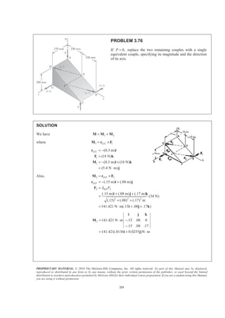
232
PROBLEM 3.76 (Continued)
and [(5.4 N m) ] [141.421(.0136 .0255 ) N m]
(1.92333 N m) (9.0062 N m)
= ⋅ + + ⋅
= ⋅ + ⋅
M j i j
i j
2 2
2 2
| | ( ) ( )
(1.92333) (9.0062)
9.2093 N m
x yM M= +
= +
= ⋅
M
or 9.21 N mM = ⋅ W
(1.92333 N m) (9.0062 N m)
| | 9.2093 N m
0.20885 0.97795
cos 0.20885
77.945
x
x
λ
θ
θ
⋅ + ⋅
= =
⋅
= +
=
= °
M i j
M
or 77.9xθ = ° W
cos 0.97795
12.054
y
y
θ
θ
=
= ° or 12.05yθ = ° W
cos 0.0
90
z
z
θ
θ
=
= ° or z 90.0θ = ° W](https://image.slidesharecdn.com/mecanica-151208044028-lva1-app6892/85/Mecanica-230-320.jpg)
![PROPRIETARY MATERIAL. © 2010 The McGraw-Hill Companies, Inc. All rights reserved. No part of this Manual may be displayed,
reproduced or distributed in any form or by any means, without the prior written permission of the publisher, or used beyond the limited
distribution to teachers and educators permitted by McGraw-Hill for their individual course preparation. If you are a student using this Manual,
you are using it without permission.
233
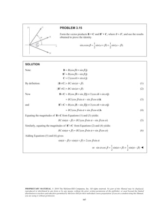
PROBLEM 3.77
If 0,P = replace the two remaining couples with a single
equivalent couple, specifying its magnitude and the direction
of its axis.
SOLUTION
1 2 1 2
1
/ 2 /
2 2 2
2
2
; 16 lb, 40 lb
(30 in.) [ (16 lb) ] (480 lb in.)
; (15 in.) (5 in.)
(0) (5) (10) 5 5 in.
40 lb
(5 10 )
5 5
8 5[(1 lb) (2 lb) ]
8 5 15 5 0
0 1 2
8 5[(10 lb in.)
C
E B E B
DE
F F
d
F
= + = =
= × = × − = − ⋅
= × = −
= + + =
= −
= −
= −
−
= ⋅
1
2
M M M
M r F i j k
M r F r i j
j k
j k
i j k
M
i (30 lb in.) (15 lb in.) ]
(480 lb in.) 8 5[(10 lb in.) (30 lb in.) (15 lb in.) ]
(178.885 lb in.) (536.66 lb in.) (211.67 lb in.)
+ ⋅ + ⋅
= − ⋅ + ⋅ + ⋅ + ⋅
= ⋅ + ⋅ − ⋅
j k
M k i j k
i j k
2 2 2
(178.885) (536.66) ( 211.67)
603.99 lb in
M = + + −
= ⋅ 604 lb in.M = ⋅ W
axis
z
0.29617 0.88852 0.35045
cos 0.29617
cos 0.88852
cos 0.35045
x
y
M
θ
θ
θ
= = + −
=
=
= −
M
i j kλ
z72.8 27.3 110.5x yθ θ θ= ° = ° = ° W](https://image.slidesharecdn.com/mecanica-151208044028-lva1-app6892/85/Mecanica-231-320.jpg)
![PROPRIETARY MATERIAL. © 2010 The McGraw-Hill Companies, Inc. All rights reserved. No part of this Manual may be displayed,
reproduced or distributed in any form or by any means, without the prior written permission of the publisher, or used beyond the limited
distribution to teachers and educators permitted by McGraw-Hill for their individual course preparation. If you are a student using this Manual,
you are using it without permission.
234
PROBLEM 3.78
If 20 lb,P = replace the three couples with a single
equivalent couple, specifying its magnitude and the
direction of its axis.
SOLUTION
From the solution to Problem. 3.77
16 lb force: 1 (480 lb in.)M = − ⋅ k
40 lb force: 2 8 5[(10 lb in.) (30 lb in.) (15 lb in.) ]M = ⋅ + ⋅ + ⋅i j k
P 20 lb= 3
(30 in.) (20 lb)
(600 lb in.)
CM P= ×
= ×
= ⋅
r
i k
j
1 2 3
2 2 2
(480) 8 5 (10 30 15 ) 600
(178.885 lb in) (1136.66 lb in.) (211.67 lb in.)
(178.885) (113.66) (211.67)
1169.96 lb in
M
= + +
= − + + + +
= ⋅ + ⋅ − ⋅
= + +
= ⋅
M M M M
k i j k j
i j k
1170 lb in.M = ⋅ W
axis 0.152898 0.97154 0.180921
cos 0.152898
cos 0.97154
cos 0.180921
x
y
z
M
θ
θ
θ
= = + −
=
=
= −
M
i j kλ
81.2 13.70 100.4x y zθ θ θ= ° = ° = ° W](https://image.slidesharecdn.com/mecanica-151208044028-lva1-app6892/85/Mecanica-232-320.jpg)
![PROPRIETARY MATERIAL. © 2010 The McGraw-Hill Companies, Inc. All rights reserved. No part of this Manual may be displayed,
reproduced or distributed in any form or by any means, without the prior written permission of the publisher, or used beyond the limited
distribution to teachers and educators permitted by McGraw-Hill for their individual course preparation. If you are a student using this Manual,
you are using it without permission.
235
PROBLEM 3.79
If 20 N,P = replace the three couples with a single
equivalent couple, specifying its magnitude and the
direction of its axis.
SOLUTION
We have 1 2 3= + +M M M M
where
1 / 1
2 / 2
0.3 0 0 N m (5.4 N m)
0 0 18
.15 .08 0 141.421 N m
.15 .08 .17
141.421(.0136 .0255 )N m
G C
D F
= × = − ⋅ = ⋅
= × = − ⋅
−
= + ⋅
i j k
M r F j
i j k
M r F
i j
(See Solution to Problem 3.76.)
3 / 3 0.3 0 0.17 N m
0 20 0
(3.4 N m) (6 N m)
[(1.92333 3.4) (5.4 3.6062) (6) ]N m
(1.47667 N m) (9.0062 N m) (6 N m)
C A= × = ⋅
= − ⋅ + ⋅
= − + + + ⋅
= − ⋅ + ⋅ + ⋅
i j k
M r F
i k
M i j k
i j
2 2 2
| | x y zM M M= + +M
2
(1.47667) (9.0062) (6)
10.9221 N m
= + +
= ⋅ or 10.92 N mM = ⋅ W](https://image.slidesharecdn.com/mecanica-151208044028-lva1-app6892/85/Mecanica-233-320.jpg)
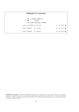
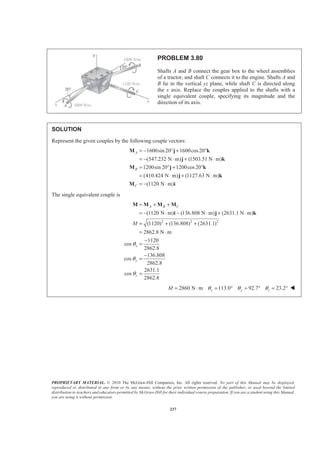
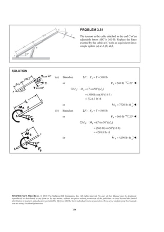
 (6 ft)
20.0 lb
B
B
P
P
° =
= or 20.0 lbB =P W](https://image.slidesharecdn.com/mecanica-151208044028-lva1-app6892/85/Mecanica-237-320.jpg)

 ( cos30 )(10.7 m)C AM FΣ ° = °
388.79 NAF =
or 389 NA =F 60° W
Based on
: [(1040 N)cos30 ](6.7 m) ( cos30 )(10.7 m)A CM FΣ − ° = °
651.21 NCF =
or 651 NC =F 60° W](https://image.slidesharecdn.com/mecanica-151208044028-lva1-app6892/85/Mecanica-240-320.jpg)
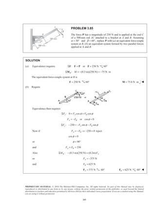
![PROPRIETARY MATERIAL. © 2010 The McGraw-Hill Companies, Inc. All rights reserved. No part of this Manual may be displayed,
reproduced or distributed in any form or by any means, without the prior written permission of the publisher, or used beyond the limited
distribution to teachers and educators permitted by McGraw-Hill for their individual course preparation. If you are a student using this Manual,
you are using it without permission.
244
PROBLEM 3.86
Solve Problem 3.85, assuming 25°.α β= =
SOLUTION
(a) Equivalence requires
: or 250 NB BΣ = =F F P F 25.0°
: (0.3 m)[(250 N)sin50 ] 57.453 N mB BMΣ = − ° = − ⋅M
The equivalent force-couple system at B is
250 NB =F 25.0° 57.5 N mB = ⋅M W
(b) Require
Equivalence requires
(0.3 m)[(250 N)sin50 ]
[(0.2 m)sin50 ]
375 N
B AEM d Q
Q
Q
= °
= °
=
Adding the forces at B: 375 NA =F 25.0° 625 NB =F 25.0° W](https://image.slidesharecdn.com/mecanica-151208044028-lva1-app6892/85/Mecanica-242-320.jpg)
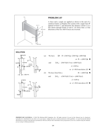
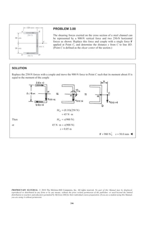
![PROPRIETARY MATERIAL. © 2010 The McGraw-Hill Companies, Inc. All rights reserved. No part of this Manual may be displayed,
reproduced or distributed in any form or by any means, without the prior written permission of the publisher, or used beyond the limited
distribution to teachers and educators permitted by McGraw-Hill for their individual course preparation. If you are a student using this Manual,
you are using it without permission.
247
PROBLEM 3.89
While tapping a hole, a machinist applies the horizontal forces
shown to the handle of the tap wrench. Show that these forces
are equivalent to a single force, and specify, if possible, the
point of application of the single force on the handle.
SOLUTION
Since the forces at A and B are parallel, the force at B can be replaced with the sum of two forces with one of
the forces equal in magnitude to the force at A except with an opposite sense, resulting in a force-couple.
Have 2.9 lb 2.65 lb 0.25 lb,BF = − = where the 2.65 lb force be part of the couple. Combining the two
parallel forces,
couple (2.65 lb)[(3.2 in. 2.8 in.)cos25 ]
14.4103 lb in.
M = + °
= ⋅
and couple 14.4103 lb in.= ⋅M
A single equivalent force will be located in the negative z-direction
Based on : 14.4103 lb in. [(.25 lb)cos 25 ]( )BM aΣ − ⋅ = °
63.600 in.a =
F′ (.25 lb)(cos 25 sin 25 )= ° + °i k
F′ (0.227 lb) (0.1057 lb)= +i k and is applied on an extension of handle BD at a
distance of 63.6 in. to the right of B W](https://image.slidesharecdn.com/mecanica-151208044028-lva1-app6892/85/Mecanica-245-320.jpg)
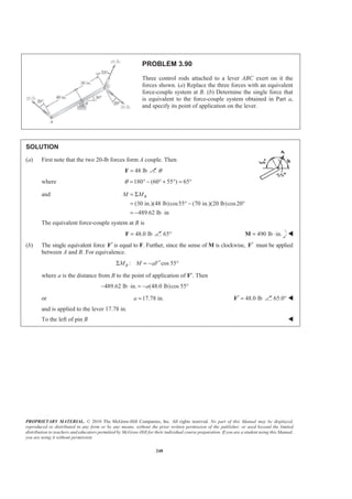
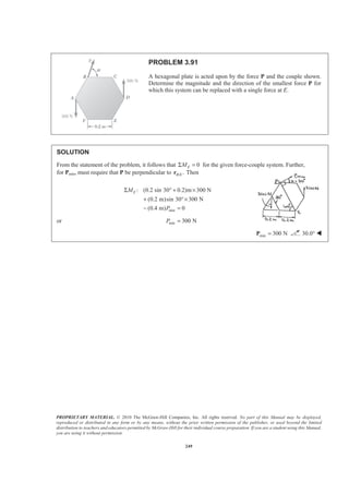
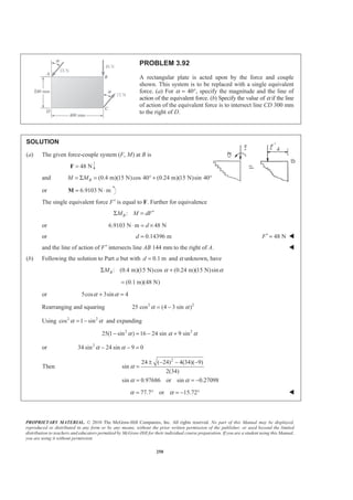
![PROPRIETARY MATERIAL. © 2010 The McGraw-Hill Companies, Inc. All rights reserved. No part of this Manual may be displayed,
reproduced or distributed in any form or by any means, without the prior written permission of the publisher, or used beyond the limited
distribution to teachers and educators permitted by McGraw-Hill for their individual course preparation. If you are a student using this Manual,
you are using it without permission.
251
PROBLEM 3.93
An eccentric, compressive 1220-N force P is applied to the end
of a cantilever beam. Replace P with an equivalent force-couple
system at G.
SOLUTION
We have
: (1220 N)Σ − =F i F
(1220 N)= −F i W
Also, we have
/:G A GΣ × =M r P M
1220 0 .1 .06 N m
1 0 0
− − ⋅ =
−
i j k
M
(1220 N m)[( 0.06)( 1) ( 0.1)( 1) ]= ⋅ − − − − −M j k
or (73.2 N m) (122 N m)= ⋅ − ⋅M j k W](https://image.slidesharecdn.com/mecanica-151208044028-lva1-app6892/85/Mecanica-249-320.jpg)
![PROPRIETARY MATERIAL. © 2010 The McGraw-Hill Companies, Inc. All rights reserved. No part of this Manual may be displayed,
reproduced or distributed in any form or by any means, without the prior written permission of the publisher, or used beyond the limited
distribution to teachers and educators permitted by McGraw-Hill for their individual course preparation. If you are a student using this Manual,
you are using it without permission.
252
PROBLEM 3.94
To keep a door closed, a wooden stick is wedged between the
floor and the doorknob. The stick exerts at B a 175-N force
directed along line AB. Replace that force with an equivalent
force-couple system at C.
SOLUTION
We have
: AB CΣ =F P F
where
(33 mm) (990 mm) (594 mm)
(175 N)
1155.00 mm
AB AB ABP=
+ −
=
P Ȝ
i j k
or (5.00 N) (150 N) (90.0 N)C = + −F i j k W
We have /:C B C AB CΣ × =M r P M
5 0.683 0.860 0 N m
1 30 18
(5){( 0.860)( 18) (0.683)( 18)
[(0.683)(30) (0.860)(1)] }
C = − ⋅
−
= − − − −
+ −
i j k
M
i j
k
or (77.4 N m) (61.5 N m) (106.8 N m)C = ⋅ + ⋅ + ⋅M i j k W](https://image.slidesharecdn.com/mecanica-151208044028-lva1-app6892/85/Mecanica-250-320.jpg)
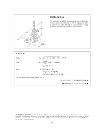
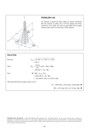
![PROPRIETARY MATERIAL. © 2010 The McGraw-Hill Companies, Inc. All rights reserved. No part of this Manual may be displayed,
reproduced or distributed in any form or by any means, without the prior written permission of the publisher, or used beyond the limited
distribution to teachers and educators permitted by McGraw-Hill for their individual course preparation. If you are a student using this Manual,
you are using it without permission.
255
PROBLEM 3.97
Replace the 150-N force with an equivalent force-couple
system at A.
SOLUTION
Equivalence requires : (150 N)( cos 35 sin 35 )
(122.873 N) (86.036 N)
Σ = − ° − °
= − −
F F j k
j k
/:A D AΣ = ×M M r F
where / (0.18 m) (0.12 m) (0.1 m)D A = − +r i j k
Then 0.18 0.12 0.1 N m
0 122.873 86.036
[( 0.12)( 86.036) (0.1)( 122.873)]
[ (0.18)( 86.036)]
[(0.18)( 122.873)]
(22.6 N m) (15.49 N m) (22.1 N m)
= − ⋅
− −
= − − − −
+ − −
+ −
= ⋅ + ⋅ − ⋅
i j k
M
i
j
k
i j k
The equivalent force-couple system at A is
(122.9 N) (86.0 N)= − −F j k W
(22.6 N m) (15.49 N m) (22.1 N m)= ⋅ + ⋅ − ⋅M i j k W](https://image.slidesharecdn.com/mecanica-151208044028-lva1-app6892/85/Mecanica-253-320.jpg)
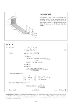
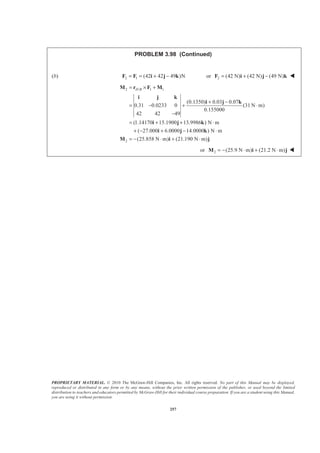
![PROPRIETARY MATERIAL. © 2010 The McGraw-Hill Companies, Inc. All rights reserved. No part of this Manual may be displayed,
reproduced or distributed in any form or by any means, without the prior written permission of the publisher, or used beyond the limited
distribution to teachers and educators permitted by McGraw-Hill for their individual course preparation. If you are a student using this Manual,
you are using it without permission.
258
PROBLEM 3.99
A 46-lb force F and a 2120-lb ⋅ in. couple M are
applied to corner A of the block shown. Replace
the given force-couple system with an equivalent
force-couple system at corner H.
SOLUTION
We have 2 2 2
(18) ( 14) ( 3) 23 in.AJd = + − + − =
Then
46 lb
(18 14 3 )
23
(36 lb) (28 lb) (6 lb)
= − −
= − −
F i j k
i j k
Also 2 2 2
( 45) (0) ( 28) 53 in.ACd = − + + − =
Then
2120 lb in.
( 45 28 )
53
(1800 lb in.) (1120 lb in.)
⋅
= − −
= − ⋅ − ⋅
M i k
i k
Now /A H′ = + ×M M r F
where / (45 in.) (14 in.)A H = +r i j
Then ( 1800 1120 ) 45 14 0
36 28 6
′ = − − +
− −
i j k
M i k
( 1800 1120 ) {[(14)( 6)] [ (45)( 6)] [(45)( 28) (14)(36)] }
( 1800 84) (270) ( 1120 1764)
(1884 lb in.) (270 lb in.) (2884 lb in.)
(157 lb ft) (22.5 lb ft) (240 lb ft)
= − − + − + − − + − −
= − − + + − −
= − ⋅ + ⋅ − ⋅
= − ⋅ + ⋅ − ⋅
i k i j k
i j k
i j k
i j k
The equivalent force-couple system at H is (36.0 lb) (28.0 lb) (6.00 lb)′ = − −F i j k W
(157 lb ft) (22.5 lb ft) (240 lb ft)′ = − ⋅ + ⋅ − ⋅M i j k W](https://image.slidesharecdn.com/mecanica-151208044028-lva1-app6892/85/Mecanica-256-320.jpg)
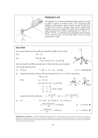

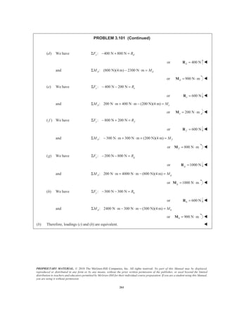
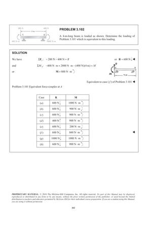
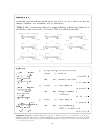
![PROPRIETARY MATERIAL. © 2010 The McGraw-Hill Companies, Inc. All rights reserved. No part of this Manual may be displayed,
reproduced or distributed in any form or by any means, without the prior written permission of the publisher, or used beyond the limited
distribution to teachers and educators permitted by McGraw-Hill for their individual course preparation. If you are a student using this Manual,
you are using it without permission.
264
PROBLEM 3.104
Five separate force-couple systems act at the corners of a piece of sheet metal, which has been bent into the
shape shown. Determine which of these systems is equivalent to a force F = (10 lb)i and a couple of moment
M = (15 lb ⋅ ft)j + (15 lb ⋅ ft)k located at the origin.
SOLUTION
First note that the force-couple system at F cannot be equivalent because of the direction of the force [The
force of the other four systems is (10 lb)i]. Next move each of the systems to the origin O; the forces remain
unchanged.
: (5 lb ft) (15 lb ft) (2 ft) (10 lb)A OA = Σ = ⋅ + ⋅ + ×M M j k k i
(25 lb ft) (15 lb ft)= ⋅ + ⋅j k
: (5 lb ft) (25 lb ft)
[(4.5 ft) (1 ft) (2 ft) ] 10 lb)
(15 lb ft) (15 lb ft)
D OD = Σ = − ⋅ + ⋅
+ + + ×
= ⋅ + ⋅
M M j k
j j k i
i k
: (15 lb ft) (15 lb ft)
: (15 lb ft) (5 lb ft)
[(4.5 ft) (1 ft) ] (10 lb)
G O
I I
G
I
= Σ = ⋅ + ⋅
= Σ = ⋅ − ⋅
+ + ×
M M i j
M M j k
i j j
(15 lb ft) (15 lb ft)= ⋅ − ⋅j k
The equivalent force-couple system is the system at corner D. W](https://image.slidesharecdn.com/mecanica-151208044028-lva1-app6892/85/Mecanica-262-320.jpg)
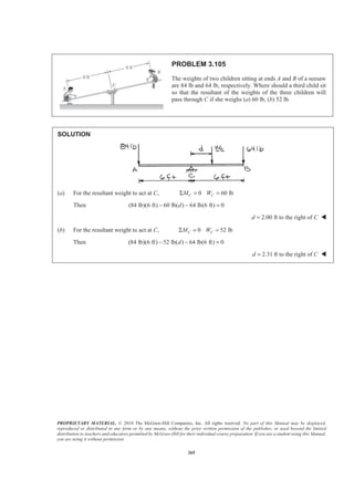
 ( in.)(11.7 lb)
DF
d L
Σ − −
− + = −
or 375.4 3.5 11.7 ( , in in.)d L d L+ =
(a) 25 in.d =
We have 375.4 3.5(25) 11.7 or 39.6 in.L L+ = =
The resultant passes through a Point 39.6 in. to the right of D. W
(b) 42 in.L =
We have 375.4 3.5 11.7(42)d+ = or 33.1 in.d = W](https://image.slidesharecdn.com/mecanica-151208044028-lva1-app6892/85/Mecanica-264-320.jpg)
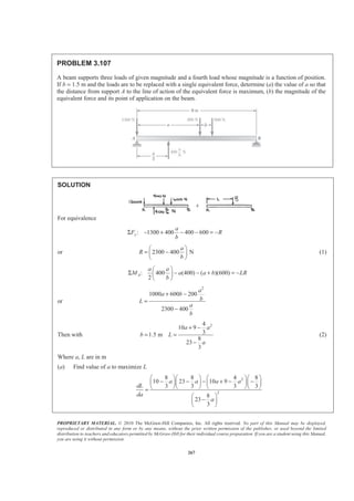
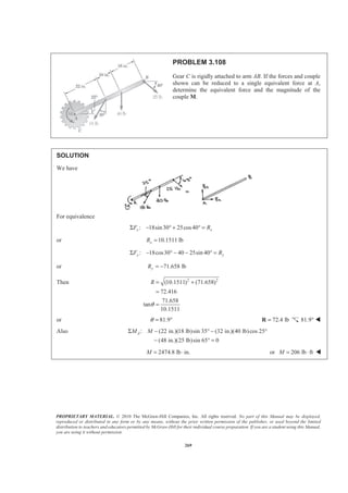
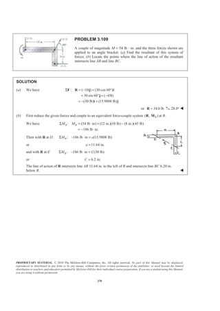
![PROPRIETARY MATERIAL. © 2010 The McGraw-Hill Companies, Inc. All rights reserved. No part of this Manual may be displayed,
reproduced or distributed in any form or by any means, without the prior written permission of the publisher, or used beyond the limited
distribution to teachers and educators permitted by McGraw-Hill for their individual course preparation. If you are a student using this Manual,
you are using it without permission.
271
PROBLEM 3.110
A couple M and the three forces shown are applied to an angle bracket.
Find the moment of the couple if the line of action of the resultant of the
force system is to pass through (a) Point A, (b) Point B, (c) Point C.
SOLUTION
In each case, must have 0R
=iM
(a) (12 in.)[(30 lb)sin 60 ] (8 in.)(45 lb) 0B
A AM M M= Σ = + ° − =
48.231 lb in.M = + ⋅ 48.2 lb in.= ⋅M W
(b) (12 in.)(10 lb) (8 in.)(45 lb) 0R
B BM M M= Σ = + − =
240 lb in.M = + ⋅ 240 lb in.= ⋅M W
(c) (12 in.)(10 lb) (8 in.)[(30 lb)cos60 ] 0R
C CM M M= Σ = + − ° =
0M = 0=M W](https://image.slidesharecdn.com/mecanica-151208044028-lva1-app6892/85/Mecanica-269-320.jpg)
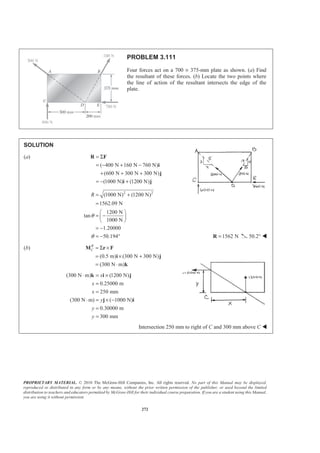
![PROPRIETARY MATERIAL. © 2010 The McGraw-Hill Companies, Inc. All rights reserved. No part of this Manual may be displayed,
reproduced or distributed in any form or by any means, without the prior written permission of the publisher, or used beyond the limited
distribution to teachers and educators permitted by McGraw-Hill for their individual course preparation. If you are a student using this Manual,
you are using it without permission.
273
PROBLEM 3.112
Solve Problem 3.111, assuming that the 760-N force is directed
to the right.
PROBLEM 3.111 Four forces act on a 700 × 375-mm plate as
shown. (a) Find the resultant of these forces. (b) Locate the two
points where the line of action of the resultant intersects the edge
of the plate.
SOLUTION
(a)
( 400N 160 N 760 N)
(600 N 300 N 300 N)
(520 N) (1200 N)
= Σ
= − + +
+ + +
= +
R F
i
j
i j
2 2
(520 N) (1200 N) 1307.82 N
1200 N
tan 2.3077
520 N
66.5714
R
θ
θ
= + =
§ ·
= =¨ ¸
© ¹
= ° 1308 N=R 66.6° W
(b)
(0.5 m) (300 N 300 N)
(300 N m)
R
C = Σ ×
= × +
= ⋅
M r F
i j
k
(300 N m) (1200 N)
0.25000 m
x
x
⋅ = ×
=
k i j
or 0.250 mmx =
(300 N m) [ (0.375 m) ] [(520 N) (1200 N) ]
(1200 195)
x
x
′⋅ = + × +
′= −
k i j i j
k
0.41250 mx′ =
or 412.5 mmx′ =
Intersection 412 mm to the right of A and 250 mm to the right of C W](https://image.slidesharecdn.com/mecanica-151208044028-lva1-app6892/85/Mecanica-271-320.jpg)
 [240 lbsin 70 ](4 ft)
(160 lb)(12 ft) [300 lbcos40 ](6 ft)
[300 lbsin 40 ](20 ft) (180 lb)(8 ft)
7232.5 lb ft
AMΣ = − ° − °
− + °
− ° −
= − ⋅
7232.5 lb ft
758.36 lb
9.5370 ft
d
− ⋅
=
−
= or 9.54 ft to the right ofd A= W](https://image.slidesharecdn.com/mecanica-151208044028-lva1-app6892/85/Mecanica-272-320.jpg)
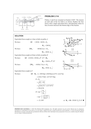

[(360 lb)sin 25 ](12 in.) 90 lb in.
− °
+ ° − ⋅
(350.56 lb in.)F = − ⋅M k
To determine where a single resultant force will intersect line FE,
350.56 lb in.
127 857 lb
2.7418 in.
F y
F
y
M dR
M
d
R
=
=
− ⋅
=
− ⋅
= or 2.74 in.d = W](https://image.slidesharecdn.com/mecanica-151208044028-lva1-app6892/85/Mecanica-274-320.jpg)
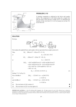
![PROPRIETARY MATERIAL. © 2010 The McGraw-Hill Companies, Inc. All rights reserved. No part of this Manual may be displayed,
reproduced or distributed in any form or by any means, without the prior written permission of the publisher, or used beyond the limited
distribution to teachers and educators permitted by McGraw-Hill for their individual course preparation. If you are a student using this Manual,
you are using it without permission.
278
PROBLEM 3.116
Solve Problem 3.115, assuming that P = 60 N.
PROBLEM 3.115 A machine component is subjected to the
forces and couples shown. The component is to be held in
place by a single rivet that can resist a force but not a couple.
For P = 0, determine the location of the rivet hole if it is to
be located (a) on line FG, (b) on line GH.
SOLUTION
See the solution to Problem 3.115 leading to the development of Equation (1)
and
(55.544 0.13 ) N m
(152.142 ) N
G
x
M P
R P
= − + ⋅
= +
For 60 NP =
We have (152.142 60)
212.14 N
[55.544 0.13(60)]
63.344 N m
x
G
R
M
= +
=
= − +
= − ⋅
Then with R at I : 63.344 N m (244.53 N)GM aΣ − ⋅ = −
or 0.259 ma =
and with R at J : 63.344 N m (212.14 N)GM bΣ − ⋅ = −
or 0.299 mb =
(a) The rivet hole is 0.299 m above G. W
(b) The rivet hole is 0.259 m to the right of G. W](https://image.slidesharecdn.com/mecanica-151208044028-lva1-app6892/85/Mecanica-276-320.jpg)
![PROPRIETARY MATERIAL. © 2010 The McGraw-Hill Companies, Inc. All rights reserved. No part of this Manual may be displayed,
reproduced or distributed in any form or by any means, without the prior written permission of the publisher, or used beyond the limited
distribution to teachers and educators permitted by McGraw-Hill for their individual course preparation. If you are a student using this Manual,
you are using it without permission.
279
PROBLEM 3.117
A 32-lb motor is mounted on the floor. Find the resultant of the
weight and the forces exerted on the belt, and determine where
the line of action of the resultant intersects the floor.
SOLUTION
We have
: (60 lb) (32 lb) (140 lb)(cos30 sin30 )Σ − + ° + ° =F i j i j R
(181.244 lb) (38.0 lb)= +R i j
or 185.2 lb=R 11.84° W
We have :O O yM M xRΣ Σ =
[(140 lb)cos30 ][(4 2cos30 )in.] [(140 lb)sin30 ][(2 in.)sin30 ]− ° + ° − ° °
(60 lb)(2 in.) (38.0 lb)x− =
1
( 694.97 70.0 120) in.
38.0
x = − − −
and 23.289 in.x = −
Or, resultant intersects the base (x axis) 23.3 in. to the left of
the vertical centerline (y axis) of the motor. W](https://image.slidesharecdn.com/mecanica-151208044028-lva1-app6892/85/Mecanica-277-320.jpg)
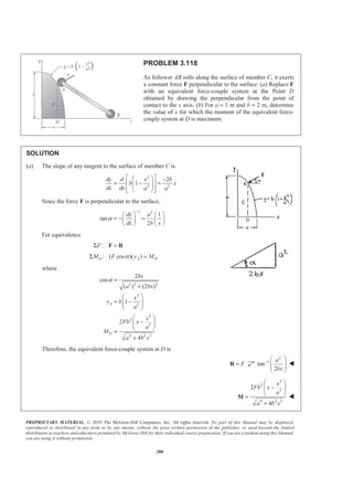
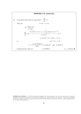
![PROPRIETARY MATERIAL. © 2010 The McGraw-Hill Companies, Inc. All rights reserved. No part of this Manual may be displayed,
reproduced or distributed in any form or by any means, without the prior written permission of the publisher, or used beyond the limited
distribution to teachers and educators permitted by McGraw-Hill for their individual course preparation. If you are a student using this Manual,
you are using it without permission.
282
PROBLEM 3.119
Four forces are applied to the machine component
ABDE as shown. Replace these forces by an equivalent
force-couple system at A.
SOLUTION
(50 N) (300 N) (120 N) (250 N)
(420 N) (50 N) (250 N)
(0.2 m)
(0.2 m) (0.16 m)
(0.2 m) (0.1 m) (0.16 m)
B
D
E
= − − − −
= − − −
=
= +
= − +
R j i i k
R i j k
r i
r ki
r i j k
[ (300 N) (50 N) ]
( 250 N) ( 120 N)
0.2 m 0 0 0.2 m 0 0.16 m
300 N 50 N 0 0 0 250 N
0.2 m 0.1 m 0.16 m
120 N 0 0
(10 N m) (50 N m) (19.2 N m) (12 N m)
R
A B
D
= × − −
+ × − + × −
= +
− − −
+ −
−
= − ⋅ + ⋅ − ⋅ − ⋅
M r i j
r k r i
i j k i j k
i j k
k j j k
Force-couple system at A is
(420 N) (50 N) (250 N) (30.8 N m) (220 N m)R
A= − − − = ⋅ − ⋅R i j k M j k W](https://image.slidesharecdn.com/mecanica-151208044028-lva1-app6892/85/Mecanica-280-320.jpg)
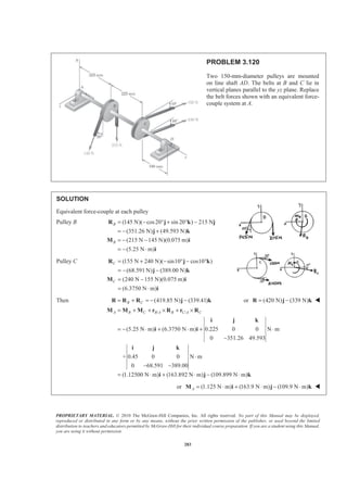
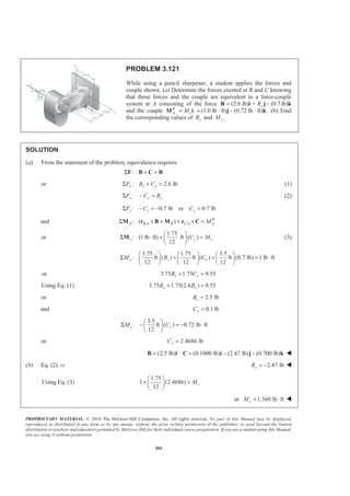
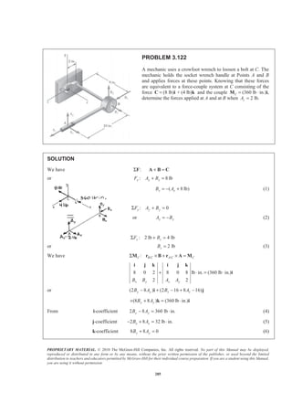
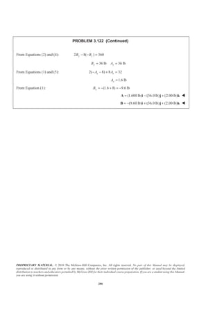
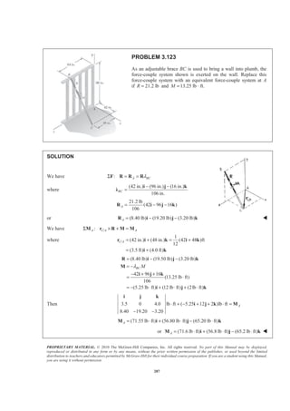
![PROPRIETARY MATERIAL. © 2010 The McGraw-Hill Companies, Inc. All rights reserved. No part of this Manual may be displayed,
reproduced or distributed in any form or by any means, without the prior written permission of the publisher, or used beyond the limited
distribution to teachers and educators permitted by McGraw-Hill for their individual course preparation. If you are a student using this Manual,
you are using it without permission.
288
PROBLEM 3.124
A mechanic replaces a car’s exhaust system by firmly clamping the catalytic converter FG to its mounting
brackets H and I and then loosely assembling the mufflers and the exhaust pipes. To position the tailpipe AB,
he pushes in and up at A while pulling down at B. (a) Replace the given force system with an equivalent
force-couple system at D. (b) Determine whether pipe CD tends to rotate clockwise or counterclockwise
relative to muffler DE, as viewed by the mechanic.
SOLUTION
(a) Equivalence requires
:Σ = +F R A B
(100 N)(cos 30 sin 30 ) (115 N)
(28.4 N) (50 N)
= ° − ° −
= − −
j k j
j k
and :D D A D A B D BΣ = × + ×/ /M M r F r F
where /
/
(0.48 m) (0.225 m) (1.12 m)
(0.38 m) (0.82 m)
A D
B D
= − − +
= − +
r i j k
r i k
Then
100 0.48 0.225 1.12 115 0.38 0 0.82
0 cos30 sin30 0 1 0
D = − − + −
° − ° −
i j k i j k
M
100[(0.225sin 30 1.12cos 30 ) ( 0.48sin 30 )
( 0.48cos 30 ) ] 115[(0.82) (0.38) ]
8.56 24.0 2.13
= ° − ° + − °
+ − ° + +
= − +
i j
k i k
i j k](https://image.slidesharecdn.com/mecanica-151208044028-lva1-app6892/85/Mecanica-286-320.jpg)
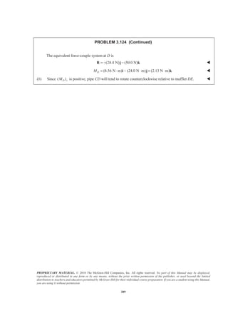
![PROPRIETARY MATERIAL. © 2010 The McGraw-Hill Companies, Inc. All rights reserved. No part of this Manual may be displayed,
reproduced or distributed in any form or by any means, without the prior written permission of the publisher, or used beyond the limited
distribution to teachers and educators permitted by McGraw-Hill for their individual course preparation. If you are a student using this Manual,
you are using it without permission.
290
PROBLEM 3.125
For the exhaust system of Problem 3.124, (a) replace the given force system with an equivalent force-couple
system at F, where the exhaust pipe is connected to the catalytic converter, (b) determine whether pipe EF
tends to rotate clockwise or counterclockwise, as viewed by the mechanic.
SOLUTION
(a) Equivalence requires
:Σ = +F R A B
(100 N)(cos30 sin30 ) (115 N)
(28.4 N) (50 N)
= ° − ° −
= − −
j k j
j k
and :F F A F B F= × + ×/ /M M r A r B
where /
/
(0.48 m) (0.345 m) (2.10 m)
(0.38 m) (0.12 m) (1.80 m)
A F
B F
= − − +
= − − +
r i j k
r i j k
Then
100 0.48 0.345 2.10 115 0.38 0.12 1.80
0 cos 30 sin 30 0 1 0
F = − − + −
° − ° −
i j k i j k
M
100[(0.345 sin 30 2.10 cos 30 ) ( 0.48 sin 30 )
( 0.48 cos 30 ) ] 115[(1.80) (0.38) ]
42.4 24.0 2.13
F = ° − ° + − °
+ − ° + +
= − +
M i j
k i k
i j k](https://image.slidesharecdn.com/mecanica-151208044028-lva1-app6892/85/Mecanica-288-320.jpg)

![PROPRIETARY MATERIAL. © 2010 The McGraw-Hill Companies, Inc. All rights reserved. No part of this Manual may be displayed,
reproduced or distributed in any form or by any means, without the prior written permission of the publisher, or used beyond the limited
distribution to teachers and educators permitted by McGraw-Hill for their individual course preparation. If you are a student using this Manual,
you are using it without permission.
292
PROBLEM 3.126
The head-and-motor assembly of a radial drill press was originally
positioned with arm AB parallel to the z axis and the axis of the
chuck and bit parallel to the y axis. The assembly was then rotated
25° about the y axis and 20° about the centerline of the horizontal
arm AB, bringing it into the position shown. The drilling process
was started by switching on the motor and rotating the handle to
bring the bit into contact with the workpiece. Replace the force
and couple exerted by the drill press with an equivalent force-
couple system at the center O of the base of the vertical column.
SOLUTION
We have (11lb)[(sin 20 cos25 )] (cos20 ) (sin 20 sin 25 ) ]
(3.4097 lb) (10.3366 lb) (1.58998 lb)
= = ° ° − ° − ° °
= − −
R F i j k
i j k
or (3.41lb) (10.34 lb) (1.590 lb)= − −R i j k W
We have /O B O C= × ×M r F M
where
/ [(14 in.)sin 25 ] (15 in.) [(14 in.)cos25 ]
(5.9167 in.) (15 in.) (12.6883 in.)
(90 lb in.)[(sin 20 cos25 ) (cos20 ) (sin 20 sin 25 ) ]
(27.898 lb in.) (84.572 lb in.) (13.0090 lb in.)
B O
C
= ° + + °
= + +
= ⋅ ° ° − ° − ° °
= ⋅ − ⋅ − ⋅
r i j k
i j k
M i j k
i j k
5.9167 15 12.6883 lb in.
3.4097 10.3366 1.58998
O = ⋅
−
i j k
M
(27.898 84.572 13.0090) lb in.+ − − ⋅
(135.202 lb in.) (31.901lb in.) (125.313 lb in.)= ⋅ − ⋅ − ⋅i j k
or (135.2 lb in.) (31.9 lb in.) (125.3 lb in.)O = ⋅ − ⋅ − ⋅M i j k W](https://image.slidesharecdn.com/mecanica-151208044028-lva1-app6892/85/Mecanica-290-320.jpg)
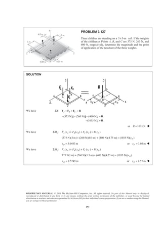
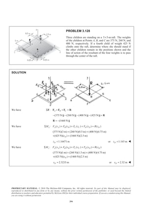
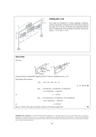
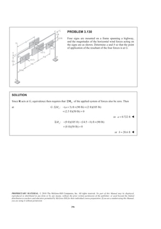
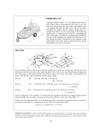
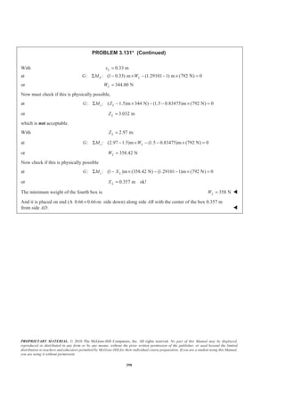
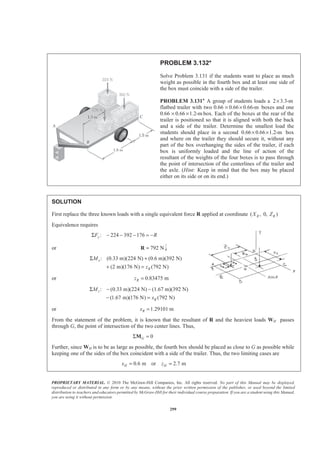
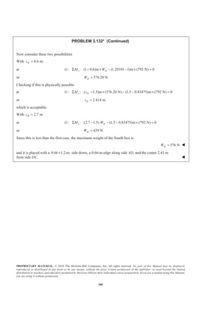
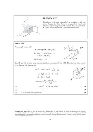
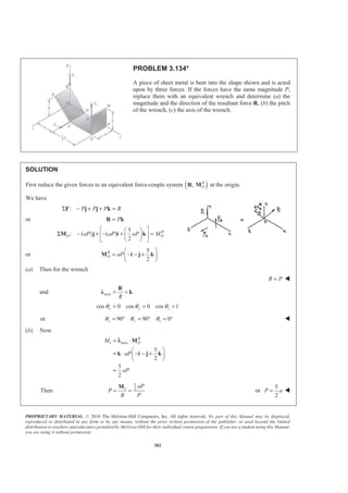
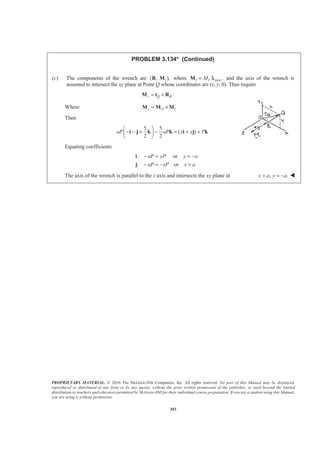
![PROPRIETARY MATERIAL. © 2010 The McGraw-Hill Companies, Inc. All rights reserved. No part of this Manual may be displayed,
reproduced or distributed in any form or by any means, without the prior written permission of the publisher, or used beyond the limited
distribution to teachers and educators permitted by McGraw-Hill for their individual course preparation. If you are a student using this Manual,
you are using it without permission.
304
PROBLEM 3.135*
The forces and couples shown are applied to two screws as a piece
of sheet metal is fastened to a block of wood. Reduce the forces and
the couples to an equivalent wrench and determine (a) the resultant
force R, (b) the pitch of the wrench, (c) the point where the axis of
the wrench intersects the xz plane.
SOLUTION
First, reduce the given force system to a force-couple system.
We have : (20 N) (15 N) 25 NRΣ − − = =F i j R
We have : ( ) R
O O C OΣ Σ × + Σ =M r F M M
20 N(0.1 m) (4 N m) (1 N m)
(4 N m) (3 N m)
R
O = − − ⋅ − ⋅
= − ⋅ − ⋅
M j i j
i j
(a) (20.0 N) (15.0 N)= − −R i j W
(b) We have 1
( 0.8 0.6 ) [ (4 N m)] (3 N m) ]
5 N m
R
R OM
R
λ λ= ⋅ =
= − − ⋅ − ⋅ − ⋅
= ⋅
R
M
i j i j
Pitch 1 5 N m
0.200 m
25 N
M
p
R
⋅
= = =
or 0.200 mp = W
(c) From above note that
1
R
O=M M
Therefore, the axis of the wrench goes through the origin. The line of action of the wrench lies in the xy
plane with a slope of
3
4
y x= W](https://image.slidesharecdn.com/mecanica-151208044028-lva1-app6892/85/Mecanica-302-320.jpg)
![PROPRIETARY MATERIAL. © 2010 The McGraw-Hill Companies, Inc. All rights reserved. No part of this Manual may be displayed,
reproduced or distributed in any form or by any means, without the prior written permission of the publisher, or used beyond the limited
distribution to teachers and educators permitted by McGraw-Hill for their individual course preparation. If you are a student using this Manual,
you are using it without permission.
305
PROBLEM 3.136*
The forces and couples shown are applied to two screws as a piece
of sheet metal is fastened to a block of wood. Reduce the forces and
the couples to an equivalent wrench and determine (a) the resultant
force R, (b) the pitch of the wrench, (c) the point where the axis of
the wrench intersects the xz plane.
SOLUTION
First, reduce the given force system to a force-couple at the origin.
We have : (10 lb) (11lb)Σ − − =F j j R
(21lb)= −R j
We have : ( ) R
O O C OΣ Σ × + Σ =M r F M M
0 0 20 lb in. 0 0 15 lb in. (12 lb in)
0 10 0 0 11 0
(35 lb in.) (12 lb in.)
R
O = ⋅ + − ⋅ − ⋅
− −
= ⋅ − ⋅
i j k i j k
M j
i j
(a) (21lb)= −R j or (21.0 lb)= −R j W
(b) We have 1
1
( ) [(35 lb in.) (12 lb in.) ]
12 lb in. and (12 lb in.)
R
R O RM
R
= ⋅ =
= − ⋅ ⋅ − ⋅
= ⋅ = − ⋅
R
Ȝ M Ȝ
j i j
M j
and pitch 1 12 lb in.
0.57143 in.
21lb
M
p
R
⋅
= = = or 0.571in.p = W](https://image.slidesharecdn.com/mecanica-151208044028-lva1-app6892/85/Mecanica-303-320.jpg)
![PROPRIETARY MATERIAL. © 2010 The McGraw-Hill Companies, Inc. All rights reserved. No part of this Manual may be displayed,
reproduced or distributed in any form or by any means, without the prior written permission of the publisher, or used beyond the limited
distribution to teachers and educators permitted by McGraw-Hill for their individual course preparation. If you are a student using this Manual,
you are using it without permission.
306
PROBLEM 3.136* (Continued)
(c) We have 1 2
2 1 (35 lb in.)
R
O
R
O
= +
= − = ⋅
M M M
M M M i
Require 2 /
(35 lb in.) ( ) [ (21lb) ]
35 (21 ) (21 )
Q O
x z
x z
= ×
⋅ = + × −
= − +
M r R
i i k j
i k i
From i: 35 21
1.66667 in.
z
z
=
=
From k: 0 21
0
x
z
= −
=
The axis of the wrench is parallel to the y axis and intersects the xz plane at 0, 1.667 in.x z= = W](https://image.slidesharecdn.com/mecanica-151208044028-lva1-app6892/85/Mecanica-304-320.jpg)
![PROPRIETARY MATERIAL. © 2010 The McGraw-Hill Companies, Inc. All rights reserved. No part of this Manual may be displayed,
reproduced or distributed in any form or by any means, without the prior written permission of the publisher, or used beyond the limited
distribution to teachers and educators permitted by McGraw-Hill for their individual course preparation. If you are a student using this Manual,
you are using it without permission.
307
PROBLEM 3.137*
Two bolts at A and B are tightened by applying the forces
and couples shown. Replace the two wrenches with a
single equivalent wrench and determine (a) the resultant
R, (b) the pitch of the single equivalent wrench, (c) the
point where the axis of the wrench intersects the xz plane.
SOLUTION
First, reduce the given force system to a force-couple at the origin.
We have : (84 N) (80 N) 116 NRΣ − − = =F j k R
and : ( ) R
O O C OΣ Σ × + Σ =M r F M M
0.6 0 .1 0.4 0.3 0 ( 30 32 )N m
0 84 0 0 0 80
R
O+ + − − ⋅ =
i j k i j k
j k M
(15.6 N m) (2 N m) (82.4 N m)R
O = − ⋅ + ⋅ − ⋅M i j k
(a) (84.0 N) (80.0 N)= − −R j k W
(b) We have 1
84 80
[ (15.6 N m) (2 N m) (82.4 N m) ]
116
55.379 N m
R
R O RM
R
= ⋅ =
− −
= − ⋅ − ⋅ + ⋅ − ⋅
= ⋅
R
Ȝ M Ȝ
j k
i j k
and 1 1 (40.102 N m) (38.192 N m)RM λ= = − ⋅ − ⋅M j k
Then pitch 1 55.379 N m
0.47741 m
116 N
M
p
R
⋅
= = = or 0.477 mp = W](https://image.slidesharecdn.com/mecanica-151208044028-lva1-app6892/85/Mecanica-305-320.jpg)
![PROPRIETARY MATERIAL. © 2010 The McGraw-Hill Companies, Inc. All rights reserved. No part of this Manual may be displayed,
reproduced or distributed in any form or by any means, without the prior written permission of the publisher, or used beyond the limited
distribution to teachers and educators permitted by McGraw-Hill for their individual course preparation. If you are a student using this Manual,
you are using it without permission.
308
PROBLEM 3.137* (Continued)
(c) We have 1 2
2 1 [( 15.6 2 82.4 ) (40.102 38.192 )] N m
(15.6 N m) (42.102 N m) (44.208 N m)
R
O
R
O
= +
= − = − + − − − ⋅
= − ⋅ + ⋅ − ⋅
M M M
M M M i j k j k
i j k
Require 2 /
( 15.6 42.102 44.208 ) ( ) (84 80 )
(84 ) (80 ) (84 )
Q O
x z
z x x
= ×
− + − = + × −
= + −
M r R
i j k i k j k
i j k
From i: 15.6 84
0.185714 m
z
z
− =
= −
or 0.1857 mz = −
From k: 44.208 84
0.52629 m
x
x
− = −
=
or 0.526 mx =
The axis of the wrench intersects the xz plane at
0.526 m 0 0.1857 mx y z= = = − W](https://image.slidesharecdn.com/mecanica-151208044028-lva1-app6892/85/Mecanica-306-320.jpg)
![PROPRIETARY MATERIAL. © 2010 The McGraw-Hill Companies, Inc. All rights reserved. No part of this Manual may be displayed,
reproduced or distributed in any form or by any means, without the prior written permission of the publisher, or used beyond the limited
distribution to teachers and educators permitted by McGraw-Hill for their individual course preparation. If you are a student using this Manual,
you are using it without permission.
309
PROBLEM 3.138*
Two bolts at A and B are tightened by applying the forces and
couples shown. Replace the two wrenches with a single equivalent
wrench and determine (a) the resultant R, (b) the pitch of the
single equivalent wrench, (c) the point where the axis of the
wrench intersects the xz plane.
SOLUTION
First, reduce the given force system to a force-couple at the origin at B.
(a) We have
8 15
: (26.4 lb) (17 lb)
17 17
§ ·
Σ − − + =¨ ¸
© ¹
F k i j R
(8.00 lb) (15.00 lb) (26.4 lb)= − − −R i j k W
and 31.4 lbR =
We have /: R
B A B A A B BΣ × + + =M r F M M M
8 15
0 10 0 220 238 264 220 14(8 15 )
17 17
0 0 26.4
(152 lb in.) (210 lb in.) (220 lb in.)
R
B
R
B
§ ·
= − − − + = − − +¨ ¸
© ¹
−
= ⋅ − ⋅ − ⋅
i j k
M k i j i k i j
M i j k
(b) We have 1
8.00 15.00 26.4
[(152 lb in.) (210 lb in.) (220 lb in.) ]
31.4
246.56 lb in.
R
R O RM
R
= ⋅ =
− − −
= ⋅ ⋅ − ⋅ − ⋅
= ⋅
R
Ȝ M Ȝ
i j k
i j k](https://image.slidesharecdn.com/mecanica-151208044028-lva1-app6892/85/Mecanica-307-320.jpg)
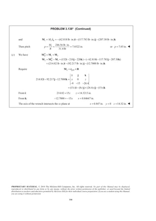
![PROPRIETARY MATERIAL. © 2010 The McGraw-Hill Companies, Inc. All rights reserved. No part of this Manual may be displayed,
reproduced or distributed in any form or by any means, without the prior written permission of the publisher, or used beyond the limited
distribution to teachers and educators permitted by McGraw-Hill for their individual course preparation. If you are a student using this Manual,
you are using it without permission.
311
PROBLEM 3.139*
Two ropes attached at A and B are used to move the trunk of a
fallen tree. Replace the forces exerted by the ropes with an
equivalent wrench and determine (a) the resultant force R,
(b) the pitch of the wrench, (c) the point where the axis of the
wrench intersects the yz plane.
SOLUTION
(a) First replace the given forces with an equivalent force-couple system ( ), R
OR M at the origin.
We have
2 2 2
2 2 2
(6) (2) (9) 11 m
(14) (2) (5) 15 m
AC
BD
d
d
= + + =
= + + =
Then
1650 N
(6 2 9 )
11
(900 N) (300 N) (1350 N)
ACT = = + +
= + +
i j k
i j k
and
1500 N
(14 2 5 )
15
(1400 N) (200 N) (500 N)
BDT = = + +
= + +
i j k
i j k
Equivalence then requires
:
(900 300 1350 )
(1400 200 500 )
(2300 N) (500 N) (1850 N)
AC BDΣ = +
= + +
+ + +
= + +
F R T T
i j k
i j k
i j k
: R
O O A AC B BDΣ = × + ×M M r T r T
(12 m) [(900 N) (300 N) (1350 N) ]
(9 m) [(1400 N) (200 N) (500 N) ]
(3600) (10800 4500) (1800)
(3600 N m) (6300 N m) (1800 N m)
= × + +
+ × + +
= − + − +
= − ⋅ + ⋅ + ⋅
k i j k
i i j k
i j k
i j k
The components of the wrench are 1( , ),R M where
(2300 N) (500 N) (1850 N)= + +R i j k W](https://image.slidesharecdn.com/mecanica-151208044028-lva1-app6892/85/Mecanica-309-320.jpg)
![PROPRIETARY MATERIAL. © 2010 The McGraw-Hill Companies, Inc. All rights reserved. No part of this Manual may be displayed,
reproduced or distributed in any form or by any means, without the prior written permission of the publisher, or used beyond the limited
distribution to teachers and educators permitted by McGraw-Hill for their individual course preparation. If you are a student using this Manual,
you are using it without permission.
312
PROBLEM 3.139* (Continued)
(b) We have
2 2 2
100 (23) (5) (18.5) 2993.7 NR = + + =
Let
axis
1
(23 5 18.5 )
29.937R
= = + +
R
i j kλ
Then 1 axis
1
(23 5 18.5 ) ( 3600 6300 1800 )
29.937
1
[(23)( 36) (5)(63) (18.5)(18)]
0.29937
601.26 N m
R
OM = ⋅
= + + ⋅ − + +
= − + +
= − ⋅
M
i j k i j k
λ
Finally 1 601.26 N m
2993.7 N
M
P
R
− ⋅
= =
or 0.201 mP = − W
(c) We have 1 1 axis
1
( 601.26 N m) (23 5 18.5 )
29.937
M M=
= − ⋅ × + +
Ȝ
i j k
or 1 (461.93 N m) (100.421 N m) (371.56 N m)= − ⋅ − ⋅ − ⋅M i j k
Now 2 1
( 3600 6300 1800 )
( 461.93 100.421 371.56 )
(3138.1 N m) (6400.4 N m) (2171.6 N m)
R
O= −
= − + +
− − − −
= − ⋅ + ⋅ + ⋅
M M M
i j k
i j k
i j k
For equivalence](https://image.slidesharecdn.com/mecanica-151208044028-lva1-app6892/85/Mecanica-310-320.jpg)
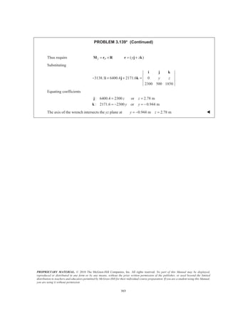
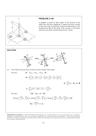
![PROPRIETARY MATERIAL. © 2010 The McGraw-Hill Companies, Inc. All rights reserved. No part of this Manual may be displayed,
reproduced or distributed in any form or by any means, without the prior written permission of the publisher, or used beyond the limited
distribution to teachers and educators permitted by McGraw-Hill for their individual course preparation. If you are a student using this Manual,
you are using it without permission.
315
PROBLEM 3.140* (Continued)
(b) We have 1
R
R OM λ= ⋅M
where
3 25 1
(2 20 ) (2 20 )
25 27 5 9 5
R
P
R P
λ = = − − = − −
R
i j k i j k
Then 1
1 24 8
(2 20 ) ( )
59 5 15 5
Pa Pa
M
−
= − − ⋅ − − =i j k i k
and pitch 1 8 25 8
8115 5 27 5
M Pa a
p
R P
§ ·− −
= = =¨ ¸
© ¹
or 0.0988p a= − W
(c) 1 1
8 1 8
(2 20 ) ( 2 20 )
67515 5 9 5
R
Pa Pa
M λ
§ ·−
= = − − = − + +¨ ¸
© ¹
M i j k i j k
Then 2 1
24 8 8
( ) ( 2 20 ) ( 430 20 406 )
5 675 675
R
O
Pa Pa Pa
= − = − − − − + + = − − −M M M i k i j k i j k
Require 2 /Q O= ×M r R
8 3
( 403 20 406 ) ( ) (2 20 )
675 25
3
[20 ( 2 ) 20 ]
25
Pa P
x z
P
z x z x
§ · § ·
− − − = + × − −¨ ¸ ¨ ¸
© ¹ © ¹
§ ·
= + + −¨ ¸
© ¹
i j k i k i j k
i j k
From i:
3
8( 403) 20 1.99012
675 25
Pa P
z z a
§ ·
− = = −¨ ¸
© ¹
From k:
3
8( 406) 20 2.0049
675 25
Pa P
x x a
§ ·
− = − =¨ ¸
© ¹
The axis of the wrench intersects the xz plane at
2.00 , 1.990x a z a= = − W](https://image.slidesharecdn.com/mecanica-151208044028-lva1-app6892/85/Mecanica-313-320.jpg)
![PROPRIETARY MATERIAL. © 2010 The McGraw-Hill Companies, Inc. All rights reserved. No part of this Manual may be displayed,
reproduced or distributed in any form or by any means, without the prior written permission of the publisher, or used beyond the limited
distribution to teachers and educators permitted by McGraw-Hill for their individual course preparation. If you are a student using this Manual,
you are using it without permission.
316
PROBLEM 3.141*
Determine whether the force-and-couple system shown can be
reduced to a single equivalent force R. If it can, determine R
and the point where the line of action of R intersects the yz
plane. If it cannot be so reduced, replace the given system with
an equivalent wrench and determine its resultant, its pitch, and
the point where its axis intersects the yz plane.
SOLUTION
First, reduce the given force system to a force-couple at the origin.
We have : A GΣ + =F F F R
(40 mm) (60 mm) (120 mm)
(50 N) 70 N
140 mm
(20 N) (30 N) (10 N)
ª º+ −
= + « »
¬ ¼
= + −
i j k
R k
i j k
and 37.417 NR =
We have : ( ) R
O O C OΣ Σ × + Σ =M r F M M
0
[(0.12 m) (50 N) ] {(0.16 m) [(20 N) (30 N) (60 N) ]}
(160 mm) (120 mm)
(10 N m)
200 mm
(40 mm) (120 mm) (60 mm)
(14 N m)
140 mm
(18 N m) (8.4 N m) (10.8 N m)
R
O
R
= × + × + −
ª º−
+ ⋅ « »
¬ ¼
ª º− +
+ ⋅ « »
¬ ¼
= ⋅ − ⋅ + ⋅
M j k i i j k
i j
i j k
M i j k
To be able to reduce the original forces and couples to a single equivalent force, R and M must be
perpendicular. Thus, 0.⋅ =R M
Substituting
?
(20 30 10 ) (18 8.4 10.8 ) 0+ − ⋅ − + =i j k i j k
or
?
(20)(18) (30)( 8.4) ( 10)(10.8) 0+ − + − =
or 0 0=
3
R and M are perpendicular so that the given system can be reduced to the single equivalent force
(20.0 N) (30.0 N) (10.00 N)= + −R i j k W](https://image.slidesharecdn.com/mecanica-151208044028-lva1-app6892/85/Mecanica-314-320.jpg)

![PROPRIETARY MATERIAL. © 2010 The McGraw-Hill Companies, Inc. All rights reserved. No part of this Manual may be displayed,
reproduced or distributed in any form or by any means, without the prior written permission of the publisher, or used beyond the limited
distribution to teachers and educators permitted by McGraw-Hill for their individual course preparation. If you are a student using this Manual,
you are using it without permission.
318
PROBLEM 3.142*
Determine whether the force-and-couple system shown can be
reduced to a single equivalent force R. If it can, determine R
and the point where the line of action of R intersects the yz
plane. If it cannot be so reduced, replace the given system with
an equivalent wrench and determine its resultant, its pitch, and
the point where its axis intersects the yz plane.
SOLUTION
First determine the resultant of the forces at D. We have
2 2 2
2 2 2
( 12) (9) (8) 17 in.
( 6) (0) ( 8) 10 in.
DA
ED
d
d
= − + + =
= − + + − =
Then
34 lb
( 12 9 8 )
17
(24 lb) (18 lb) (16 lb)
DA = = − + +
= − + +
F i j k
i j k
and
30 lb
( 6 8 )
10
(18 lb) (24 lb)
ED = = − −
= − −
F i k
i k
Then
: DA EDΣ = +F R F F
( 24 18 16 ( 18 24 )
(42 lb) (18 lb) (8 lb)
= − + + + − −
= − + −
i j k i k
i j k
For the applied couple
2 2 2
( 6) ( 6) (18) 6 11 in.AKd = − + − + =
Then
160 lb in.
( 6 6 18 )
6 11
160
[ (1 lb in.) (1 lb in.) (3 lb in.) ]
11
⋅
= − − +
= − ⋅ − ⋅ + ⋅
M i j k
i j k
To be able to reduce the original forces and couple to a single equivalent force, R and M
must be perpendicular. Thus
?
0⋅ =R M](https://image.slidesharecdn.com/mecanica-151208044028-lva1-app6892/85/Mecanica-316-320.jpg)
![PROPRIETARY MATERIAL. © 2010 The McGraw-Hill Companies, Inc. All rights reserved. No part of this Manual may be displayed,
reproduced or distributed in any form or by any means, without the prior written permission of the publisher, or used beyond the limited
distribution to teachers and educators permitted by McGraw-Hill for their individual course preparation. If you are a student using this Manual,
you are using it without permission.
319
PROBLEM 3.142* (Continued)
Substituting
?160
( 42 18 8 ) ( 3 ) 0
11
− + − ⋅ − − + =i j k i j k
or
?160
[( 42)( 1) (18)( 1) ( 8)(3)] 0
11
− − + − + − =
or 0 0=
3
R and M are perpendicular so that the given system can be reduced to the single equivalent force
(42.0 lb) (18.00 lb) (8.00 lb)= − + −R i j k W
Then for equivalence
Thus require /P D= ×M r R
where / (12 in.) [( 3)in.] ( in.)P D y z= − + − +r i j k
Substituting
160
( 3 ) 12 ( 3)
11
42 18 8
[( 3)( 8) ( )(18)]
[( )( 42) ( 12)( 8)]
[( 12)(18) ( 3)( 42)]
y z
y z
z
y
− − + = − −
− −
= − − −
+ − − − −
+ − − − −
i j k
i j k
i
j
k
Equating coefficients
160
: 42 96 or 1.137 in.
11
480
: 216 42( 3) or 11.59 in.
11
z z
y y
− = − − = −
= − + − =
j
k
The line of action of R intersects the yz plane at 0 11.59 in. 1.137 in.x y z= = = − W](https://image.slidesharecdn.com/mecanica-151208044028-lva1-app6892/85/Mecanica-317-320.jpg)

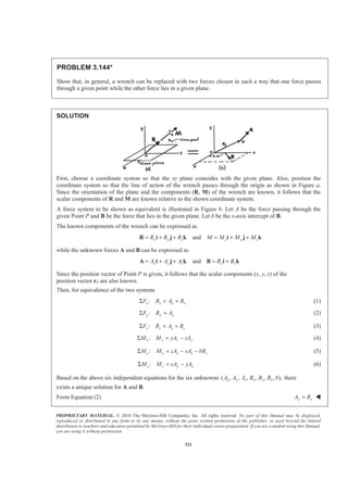
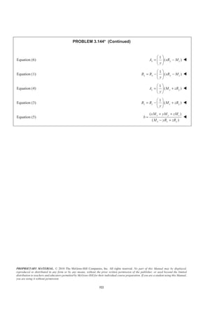
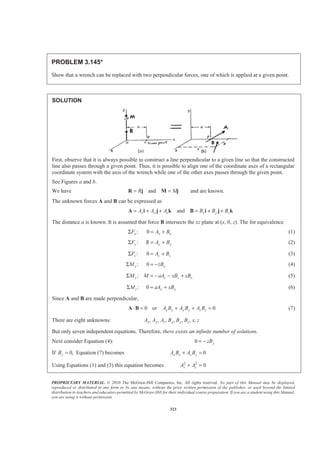
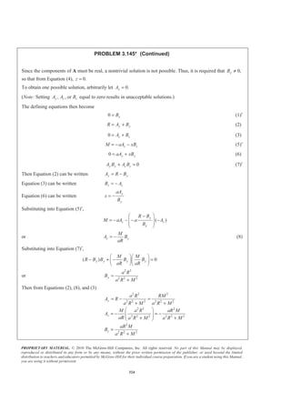
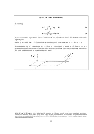
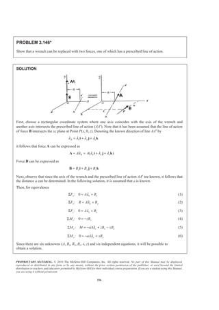
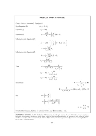

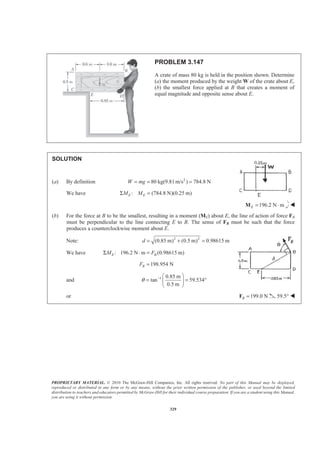
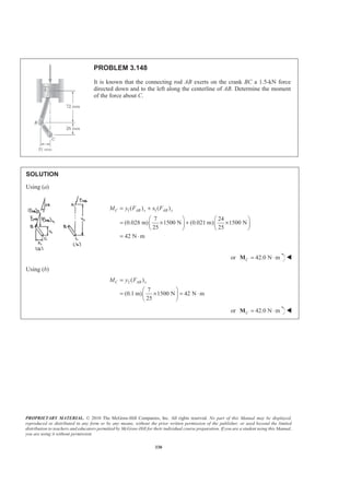
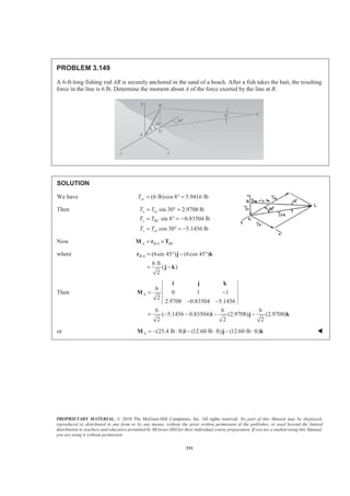
![PROPRIETARY MATERIAL. © 2010 The McGraw-Hill Companies, Inc. All rights reserved. No part of this Manual may be displayed,
reproduced or distributed in any form or by any means, without the prior written permission of the publisher, or used beyond the limited
distribution to teachers and educators permitted by McGraw-Hill for their individual course preparation. If you are a student using this Manual,
you are using it without permission.
332
PROBLEM 3.150
Ropes AB and BC are two of the ropes used to
support a tent. The two ropes are attached to a
stake at B. If the tension in rope AB is 540 N,
determine (a) the angle between rope AB and
the stake, (b) the projection on the stake of the
force exerted by rope AB at Point B.
SOLUTION
First note 2 2 2
2 2 2
( 3) (3) ( 1.5) 4.5 m
( 0.08) (0.38) (0.16) 0.42 m
BA
BD
= − + + − =
= − + + =
Then ( 3 3 1.5 )
4.5
( 2 2 )
3
1
( 0.08 0.38 0.16 )
0.42
1
( 4 19 8 )
21
BA
BA
BA
BD
T
T
BD
BD
= − + −
= − + −
= = − + +
= − + +
T i j k
i j k
i j k
i j k
λ
(a) We have cosBA BD BAT θ⋅ =T λ
or
1
( 2 2 ) ( 4 19 8 ) cos
3 21
BA
BA
T
T θ− + − ⋅ − + + =i j k i j k
or
1
cos [( 2)( 4) (2)(19) ( 1)(8)]
63
0.60317
θ = − − + + −
=
or 52.9θ = ° W
(b) We have ( )
cos
(540 N)(0.60317)
BA BD BA BD
BA
T
T θ
= ⋅
=
=
T λ
or ( ) 326 NBA BDT = W](https://image.slidesharecdn.com/mecanica-151208044028-lva1-app6892/85/Mecanica-330-320.jpg)
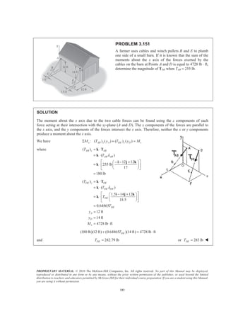
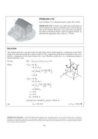
![PROPRIETARY MATERIAL. © 2010 The McGraw-Hill Companies, Inc. All rights reserved. No part of this Manual may be displayed,
reproduced or distributed in any form or by any means, without the prior written permission of the publisher, or used beyond the limited
distribution to teachers and educators permitted by McGraw-Hill for their individual course preparation. If you are a student using this Manual,
you are using it without permission.
335
PROBLEM 3.153
A wiring harness is made by routing either two or
three wires around 2-in.-diameter pegs mounted on a
sheet of plywood. If the force in each wire is 3 lb,
determine the resultant couple acting on the plywood
when a = 18 in. and (a) only wires AB and CD are in
place, (b) all three wires are in place.
SOLUTION
In general, ,M dF= Σ where d is the perpendicular distance between the lines of action of the two forces
acting on a given wire.
(a)
We have AB AB CD CDM d F d F= +
4
(2 24) in. 3 lb 2 + 28 in. 3 lb
5
§ ·
= + × + × ×¨ ¸
© ¹
or 151.2 lb in.= ⋅M W
(b)
We have [ ]AB AB CD CD EF EFM d F d F d F= + +
151.2 lb in. 28 in. 3 lb= ⋅ − × or 67.2 lb in.= ⋅M W](https://image.slidesharecdn.com/mecanica-151208044028-lva1-app6892/85/Mecanica-333-320.jpg)
![PROPRIETARY MATERIAL. © 2010 The McGraw-Hill Companies, Inc. All rights reserved. No part of this Manual may be displayed,
reproduced or distributed in any form or by any means, without the prior written permission of the publisher, or used beyond the limited
distribution to teachers and educators permitted by McGraw-Hill for their individual course preparation. If you are a student using this Manual,
you are using it without permission.
336
PROBLEM 3.154
A worker tries to move a rock by applying a 360-N force
to a steel bar as shown. (a) Replace that force with an
equivalent force-couple system at D. (b) Two workers
attempt to move the same rock by applying a vertical force
at A and another force at D. Determine these two forces if
they are to be equivalent to the single force of Part a.
SOLUTION
(a) We have : 360 N( sin 40° cos40 ) (231.40 N) (275.78 N)Σ − − ° = − − =F i j i j F
or 360N=F 50° W
We have /:D B DΣ × =M r R M
where / [(0.65 m)cos30 ] [(0.65 m)sin30 ]
(0.56292 m) (0.32500 m)
0.56292 0.32500 0 N m
231.40 275.78 0
[155.240 75.206)N m]
B D = − ° + °
= − +
= − ⋅
− −
= + ⋅
r i j
i j
i j k
M
k
(230.45 N m)= ⋅ k or 230 N m= ⋅M W
(b) We have /:D A D AΣ = ×M M r F
where / [(1.05 m)cos30 ] [(1.05 m)sin30 ]
(0.90933 m) (0.52500 m)
0.90933 0.52500 0 N m
0 1 0
[230.45 N m]
B D
AF
= − ° + °
= − +
= − ⋅
−
= ⋅
r i j
i j
i j k
k
(a) (b)](https://image.slidesharecdn.com/mecanica-151208044028-lva1-app6892/85/Mecanica-334-320.jpg)
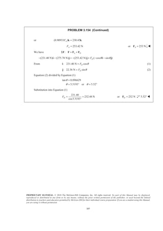
![PROPRIETARY MATERIAL. © 2010 The McGraw-Hill Companies, Inc. All rights reserved. No part of this Manual may be displayed,
reproduced or distributed in any form or by any means, without the prior written permission of the publisher, or used beyond the limited
distribution to teachers and educators permitted by McGraw-Hill for their individual course preparation. If you are a student using this Manual,
you are using it without permission.
338
PROBLEM 3.155
A 110-N force acting in a vertical plane parallel to the yz plane
is applied to the 220-mm-long horizontal handle AB of a
socket wrench. Replace the force with an equivalent force-
couple system at the origin O of the coordinate system.
SOLUTION
We have : BΣ =F P F
where 110 N[ (sin15 ) (cos15 ) ]
(28.470 N) (106.252 N)
B = − ° + °
= − +
P j k
j k
or (28.5 N) (106.3 N)= − +F j k W
We have /:O B O B OMΣ × =r P M
where / [(0.22cos35 ) (0.15) (0.22sin35 ) ]m
(0.180213 m) (0.15 m) (0.126187 m)
B O = ° + − °
= + −
r i j k
i j k
0.180213 0.15 0.126187 N m
0 28.5 106.3
O⋅ =
−
i j k
M
[(12.3487) (19.1566) (5.1361) ]N mO = − − ⋅M i j k
or (12.35 N m) (19.16 N m) (5.13 N m)O = ⋅ − ⋅ − ⋅M i j k W](https://image.slidesharecdn.com/mecanica-151208044028-lva1-app6892/85/Mecanica-336-320.jpg)
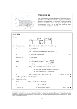
![PROPRIETARY MATERIAL. © 2010 The McGraw-Hill Companies, Inc. All rights reserved. No part of this Manual may be displayed,
reproduced or distributed in any form or by any means, without the prior written permission of the publisher, or used beyond the limited
distribution to teachers and educators permitted by McGraw-Hill for their individual course preparation. If you are a student using this Manual,
you are using it without permission.
340
PROBLEM 3.157
A blade held in a brace is used to tighten a screw at A.
(a) Determine the forces exerted at B and C, knowing
that these forces are equivalent to a force-couple
system at A consisting of (30 N) + +y zR R= −R i j k
and (12 N · m) .R
A = −M i (b) Find the corresponding
values of yR and .zR (c) What is the orientation of the
slot in the head of the screw for which the blade is least
likely to slip when the brace is in the position shown?
SOLUTION
(a) Equivalence requires :Σ = +F R B C
or (30 N) ( )y z x y zR R B C C C− + + = − + − + +i j k k i j k
Equating the i coefficients : 30 N or 30 Nx xC C− = − =i
Also / /: R
A A B A C AΣ = × + ×M M r B r C
or
(12 N m) [(0.2 m) (0.15 m) ] ( )
(0.4 m) [ (30 N) ]y z
B
C C
− ⋅ = + × −
+ × − + +
i i j k
i i j k
Equating coefficients : 12 N m (0.15 m) or 80 N
: 0 (0.4 m) or 0
: 0 (0.2 m)(80 N) (0.4 m) or 40 N
y y
z z
B B
C C
C C
− ⋅ = − =
= =
= − =
i
k
j
(80.0 N) (30.0 N) (40.0 N)= − = − +B k C i k W
(b) Now we have for the equivalence of forces
(30 N) (80 N) [( 30 N) (40 N) ]y zR R− + + = − + − +i j k k i k
Equating coefficients : 0yR =j 0yR = W
: 80 40zR = − +k or 40.0 NzR = − W
(c) First note that (30 N) (40 N) .= − −R i k Thus, the screw is best able to resist the lateral force zR
when the slot in the head of the screw is vertical. W](https://image.slidesharecdn.com/mecanica-151208044028-lva1-app6892/85/Mecanica-338-320.jpg)
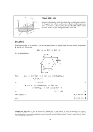

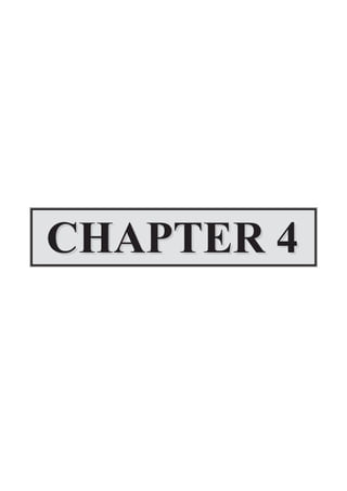

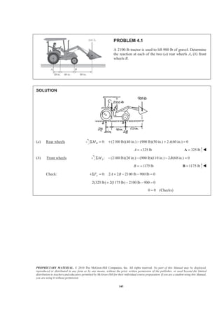
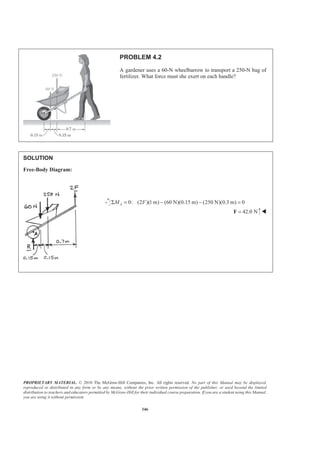
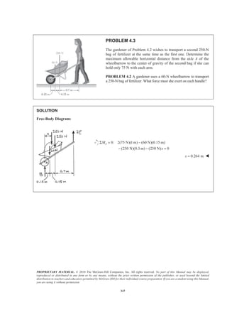
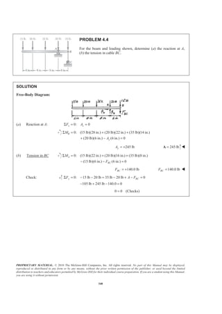
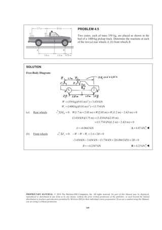
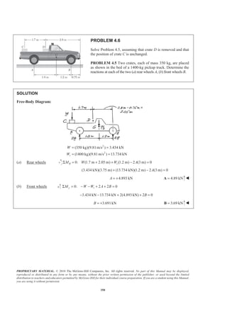
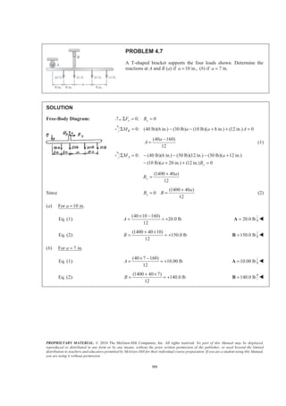
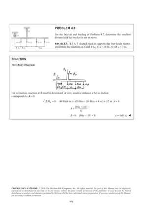
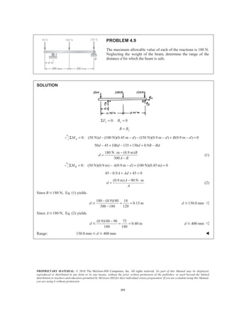
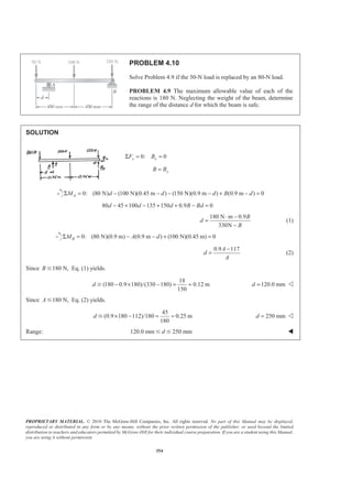
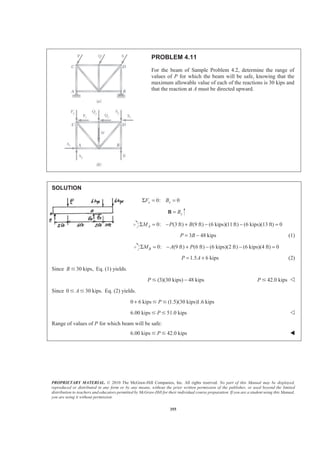
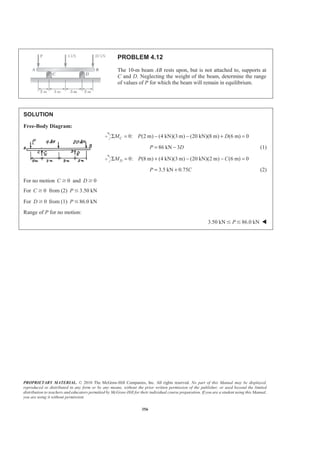
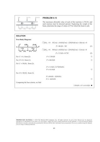
![PROPRIETARY MATERIAL. © 2010 The McGraw-Hill Companies, Inc. All rights reserved. No part of this Manual may be displayed,
reproduced or distributed in any form or by any means, without the prior written permission of the publisher, or used beyond the limited
distribution to teachers and educators permitted by McGraw-Hill for their individual course preparation. If you are a student using this Manual,
you are using it without permission.
358
PROBLEM 4.14
For the beam and loading shown, determine the range of the
distance a for which the reaction at B does not exceed 100 lb
downward or 200 lb upward.
SOLUTION
Assume B is positive when directed
Sketch showing distance from D to forces.
0: (300 lb)(8 in. ) (300 lb)( 2 in.) (50 lb)(4 in.) 16 0DM a a BΣ = − − − − + =
600 2800 16 0a B− + + =
(2800 16 )
600
B
a
+
= (1)
For 100 lbB = 100 lb,= − Eq. (1) yields:
[2800 16( 100)] 1200
2 in.
600 600
a
+ −
= =Ն 2.00 in.a Ն Y
For 200B = 200 lb,= + Eq. (1) yields:
[2800 16(200)] 6000
10 in.
600 600
a
+
= =Յ 10.00 in.a Յ Y
Required range: 2.00 in. 10.00 in.aՅ Յ W](https://image.slidesharecdn.com/mecanica-151208044028-lva1-app6892/85/Mecanica-356-320.jpg)
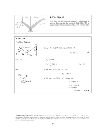
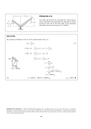
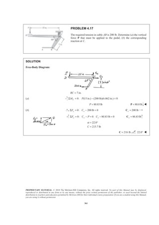
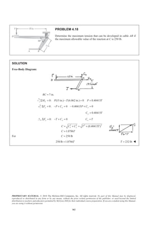
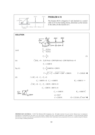
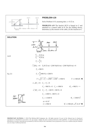
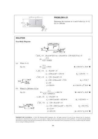
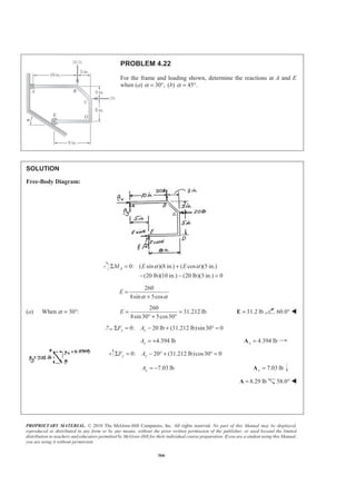
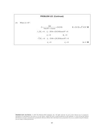
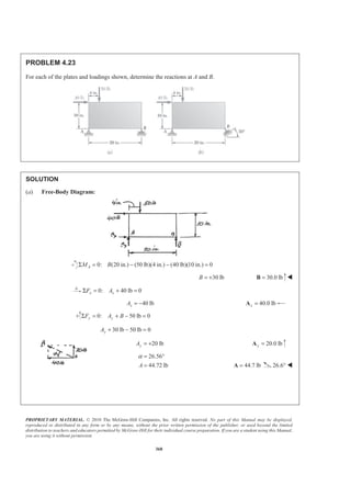
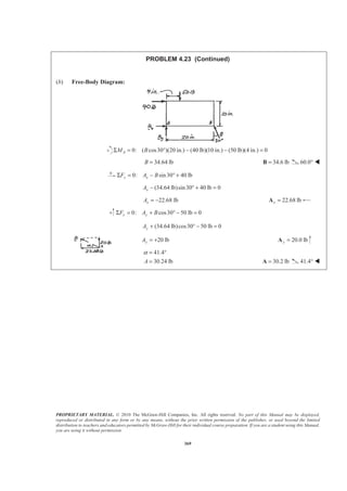
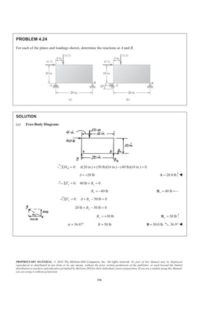
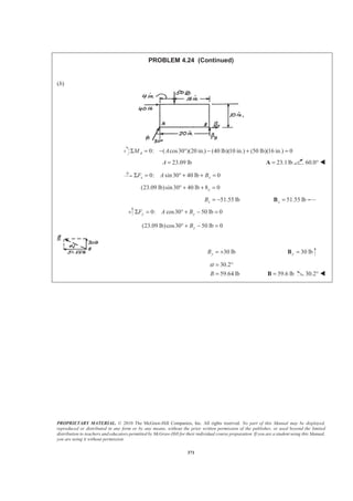
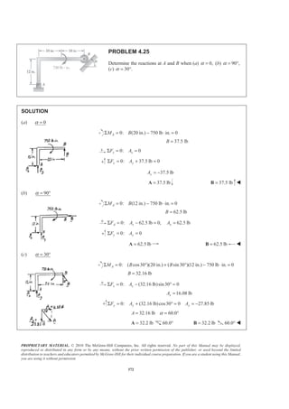
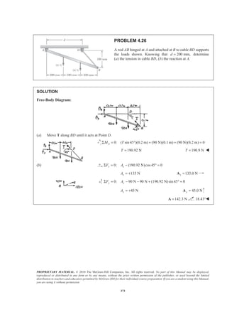
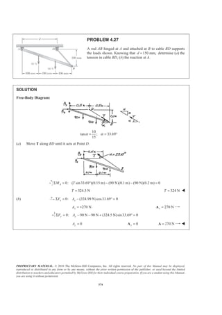
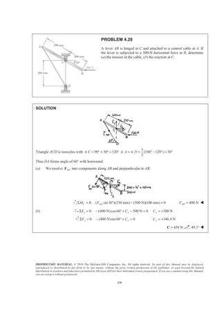
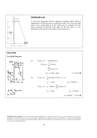
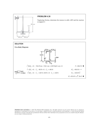
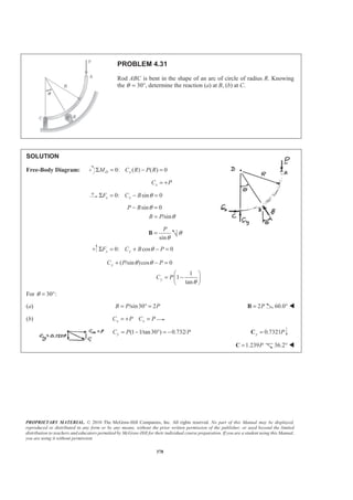
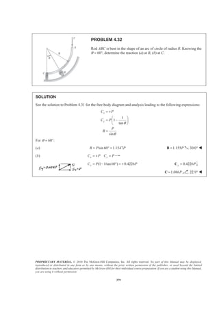
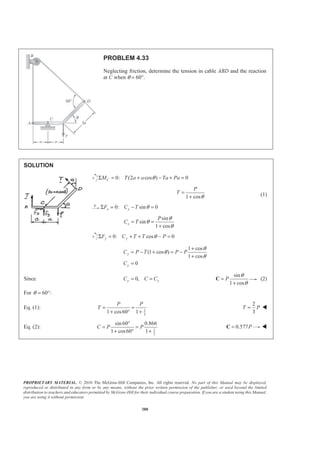
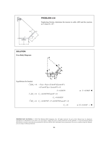
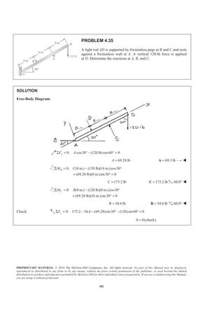
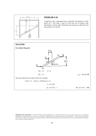
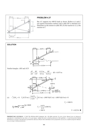
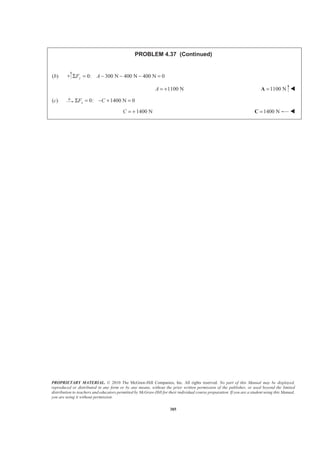
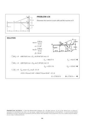
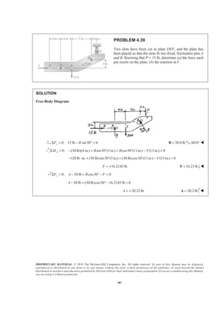
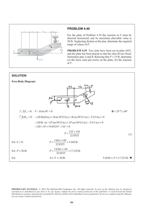
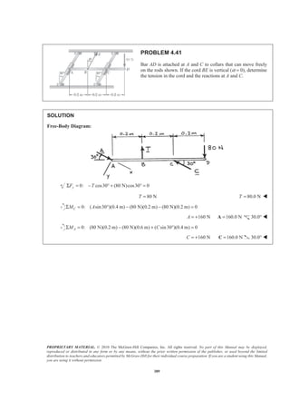
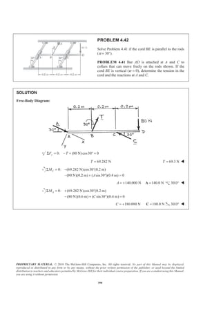
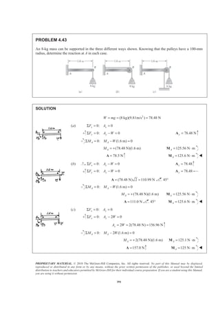
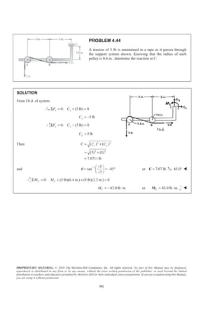
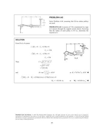
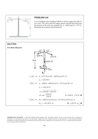
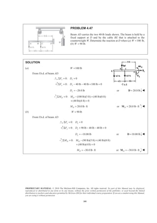
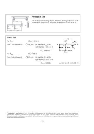
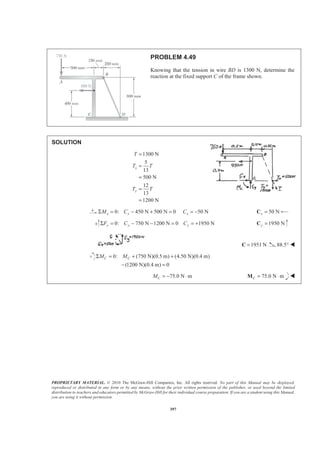
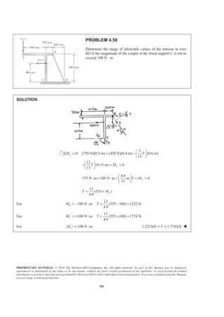
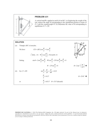
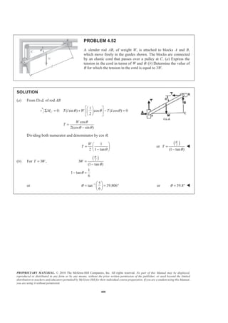

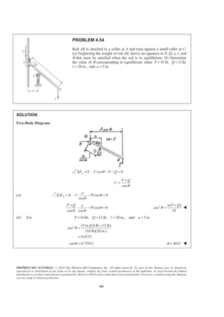
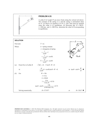
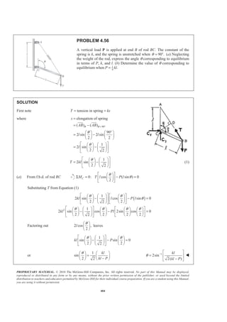
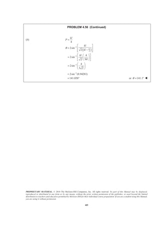
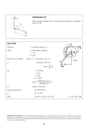
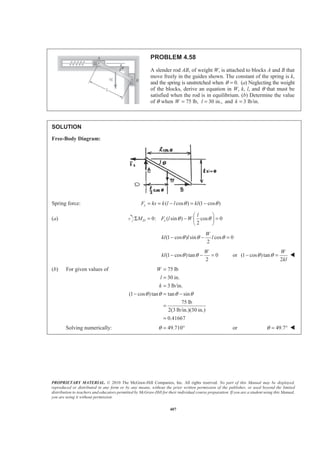
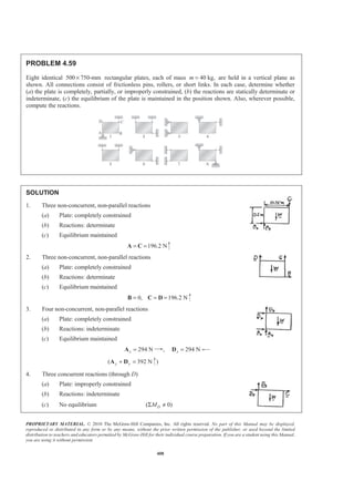
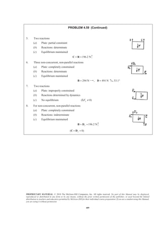
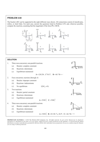
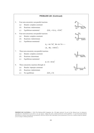
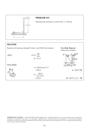
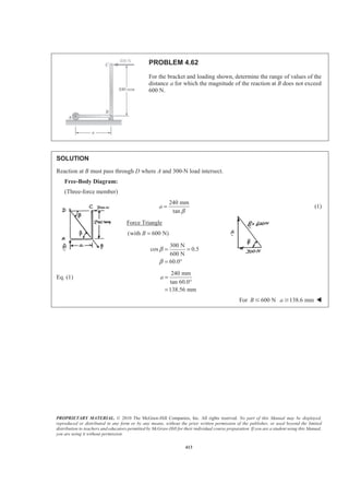
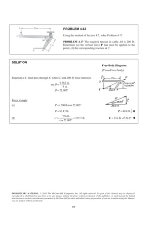
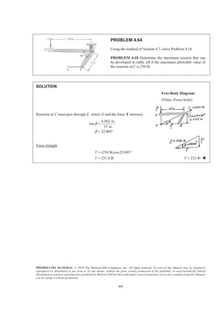
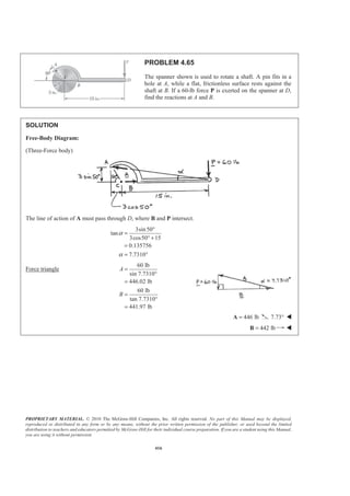
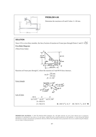
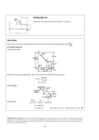
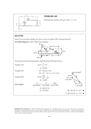
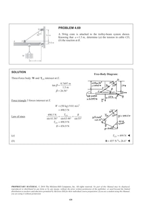
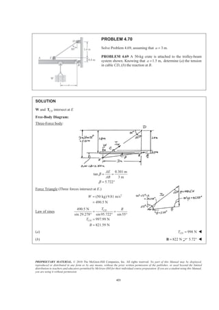
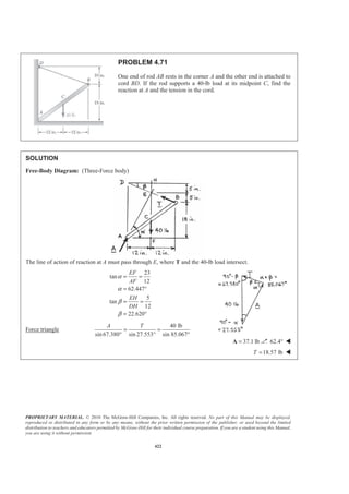

[(150 N)cos30 ](0.28 m) 0
DM AΣ = − + °
+ ° =
243.74 NA =
or 244 N=A W
0: (243.74 N) (150 N)sin30 0x xF DΣ = + ° + =
318.74 NxD = −
0: (150 N)cos30 0y yF DΣ = − ° =
129.904 NyD =
Then 2 2
2 2
( )
(318.74) (129.904)
344.19 N
x xD D D= +
= +
=
and 1
1
tan
129.904
tan
318.74
y
x
D
D
θ −
−
§ ·
= ¨ ¸
© ¹
§ ·
= ¨ ¸−© ¹
22.174= − ° or 344 N=D 22.2° W](https://image.slidesharecdn.com/mecanica-151208044028-lva1-app6892/85/Mecanica-421-320.jpg)

[(150 N)cos60 ](0.28 m) 0
DM AΣ = − + °
+ ° =
188.835 NA =
or 188.8 N=A W
0: (188.835 N) (150 N)sin 60 0x xF DΣ = + ° + =
318.74 NxD = −
0: (150 N)cos60 0y yF DΣ = − ° =
75.0 NyD =
Then 2 2
2 2
( ) ( )
(318.74) (75.0)
327.44 N
x yD D D= +
= +
=
and 1
tan
y
x
D
D
θ − § ·
= ¨ ¸
© ¹
1 75.0
tan
318.74
13.2409
− § ·
= ¨ ¸
−© ¹
= − ° or 327 N=D 13.24° W](https://image.slidesharecdn.com/mecanica-151208044028-lva1-app6892/85/Mecanica-422-320.jpg)
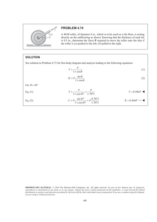
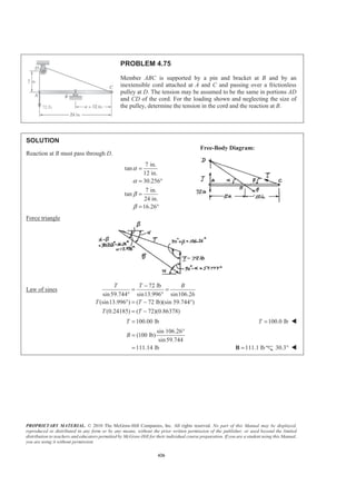
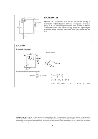
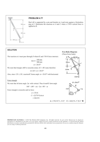
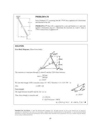
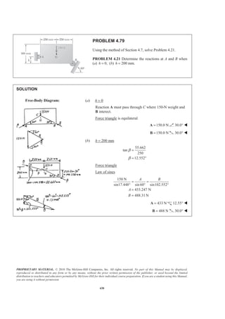
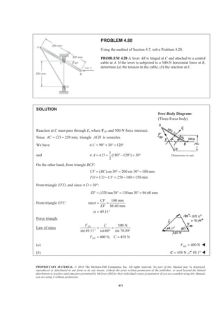
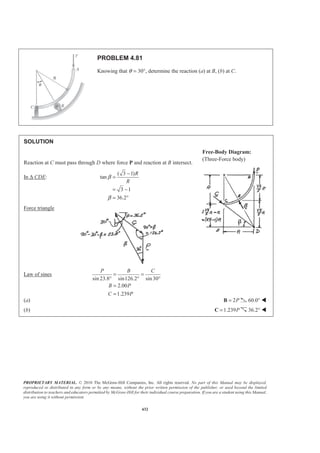
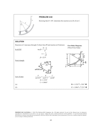
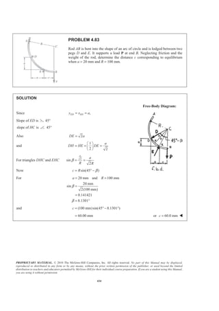
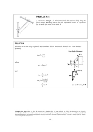
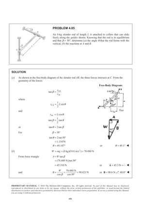
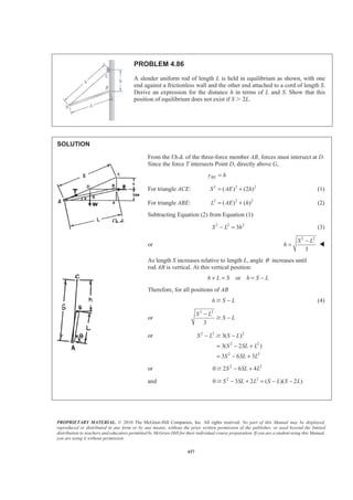
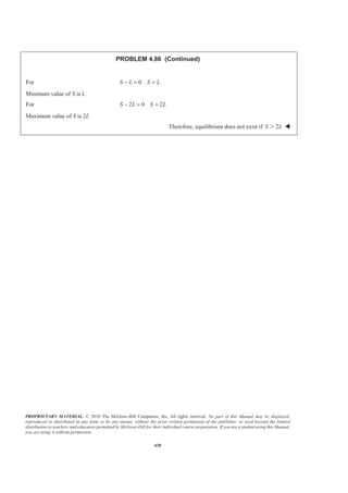
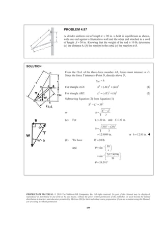
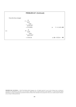
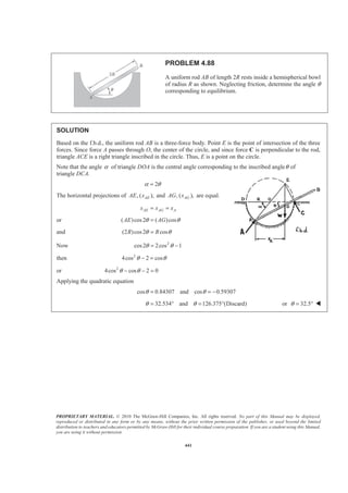
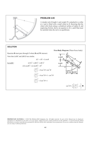
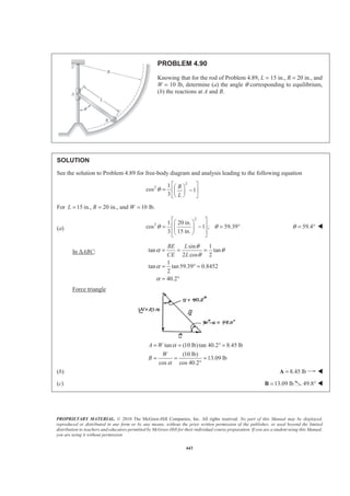
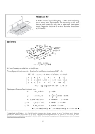
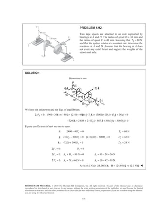
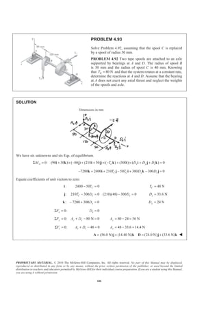
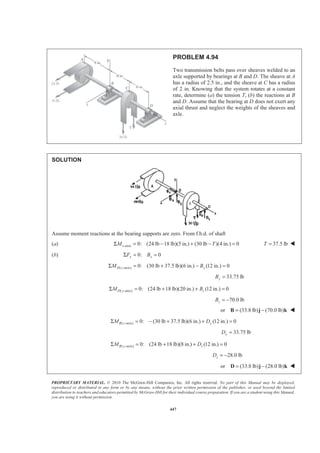
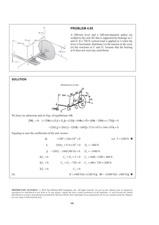
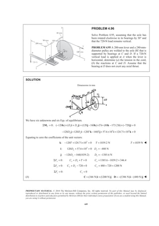
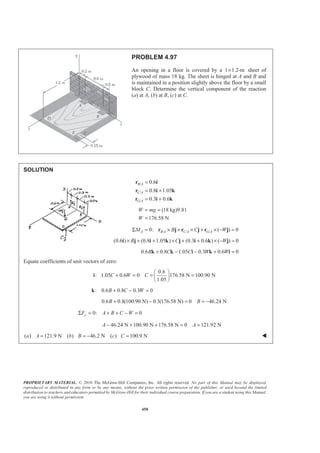
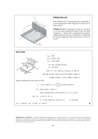
![PROPRIETARY MATERIAL. © 2010 The McGraw-Hill Companies, Inc. All rights reserved. No part of this Manual may be displayed,
reproduced or distributed in any form or by any means, without the prior written permission of the publisher, or used beyond the limited
distribution to teachers and educators permitted by McGraw-Hill for their individual course preparation. If you are a student using this Manual,
you are using it without permission.
452
PROBLEM 4.99
The rectangular plate shown weighs 80 lb and is supported by three
vertical wires. Determine the tension in each wire.
SOLUTION
Free-Body Diagram:
/ / /0: ( 80 lb) 0B A B A C B C G BT T rΣ = × + × + × − =M r j r j j
(60 in.) [(60 in.) (15 in.) ] [(30 in.) (30 in.) ] ( 80 lb) 0A CT T× + + × + + × − =k j i k j i k j
60 60 15 2400 2400 0A C CT T T− + − − + =i k i k i
Equating to zero the coefficients of the unit vectors:
:i 60 15(40) 2400 0AT − + = 30.0 lbAT = W
:k 60 2400 0CT − = 40.0 lbCT = W
0:yFΣ = 80 lb 0A B CT T T+ + − =
30 lb 40 lb 80 lb 0BT+ + − = 10.00 lbBT = W](https://image.slidesharecdn.com/mecanica-151208044028-lva1-app6892/85/Mecanica-450-320.jpg)
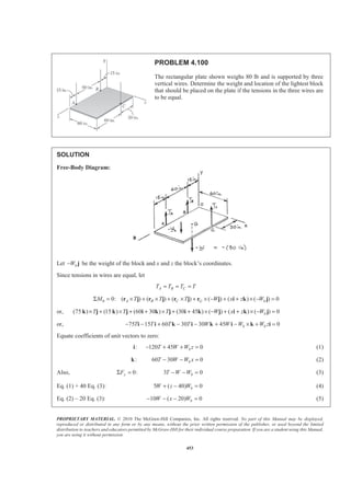
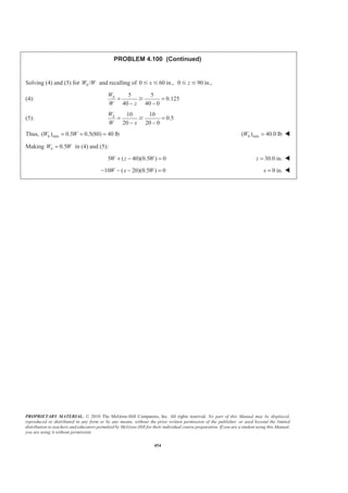
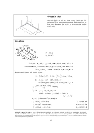
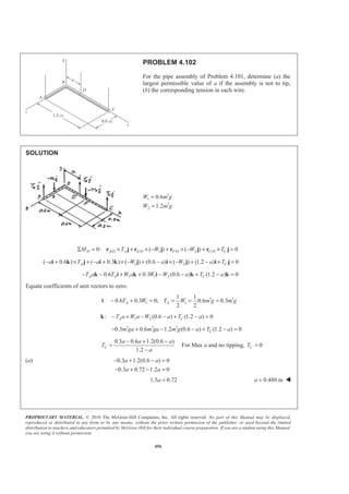
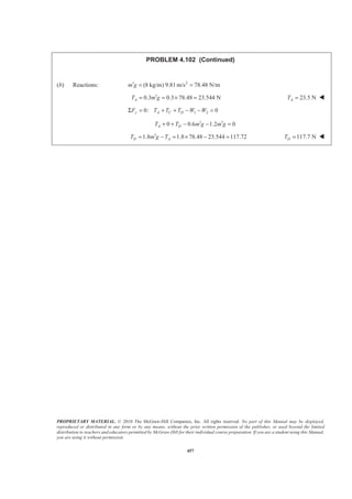
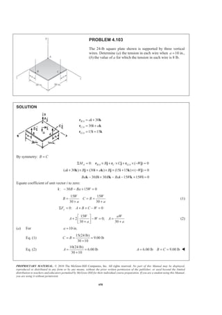
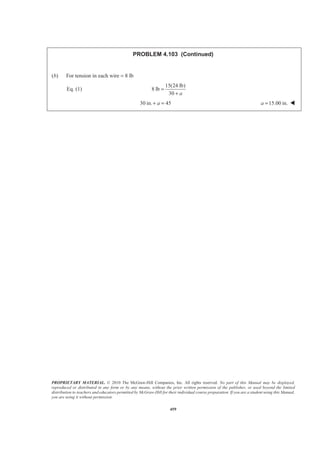
![PROPRIETARY MATERIAL. © 2010 The McGraw-Hill Companies, Inc. All rights reserved. No part of this Manual may be displayed,
reproduced or distributed in any form or by any means, without the prior written permission of the publisher, or used beyond the limited
distribution to teachers and educators permitted by McGraw-Hill for their individual course preparation. If you are a student using this Manual,
you are using it without permission.
460
PROBLEM 4.104
The table shown weighs 30 lb and has a diameter of 4 ft. It is supported by
three legs equally spaced around the edge. A vertical load P of magnitude
100 lb is applied to the top of the table at D. Determine the maximum
value of a if the table is not to tip over. Show, on a sketch, the area of the
table over which P can act without tipping the table.
SOLUTION
2 ft sin30 1ftr b r= = ° =
We shall sum moments about AB.
( ) ( ) 0b r C a b P bW+ + − − =
(1 2) ( 1)100 (1)30 0C a+ + − − =
1
[30 ( 1)100]
3
C a= − −
If table is not to tip, 0C Ն
[30 ( 1)100] 0
30 ( 1)100
a
a
− −
−
Ն
Ն
1 0.3 1.3 ft 1.300 fta a a− =Յ Յ
Only⊥ distance from P to AB matters. Same condition must be satisfied for each leg. P must be located
in shaded area for no tipping](https://image.slidesharecdn.com/mecanica-151208044028-lva1-app6892/85/Mecanica-458-320.jpg)
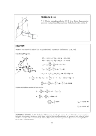

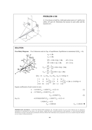
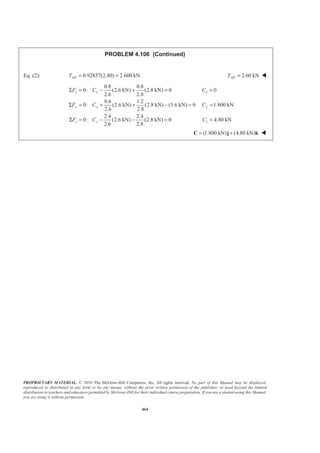
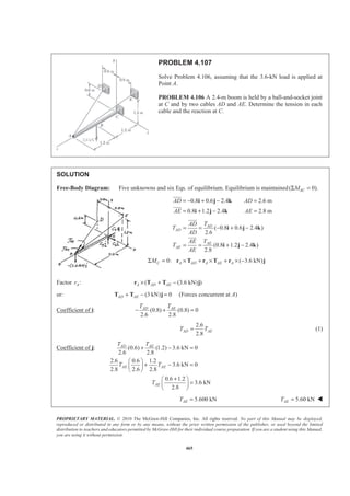
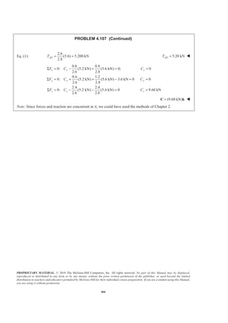
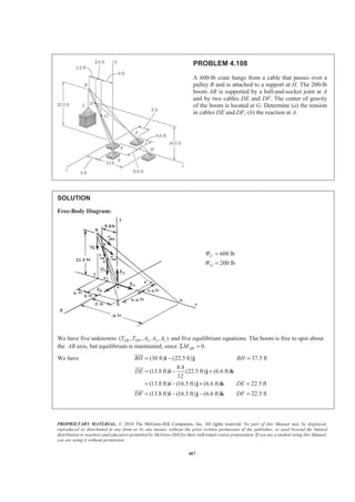
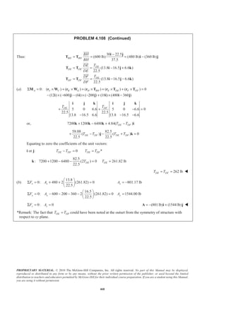
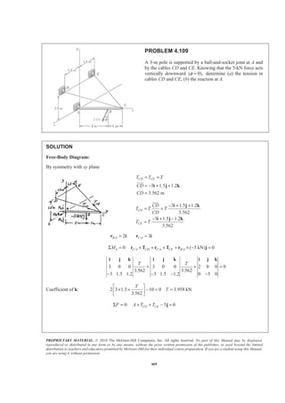
![PROPRIETARY MATERIAL. © 2010 The McGraw-Hill Companies, Inc. All rights reserved. No part of this Manual may be displayed,
reproduced or distributed in any form or by any means, without the prior written permission of the publisher, or used beyond the limited
distribution to teachers and educators permitted by McGraw-Hill for their individual course preparation. If you are a student using this Manual,
you are using it without permission.
470
PROBLEM 4.109 (Continued)
Coefficient of k: 0zA =
Coefficient of i: 2[3.958 3/3.562] 0 6.67 kNx xA A− × = =
Coefficient of j: 2[3.958 1.5/3.562] 5 0 1.667 kNy yA A+ × − = =
(a) 3.96 kNCD CET T= =
(b) (6.67 kN) (1.667 kN)= +A i j W](https://image.slidesharecdn.com/mecanica-151208044028-lva1-app6892/85/Mecanica-468-320.jpg)

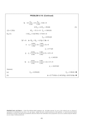
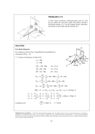
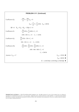
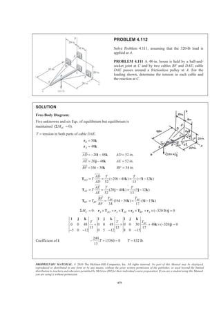
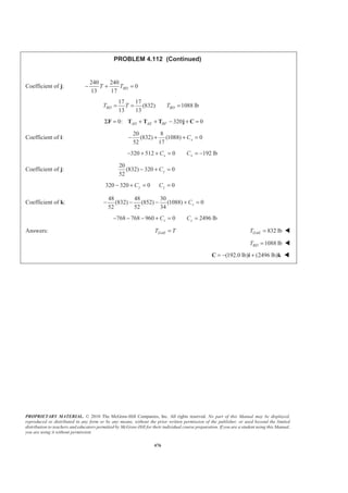
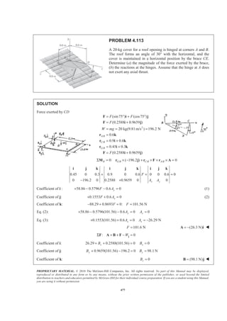
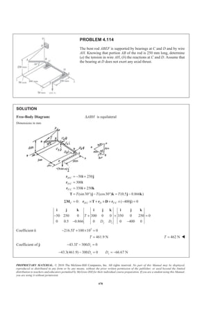
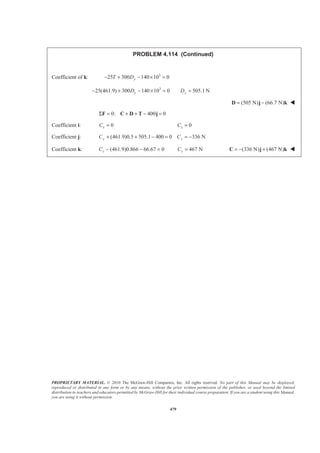
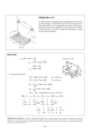
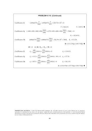

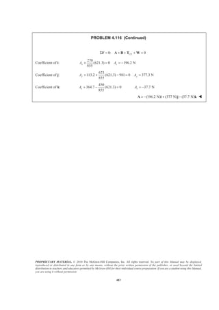
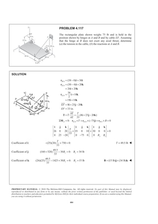
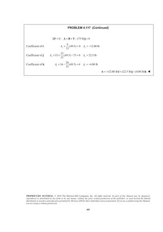
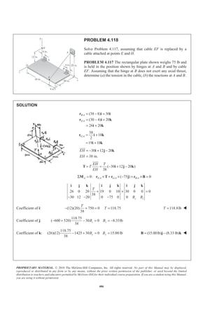
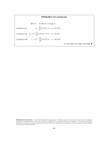
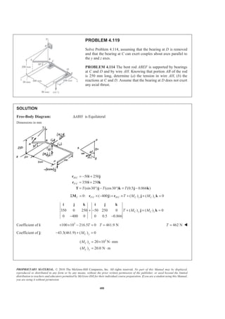
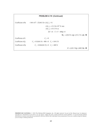
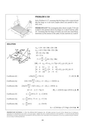
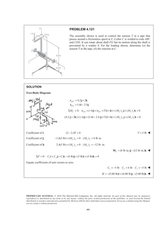
![PROPRIETARY MATERIAL. © 2010 The McGraw-Hill Companies, Inc. All rights reserved. No part of this Manual may be displayed,
reproduced or distributed in any form or by any means, without the prior written permission of the publisher, or used beyond the limited
distribution to teachers and educators permitted by McGraw-Hill for their individual course preparation. If you are a student using this Manual,
you are using it without permission.
492
PROBLEM 4.122
The assembly shown is welded to collar A that fits on the vertical
pin shown. The pin can exert couples about the x and z axes but
does not prevent motion about or along the y axis. For the loading
shown, determine the tension in each cable and the reaction at A.
SOLUTION
Free-Body Diagram:
First note
2 2
2 2
(0.08 m) (0.06 m)
(0.08) (0.06) m
( 0.8 0.6 )
(0.12 m) (0.09 m)
(0.12) (0.09) m
(0.8 0.6 )
− +
= =
+
= − +
−
= =
+
= −
CF CF CF CF
CF
DE DE DE DE
DE
T T
T
T T
T
i j
T Ȝ
i j
j k
T Ȝ
j k
(a) From f.b.d. of assembly
0: 0.6 0.8 480 N 0Σ = + − =y CF DEF T T
or 0.6 0.8 480 NCF DET T+ = (1)
0: (0.8 )(0.135 m) (0.6 )(0.08 m) 0Σ = − + =y CF DEM T T
or 2.25DE CFT T= (2)
Substituting Equation (2) into Equation (1)
0.6 0.8[(2.25) ] 480 NCF CFT T+ =
200.00 NCFT =
or 200 NCFT = W
and from Equation (2) 2.25(200.00 N) 450.00DET = =
or 450 NDET = W](https://image.slidesharecdn.com/mecanica-151208044028-lva1-app6892/85/Mecanica-490-320.jpg)

[(450 N)(0.8)](0.09 m) 0
Σ = + −
− =
xx AM M
16.2000 N mxAM = − ⋅
0: (480 N)(0.08 m) [(200.00 N)(0.6)](0.08 m)
[(450 N)(0.8)](0.08 m) 0
Σ = − +
+ =
zz AM M
0zAM =
or (16.20 N m)A = − ⋅M i W](https://image.slidesharecdn.com/mecanica-151208044028-lva1-app6892/85/Mecanica-491-320.jpg)
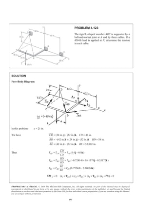
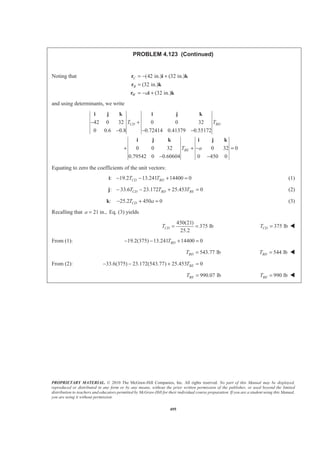
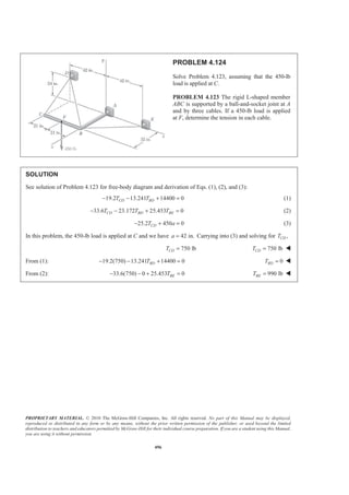
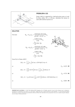
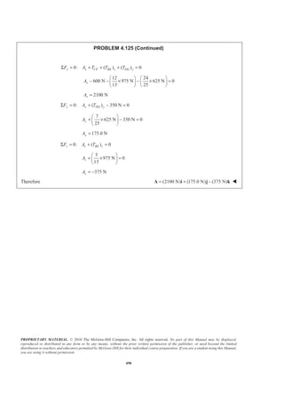
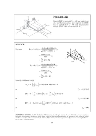
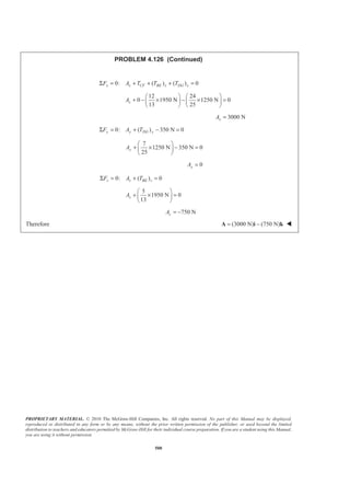
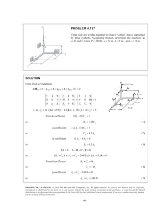
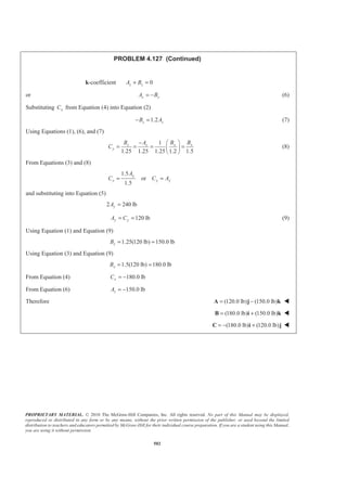
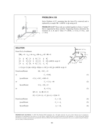
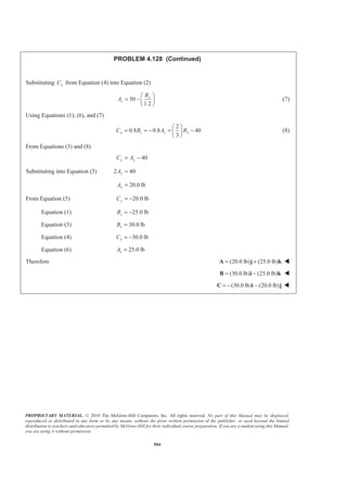
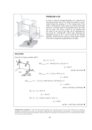
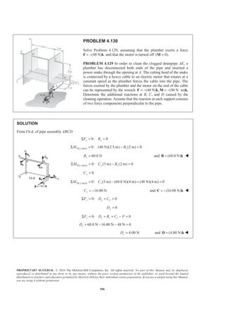
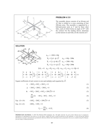
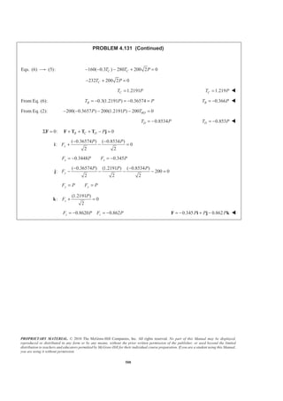
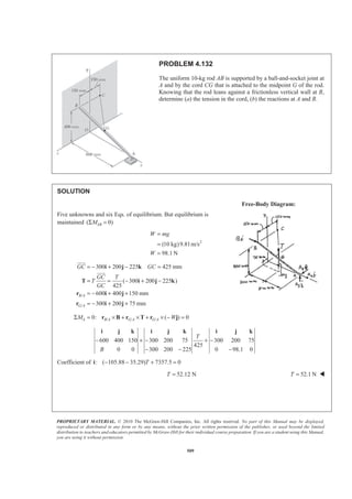
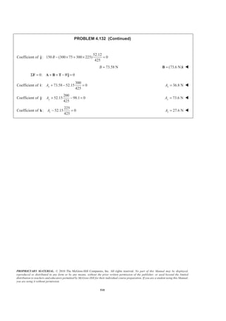
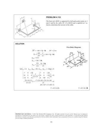
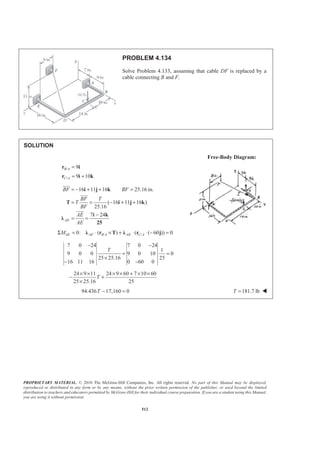
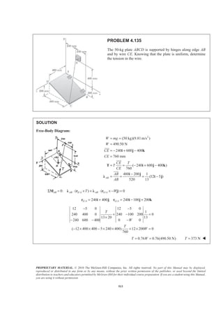
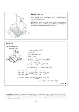
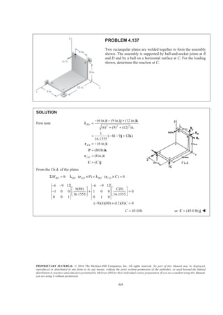
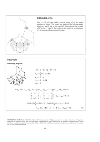
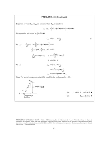
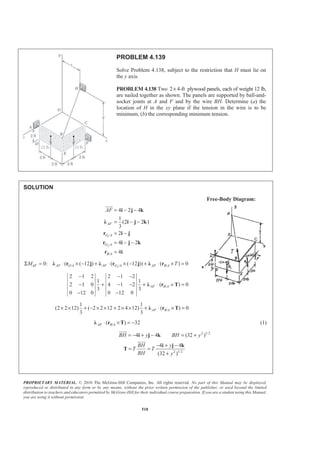
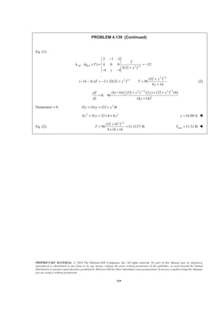
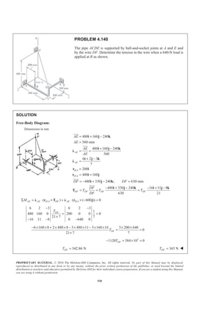
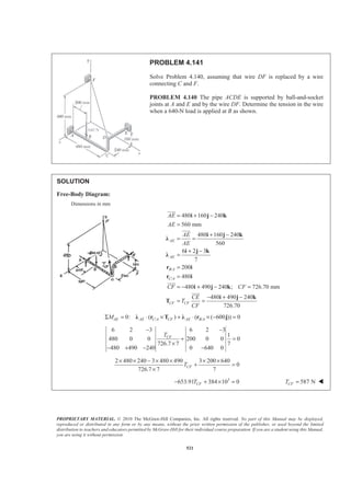
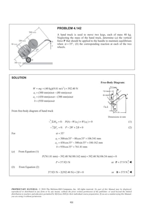
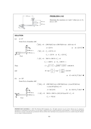
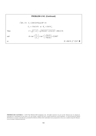
![PROPRIETARY MATERIAL. © 2010 The McGraw-Hill Companies, Inc. All rights reserved. No part of this Manual may be displayed,
reproduced or distributed in any form or by any means, without the prior written permission of the publisher, or used beyond the limited
distribution to teachers and educators permitted by McGraw-Hill for their individual course preparation. If you are a student using this Manual,
you are using it without permission.
525
PROBLEM 4.144
A lever AB is hinged at C and attached to a control cable at A. If the
lever is subjected to a 75-lb vertical force at B, determine (a) the
tension in the cable, (b) the reaction at C.
SOLUTION
Free-Body Diagram:
Geometry:
(10 in.)cos20 9.3969 in.
(10 in.)sin 20 3.4202 in.
AC
AC
x
y
= ° =
= ° =
12 in. 3.4202 in. 8.5798 in.DAyŸ = − =
1 1 8.5798
tan tan 42.397
9.3969
DA
AC
y
x
α − −§ · § ·
= = = °¨ ¸ ¨ ¸
© ¹© ¹
90 20 42.397 27.603β = ° − ° − ° = °
Equilibrium for lever:
(a) 0: cos27.603 (10 in.) (75 lb)[(15 in.)cos 20°] 0C ADM TΣ = ° − =
119.293 lbADT = 119.3 lbADT = W
(b) 0: (119.293 lb)cos42.397 0x xF CΣ = + ° =
88.097 lbxC = −
0: 75 lb lb)sin 42.397 0y yF CΣ = − − (119.293 ° =
155.435yC =
Thus: 2 2 2 2
( 88.097) (155.435) 178.665 lbx yC C C= + = − + =
and 1 1 155.435
tan tan 60.456
88.097
y
x
C
C
θ − −
= = = ° 178.7 lb=C 60.5° W](https://image.slidesharecdn.com/mecanica-151208044028-lva1-app6892/85/Mecanica-523-320.jpg)
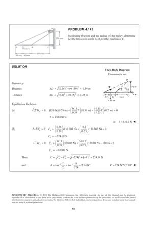
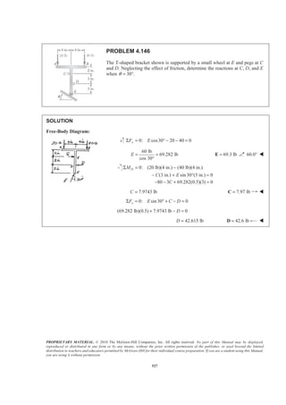
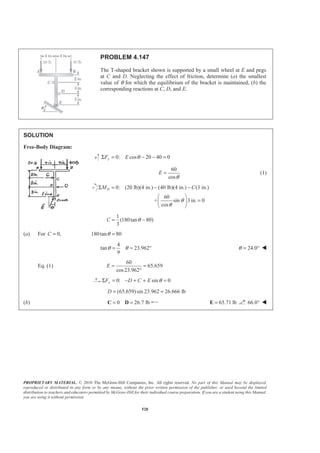
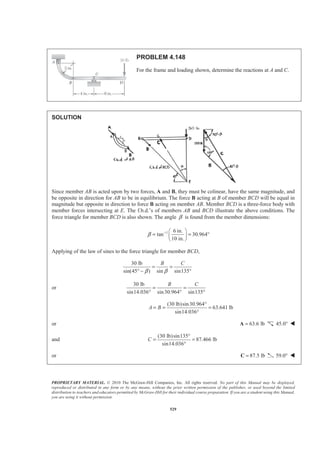
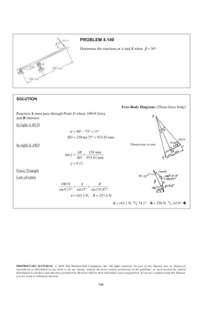
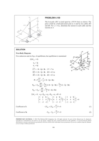
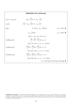
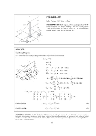

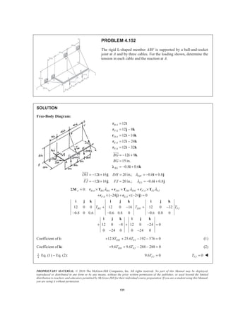
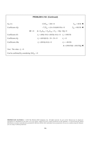
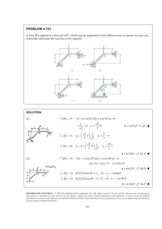

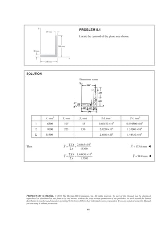
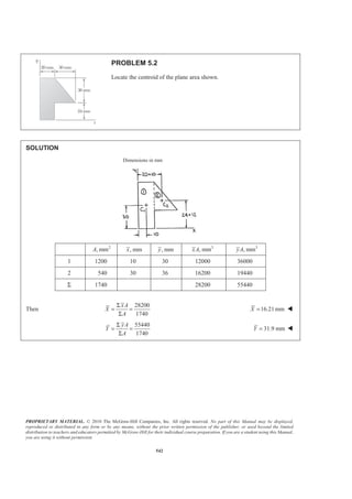
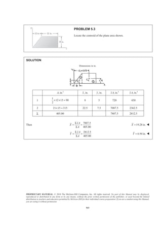
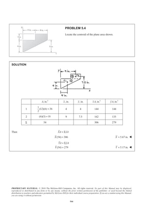
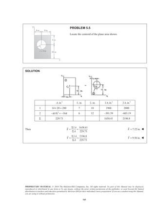
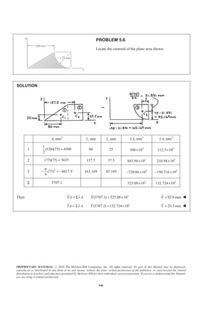
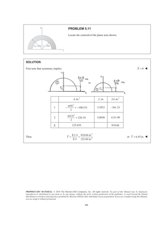

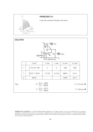
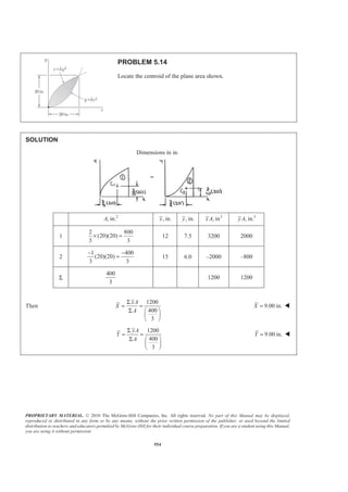
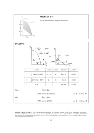
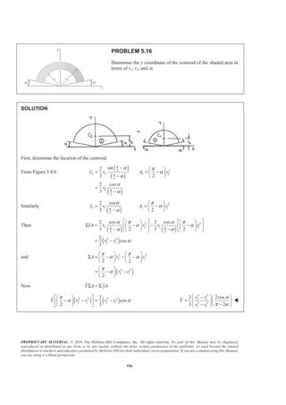
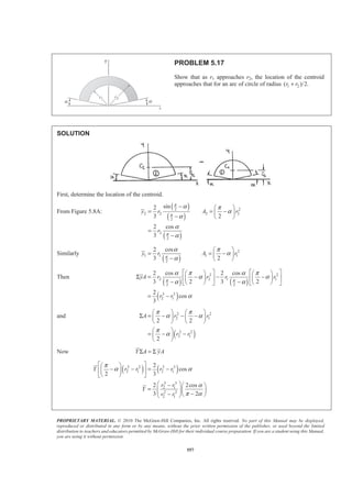
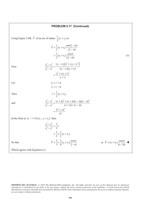
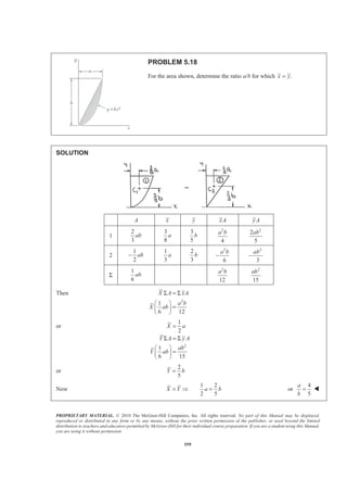
![PROPRIETARY MATERIAL. © 2010 The McGraw-Hill Companies, Inc. All rights reserved. No part of this Manual may be displayed,
reproduced or distributed in any form or by any means, without the prior written permission of the publisher, or used beyond the limited
distribution to teachers and educators permitted by McGraw-Hill for their individual course preparation. If you are a student using this Manual,
you are using it without permission.
560
PROBLEM 5.19
For the semiannular area of Problem 5.11, determine the ratio r2/r1 so
that 13 /4.y r=
SOLUTION
A Y YA
1 2
1
2
r
π
− 14
3
r
π
3
1
2
3
r−
2 2
2
2
r
π 24
3
r
π
3
2
2
3
r
Σ ( )2 2
2 1
2
r r
π
− ( )3 3
2 1
2
3
r r−
Then Y A yAΣ = Σ
or ( ) ( )2 2 3 3
1 2 1 2 1
2 3
2 2
1 1
3 2
4 2 3
9
1 1
16
r r r r r
r r
r r
π
π
× − = −
ª º§ · § ·
« »− = −¨ ¸ ¨ ¸
« »© ¹ © ¹¬ ¼
Let 2
1
29
[( 1)( 1)] ( 1)( 1)
16
π
=
+ − = − + +
r
p
r
p p p p p
or 2
16 (16 9 ) (16 9 ) 0π π+ − + − =p p](https://image.slidesharecdn.com/mecanica-151208044028-lva1-app6892/85/Mecanica-558-320.jpg)
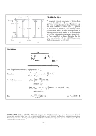

![PROPRIETARY MATERIAL. © 2010 The McGraw-Hill Companies, Inc. All rights reserved. No part of this Manual may be displayed,
reproduced or distributed in any form or by any means, without the prior written permission of the publisher, or used beyond the limited
distribution to teachers and educators permitted by McGraw-Hill for their individual course preparation. If you are a student using this Manual,
you are using it without permission.
564
PROBLEM 5.22
The horizontal x axis is drawn through the centroid C of the area shown,
and it divides the area into two component areas 1A and 2.A Determine
the first moment of each component area with respect to the x axis, and
explain the results obtained.
SOLUTION
First determine the location of the centroid C. We have
2
, in.A , in.y′ 3
, in.y A′
I
1
2 2 1.5 3
2
§ ·
× × =¨ ¸
© ¹
0.5 1.5
II 1.5 5.5 8.25× = 2.75 22.6875
III 4.5 2 9× = 6.5 58.5
Σ 20.25 82.6875
Then
(20.25) 82.6875
Y A y A
Y
′ ′Σ = Σ
′ =
or 4.0833 in.Y′ =
Now 1xQ y A= Σ
Then 2
1
1
( ) (5.5 4.0833)in. [(1.5)(5.5 4.0833)]in.
2
xQ
ª º
= − −« »
¬ ¼
2
[(6.5 4.0833)in.][(4.5)(2)]in.+ − or 3
1( ) 23.3 in.xQ = W
and 2
2
1
( ) (4.0833 in.) [(1.5)(4.0833)]in.
2
xQ
ª º
= −« »
¬ ¼
21
[(4.0833 0.5)in.] 2 2 1.5 in.
2
ª º§ ·
− − × × ×« »¨ ¸
© ¹¬ ¼
or 3
2( ) 23.3 in.xQ = − W](https://image.slidesharecdn.com/mecanica-151208044028-lva1-app6892/85/Mecanica-562-320.jpg)
![PROPRIETARY MATERIAL. © 2010 The McGraw-Hill Companies, Inc. All rights reserved. No part of this Manual may be displayed,
reproduced or distributed in any form or by any means, without the prior written permission of the publisher, or used beyond the limited
distribution to teachers and educators permitted by McGraw-Hill for their individual course preparation. If you are a student using this Manual,
you are using it without permission.
566
PROBLEM 5.23
The first moment of the shaded area with respect to the x axis is denoted by Qx.
(a) Express Qx in terms of b, c, and the distance y from the base of the shaded
area to the x axis. (b) For what value of y is xO maximum, and what is that
maximum value?
SOLUTION
Shaded area:
( )
1
( )[ ( )]
2
x
A b c y
Q yA
c y b c y
= −
=
= + −
(a) 2 21
( )
2
xQ b c y= − W
(b) For max :Q
1
0 or ( 2 ) 0
2
dQ
b y
dy
= − = 0y = W
For 0:y = 21
( )
2
xQ bc= 21
( )
2
xQ bc= W](https://image.slidesharecdn.com/mecanica-151208044028-lva1-app6892/85/Mecanica-564-320.jpg)
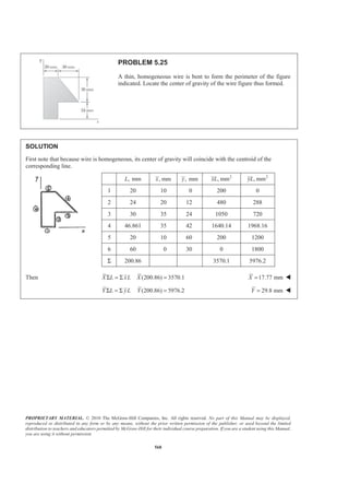
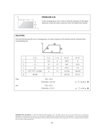
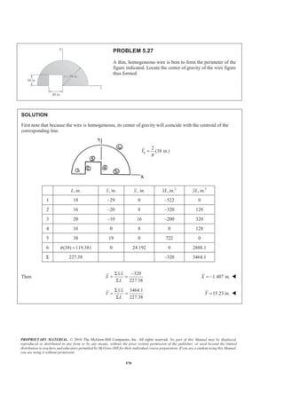
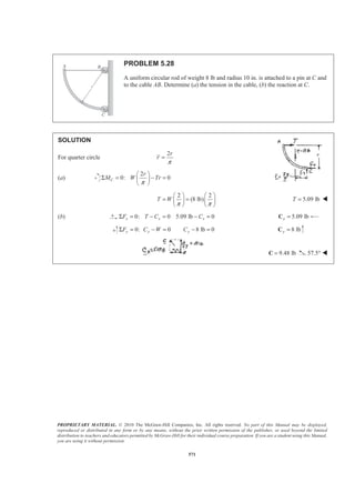
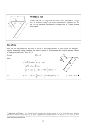
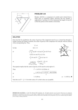
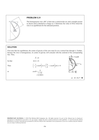
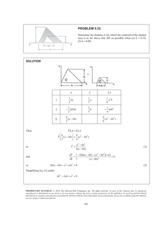
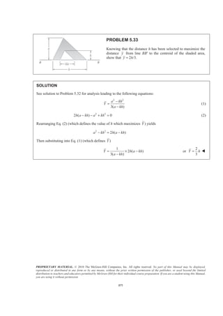
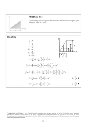
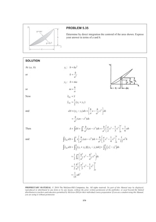
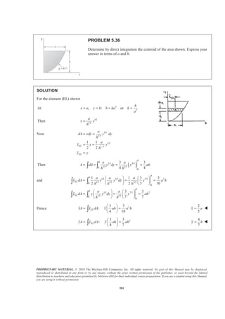
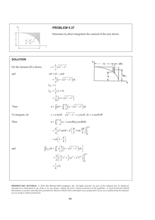
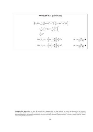
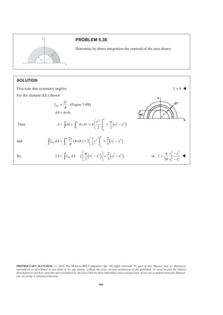
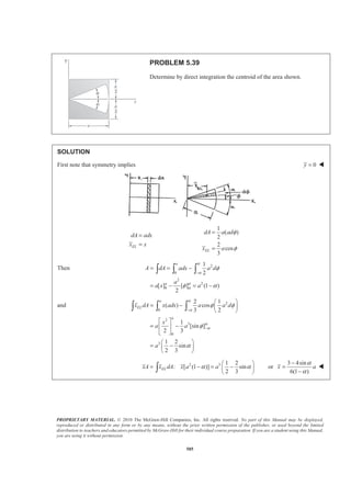
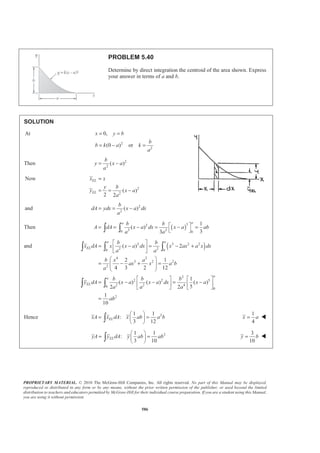
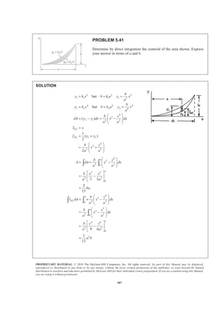
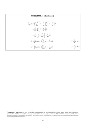
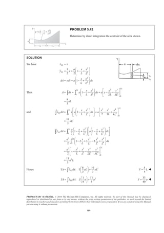
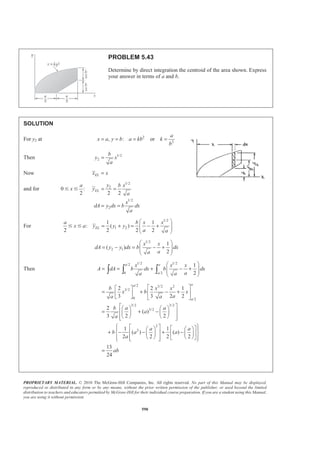
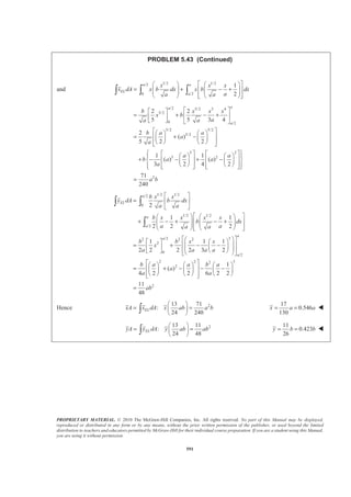
![PROPRIETARY MATERIAL. © 2010 The McGraw-Hill Companies, Inc. All rights reserved. No part of this Manual may be displayed,
reproduced or distributed in any form or by any means, without the prior written permission of the publisher, or used beyond the limited
distribution to teachers and educators permitted by McGraw-Hill for their individual course preparation. If you are a student using this Manual,
you are using it without permission.
579
PROBLEM 5.35
Determine by direct integration the centroid of the area shown. Express
your answer in terms of a and h.
SOLUTION
At ( , )a h 2
1 :y h ka=
or 2
h
k
a
=
2 :y h ma=
or
h
m
a
=
Now
1 2
1
( )
2
EL
EL
x x
y y y
=
= +
and 2
2 1 2
2
2
( )
( )
h h
dA y y dx x x dx
a a
h
ax x dx
a
ª º
= − = −« »
¬ ¼
= −
Then 2 2 3
2 20
0
1 1
( )
2 3 6
a
a h h a
A dA ax x dx x x ah
a a
ª º
= = − = − =« »
¬ ¼³ ³
and
( )
2 3 4 2
2 20
0
2 2
1 2 2 1 2 1
1 1
( )
3 4 12
1 1
( )[( ) ]
2 2
a
a
EL
EL
h h a
x dA x ax x dx x x a h
a a
y dA y y y y dx y y dx
ª ª º
= − = − =« « »
¬ ¬ ¼
= + − = −
³ ³
³ ³ ³
2 2
2 4
2 40
2 2
3 5
4
0
2
1
2
1 1
2 3 5
1
15
a
a
h h
x x dx
a a
h a
x x
a
ah
§ ·
= −¨ ¸¨ ¸
© ¹
ª º
= −« »
¬ ¼
=
³](https://image.slidesharecdn.com/mecanica-151208044028-lva1-app6892/85/Mecanica-590-320.jpg)
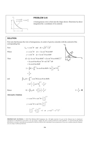
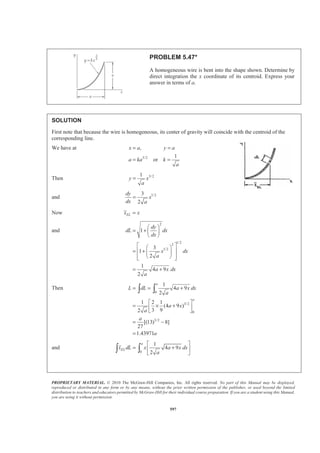
![PROPRIETARY MATERIAL. © 2010 The McGraw-Hill Companies, Inc. All rights reserved. No part of this Manual may be displayed,
reproduced or distributed in any form or by any means, without the prior written permission of the publisher, or used beyond the limited
distribution to teachers and educators permitted by McGraw-Hill for their individual course preparation. If you are a student using this Manual,
you are using it without permission.
585
PROBLEM 5.39
Determine by direct integration the centroid of the area shown.
SOLUTION
First note that symmetry implies 0y = W
EL
dA adx
x x
=
=
1
( )
2
2
cos
3
EL
dA a ad
x a
φ
φ
=
=
Then 2
0
2
2
0
1
2
[ ] [ ] (1 )
2
α
α
α
α
φ
φ α
−
= = −
= − = −
³ ³ ³
a
a
A dA adx a d
a
a x a
and 2
0
2
3
0
3
2 1
( ) cos
3 2
1
[sin ]
2 3
1 2
sin
2 3
α
α
α
α
φ φ
φ
α
−
−
§ ·
= − ¨ ¸
© ¹
ª º
= −« »
¬ ¼
§ ·
= −¨ ¸
© ¹
³ ³ ³
a
EL
a
x dA x adx a a d
x
a a
a
2 3 1 2
: [ (1 )] sin
2 3
ELxA x dA x a aα α
§ ·
= − = −¨ ¸
© ¹³ or
3 4sin
6(1 )
x a
α
α
−
=
−
W](https://image.slidesharecdn.com/mecanica-151208044028-lva1-app6892/85/Mecanica-596-320.jpg)
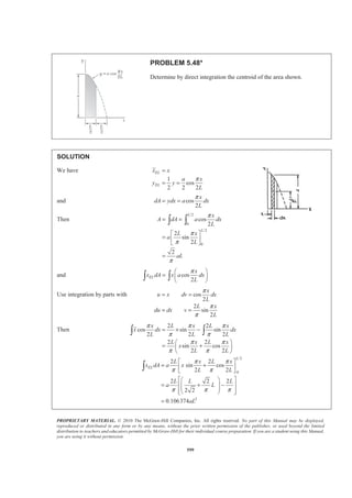
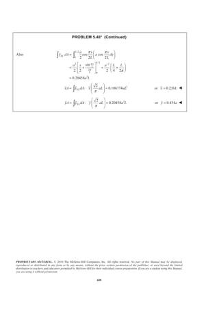
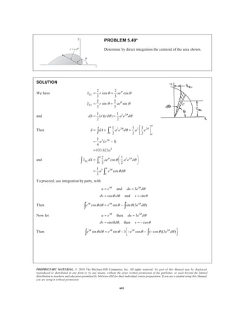
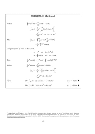
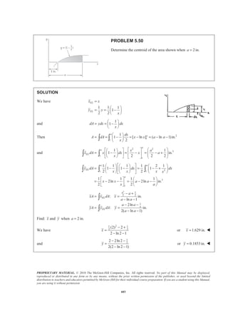
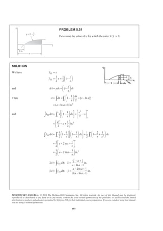
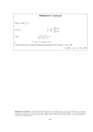
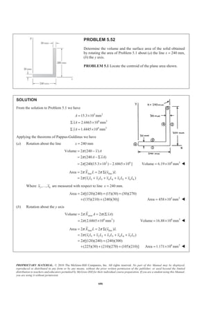
![PROPRIETARY MATERIAL. © 2010 The McGraw-Hill Companies, Inc. All rights reserved. No part of this Manual may be displayed,
reproduced or distributed in any form or by any means, without the prior written permission of the publisher, or used beyond the limited
distribution to teachers and educators permitted by McGraw-Hill for their individual course preparation. If you are a student using this Manual,
you are using it without permission.
594
PROBLEM 5.45
A homogeneous wire is bent into the shape shown. Determine by direct
integration the x coordinate of its centroid.
SOLUTION
First note that because the wire is homogeneous, its center of gravity coincides with the centroid of the
corresponding line
Now 3 2 2
cos andELx a dL dx dyθ= = +
Where 3 2
3 2
cos : 3 cos sin
sin : 3 sin cos
x a dx a d
y a dy a d
θ θ θ θ
θ θ θ θ
= = −
= =
Then 2 2 2 2 1/2
2 2 1/2
/2
/2
2
0
0
[( 3 cos sin ) (3 sin cos ) ]
3 cos sin (cos sin )
3 cos sin
1
3 cos sin 3 sin
2
3
2
dL a d a d
a d
a d
L dL a d a
a
π
π
θ θ θ θ θ θ
θ θ θ θ θ
θ θ θ
θ θ θ θ
= − +
= +
=
ª º
= = = « »
¬ ¼
=
³ ³
and
/2
3
0
/2
2 5 2
0
cos (3 cos sin )
1 3
3 cos
5 5
ELx dL a a d
a a
π
π
θ θ θ θ
θ
=
ª º
= − =« »
¬ ¼
³ ³
Hence 23 3
:
2 5
ELxL x dL x a a
§ ·
= =¨ ¸
© ¹³
2
5
x a= W
Alternative Solution
2/3
3 2
2/3
3 2
cos cos
sin sin
x
x a
a
y
y a
a
θ θ
θ θ
§ ·
= Ÿ = ¨ ¸
© ¹
§ ·
= Ÿ = ¨ ¸
© ¹
2/3 2/3
2/3 2/3 3/2
1 or ( )
x y
y a x
a a
§ · § ·
+ = = −¨ ¸ ¨ ¸
© ¹ © ¹](https://image.slidesharecdn.com/mecanica-151208044028-lva1-app6892/85/Mecanica-605-320.jpg)
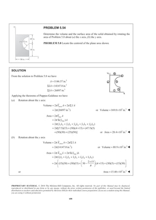
![PROPRIETARY MATERIAL. © 2010 The McGraw-Hill Companies, Inc. All rights reserved. No part of this Manual may be displayed,
reproduced or distributed in any form or by any means, without the prior written permission of the publisher, or used beyond the limited
distribution to teachers and educators permitted by McGraw-Hill for their individual course preparation. If you are a student using this Manual,
you are using it without permission.
596
PROBLEM 5.46
A homogeneous wire is bent into the shape shown. Determine by direct
integration the x coordinate of its centroid.
SOLUTION
First note that because the wire is homogeneous, its center of gravity coincides with the centroid of the
corresponding line
Now cos andELx r dL rdθ θ= =
Then
7 /4
7 /4
/4
/4
3
[ ]
2
L dL rd r r
π
π
π
π
θ θ π= = = =³ ³
and
7 /4
/4
2 7 /4
/4
2
2
cos ( )
[sin ]
1 1
2 2
2
ELx dL r rd
r
r
r
π
π
π
π
θ θ
θ
=
=
§ ·
= − −¨ ¸
© ¹
= −
³ ³
Thus 23
: 2
2
xL xdL x r rπ
§ ·
= = −¨ ¸
© ¹³
2 2
3
x r
π
= − W](https://image.slidesharecdn.com/mecanica-151208044028-lva1-app6892/85/Mecanica-607-320.jpg)
![PROPRIETARY MATERIAL. © 2010 The McGraw-Hill Companies, Inc. All rights reserved. No part of this Manual may be displayed,
reproduced or distributed in any form or by any means, without the prior written permission of the publisher, or used beyond the limited
distribution to teachers and educators permitted by McGraw-Hill for their individual course preparation. If you are a student using this Manual,
you are using it without permission.
597
PROBLEM 5.47*
A homogeneous wire is bent into the shape shown. Determine by
direct integration the x coordinate of its centroid. Express your
answer in terms of a.
SOLUTION
First note that because the wire is homogeneous, its center of gravity will coincide with the centroid of the
corresponding line.
We have at
3/2
,
1
or
x a y a
a ka k
a
= =
= =
Then 3/21
y x
a
=
and 1/23
2
dy
x
dx a
=
Now ELx x=
and
2
1/22
1/2
1
3
1
2
1
4 9
2
dy
dL dx
dx
x dx
a
a x dx
a
§ ·
= + ¨ ¸
© ¹
ª º§ ·
« »= + ¨ ¸
« »© ¹¬ ¼
= +
Then
0
3/2
0
3/2
1
4 9
2
1 2 1
(4 9 )
3 92
[(13) 8]
27
1.43971
a
a
L dL a x dx
a
a x
a
a
a
= = +
ª º
= × +« »
¬ ¼
= −
=
³ ³
and
0
1
4 9
2
a
ELx dL x a x dx
a
ª º
= +« »
¬ ¼
³ ³](https://image.slidesharecdn.com/mecanica-151208044028-lva1-app6892/85/Mecanica-608-320.jpg)
![PROPRIETARY MATERIAL. © 2010 The McGraw-Hill Companies, Inc. All rights reserved. No part of this Manual may be displayed,
reproduced or distributed in any form or by any means, without the prior written permission of the publisher, or used beyond the limited
distribution to teachers and educators permitted by McGraw-Hill for their individual course preparation. If you are a student using this Manual,
you are using it without permission.
598
PROBLEM 5.47* (Continued)
Use integration by parts with
3/2
4 9
2
(4 9 )
27
u x dv a x dx
du dx v a x
= = +
= = +
Then 3/2 3/2
0
0
3/2
2 5/2
0
2
3/2 5/2
2
1 2 2
(4 9 ) (4 9 )
27 272
(13) 1 2
(4 9 )
27 4527
2
(13) [(13) 32]
27 45
0.78566
a
a
EL
a
x dL x a x a x dx
a
a a x
a
a
a
½° °ª º
= × + − +® ¾« »
¬ ¼° °¯ ¿
ª º
= − +« »
¬ ¼
½
= − −® ¾
¯ ¿
=
³ ³
2
: (1.43971 ) 0.78566ELxL x dL x a a= =³ or 0.546x a= W](https://image.slidesharecdn.com/mecanica-151208044028-lva1-app6892/85/Mecanica-609-320.jpg)
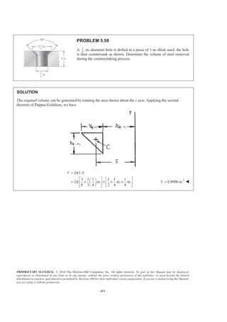
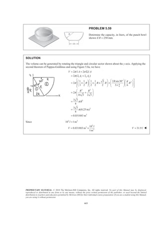
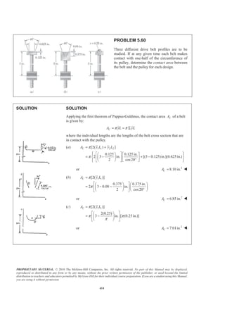
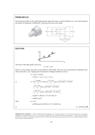
![PROPRIETARY MATERIAL. © 2010 The McGraw-Hill Companies, Inc. All rights reserved. No part of this Manual may be displayed,
reproduced or distributed in any form or by any means, without the prior written permission of the publisher, or used beyond the limited
distribution to teachers and educators permitted by McGraw-Hill for their individual course preparation. If you are a student using this Manual,
you are using it without permission.
603
PROBLEM 5.50
Determine the centroid of the area shown when 2a = in.
SOLUTION
We have
1 1 1
1
2 2
EL
EL
x x
y y
x
=
§ ·
= = −¨ ¸
© ¹
and
1
1dA ydx dx
x
§ ·
= = −¨ ¸
© ¹
Then 2
1
1
1
1 [ ln ] ( ln 1)in.
2
a
adx
A dA x x a a
x
§ ·
= = − = − = − −¨ ¸
© ¹³ ³
and
2 2
3
1
1
1 1
1 in.
2 2 2
ª º § ·ª º§ ·
= − = − = − +¨ ¸« »« »¨ ¸ ¨ ¸© ¹¬ ¼ ¬ ¼ © ¹
³ ³
a
a
EL
x a
x dA x dx x a
x
21 1
3
1
1 1 1 1 2 1
1 1 1
2 2
1 1 1 1
2ln 2ln in.
2 2
a a
EL
a
y dA dx dx
x x x x
x x a a
x a
ª º§ · § · § ·
= − − = − +« »¨ ¸ ¨ ¸ ¨ ¸
© ¹ © ¹ © ¹¬ ¼
ª º § ·
= − − = − −¨ ¸« »
¬ ¼ © ¹
³ ³ ³
2
1
2 2
1
: in.
ln 1
2ln
: in.
2( ln 1)
a
EL
a
EL
a
xA x dA x
a a
a a
yA y dA y
a a
− +
= =
− −
− −
= =
− −
³
³
Find: x and y when 2 in.=a
We have
21 1
2 2
(2) 2
2 ln 2 1
x
− +
=
− −
or 1.629 in.x = W
and
1
2
2 2ln 2
2(2 ln 2 1)
y
− −
=
− −
or 0.1853 in.y = W](https://image.slidesharecdn.com/mecanica-151208044028-lva1-app6892/85/Mecanica-614-320.jpg)
![PROPRIETARY MATERIAL. © 2010 The McGraw-Hill Companies, Inc. All rights reserved. No part of this Manual may be displayed,
reproduced or distributed in any form or by any means, without the prior written permission of the publisher, or used beyond the limited
distribution to teachers and educators permitted by McGraw-Hill for their individual course preparation. If you are a student using this Manual,
you are using it without permission.
604
PROBLEM 5.51
Determine the value of a for which the ratio /x y is 9.
SOLUTION
We have
1 1 1
1
2 2
EL
EL
x x
y y
x
=
§ ·
= = −¨ ¸
© ¹
and
1
1dA ydx dx
x
§ ·
= = −¨ ¸
© ¹
Then 1
1
2
1
1 [ ln ]
2
( ln 1)in.
a
adx
A dA x x
x
a a
§ ·
= = − = −¨ ¸
© ¹
= − −
³ ³
and
2
1
1
2
3
1
1
2
1
in.
2 2
ª ºª º§ ·
= − = −« »« »¨ ¸
© ¹¬ ¼ ¬ ¼
§ ·
= − +¨ ¸¨ ¸
© ¹
³ ³
a
a
EL
x
x dA x dx x
x
a
a
21 1
1
3
1 1 1 1 2 1
1 1 1
2 2
1 1
2ln
2
1 1
2ln in.
2
a a
EL
a
y dA dx dx
x x x x
x x
x
a a
a
ª º§ · § · § ·
= − − = − +« »¨ ¸ ¨ ¸ ¨ ¸
© ¹ © ¹ © ¹¬ ¼
ª º
= − −« »
¬ ¼
§ ·
= − −¨ ¸
© ¹
³ ³ ³
2
1
2 2
1
: in.
ln 1
2ln
: in.
2( ln 1)
a
EL
a
EL
a
xA x dA x
a a
a a
yA y dA y
a a
− +
= =
− −
− −
= =
− −
³
³](https://image.slidesharecdn.com/mecanica-151208044028-lva1-app6892/85/Mecanica-615-320.jpg)
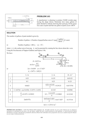
![PROPRIETARY MATERIAL. © 2010 The McGraw-Hill Companies, Inc. All rights reserved. No part of this Manual may be displayed,
reproduced or distributed in any form or by any means, without the prior written permission of the publisher, or used beyond the limited
distribution to teachers and educators permitted by McGraw-Hill for their individual course preparation. If you are a student using this Manual,
you are using it without permission.
606
PROBLEM 5.52
Determine the volume and the surface area of the solid obtained
by rotating the area of Problem 5.1 about (a) the line x = 240 mm,
(b) the y axis.
PROBLEM 5.1 Locate the centroid of the plane area shown.
SOLUTION
From the solution to Problem 5.1 we have
3 2
6 3
6 3
15.3 10 mm
2.6865 10 mm
1.4445 10 mm
A
xA
yA
= ×
Σ = ×
Σ = ×
Applying the theorems of Pappus-Guldinus we have
(a) Rotation about the line 240 mmx =
3 6
Volume 2 (240 )
2 (240 )
2 [240(15.3 10 ) 2.6865 10 ]
x A
A xA
π
π
π
= −
= − Σ
= × − × 6 3
Volume 6.19 10 mm= × W
line line
1 1 3 3 4 4 5 5 6 6
Area 2 2 ( )
2 ( )
X L x L
x L x L x L x L x L
π π
π
= = Σ
= + + + +
Where 1 6, ,x x! are measured with respect to line 240 mm.x =
Area 2 [(120)(240) (15)(30) (30)(270)
(135)(210) (240)(30)]
π= + +
+ + 3 2
Area 458 10 mm= × W
(b) Rotation about the y axis
area
6 3
Volume 2 2 ( )
2 (2.6865 10 mm )
X A xAπ π
π
= = Σ
= × 6 3
Volume 16.88 10 mm= × W
line line
1 1 2 2 3 3 4 4 5 5
Area 2 2 ( )
2 ( )
2 [(120)(240) (240)(300)
(225)(30) (210)(270) (105)(210)]
X L x L
x L x L x L x L x L
π π
π
π
= = Σ
= + + + +
= +
+ + + 6 2
Area 1.171 10 mm= × W](https://image.slidesharecdn.com/mecanica-151208044028-lva1-app6892/85/Mecanica-617-320.jpg)
![PROPRIETARY MATERIAL. © 2010 The McGraw-Hill Companies, Inc. All rights reserved. No part of this Manual may be displayed,
reproduced or distributed in any form or by any means, without the prior written permission of the publisher, or used beyond the limited
distribution to teachers and educators permitted by McGraw-Hill for their individual course preparation. If you are a student using this Manual,
you are using it without permission.
607
PROBLEM 5.53
Determine the volume and the surface area of the solid obtained by rotating
the area of Problem 5.2 about (a) the line y = 60 mm, (b) the y axis.
PROBLEM 5.2 Locate the centroid of the plane area shown.
SOLUTION
From the solution to Problem 5.2 we have
2
3
3
1740 mm
28200 mm
55440 mm
A
xA
yA
=
Σ =
Σ =
Applying the theorems of Pappus-Guldinus we have
(a) Rotation about the line 60 mmy =
Volume 2 (60 )
2 (60 )
2 [60(1740) 55440]
y A
A yA
π
π
π
= −
= − Σ
= − 3 3
Volume 308 10 mm= × W
line
line
1 1 2 2 3 3 4 4 6 6
Area 2
2 ( )
2 ( )
Y
y L
y L y L y L y L y L
π
π
π
=
= Σ
= + + + +
Where 1 6, ,y y! are measured with respect to line 60 mm.y =
2 2
Area 2 (60)(20) (48)(24) (36)(30) (18) (30) (36) (30)(60)π ª º= + + + + +
« »¬ ¼
3 2
Area 38.2 10 mm= × W
(b) Rotation about the y axis
3
areaVolume 2 2 ( ) 2 (28200 mm )X A xAπ π π= = Σ = 6 3
Volume 177.2 10 mm= × W
line line 1 1 2 2 3 3 4 4 5 5
2 2
Area 2 2 ( ) 2 ( )
2 (10)(20) (20)(24) (35)(30) (35) (30) (36) (10)(20)
X L x L x L x L x L x L x Lπ π π
π
= = Σ = + + + +
ª º= + + + + +
« »¬ ¼
3 2
Area 22.4 10 mm= × W](https://image.slidesharecdn.com/mecanica-151208044028-lva1-app6892/85/Mecanica-618-320.jpg)
![PROPRIETARY MATERIAL. © 2010 The McGraw-Hill Companies, Inc. All rights reserved. No part of this Manual may be displayed,
reproduced or distributed in any form or by any means, without the prior written permission of the publisher, or used beyond the limited
distribution to teachers and educators permitted by McGraw-Hill for their individual course preparation. If you are a student using this Manual,
you are using it without permission.
608
PROBLEM 5.54
Determine the volume and the surface area of the solid obtained by rotating the
area of Problem 5.8 about (a) the x axis, (b) the y axis.
PROBLEM 5.8 Locate the centroid of the plane area shown.
SOLUTION
From the solution to Problem 5.8 we have
2
3
3
1146.57 in.
14147.0 in.
26897 in.
A
xA
yA
=
Σ =
Σ =
Applying the theorems of Pappus-Guldinus we have
(a) Rotation about the x axis:
3
Volume 2 2
2 (26897 in. )
areaY A y Aπ π
π
= = Σ
= or 3 3
Volume 169.0 10 in.= × W
2 2 3 3 4 4 5 5 6 6
Area 2
2 ( )
2 ( )
2 [(7.5)(15) (30)( 15) (47.5)(5)
(50)(30) (25)(50)]
line
line
Y A
y A
y L y L y L y L y L
π
π
π
π π
=
= Σ
= + + + +
= + × +
+ + or 3 2
Area 28.4 10 in.= × W
(b) Rotation about the y axis
3
Volume 2 2
2 (14147.0 in. )
areaX A x Aπ π
π
= = Σ
= or 3 3
Volume 88.9 10 in.= × W
1 1 2 2 3 3 4 4 5 5
Area 2 2 ( )
2 ( )
2 15
2 (15)(30) (30)(15) 30 ( 15) (30)(5) (15)(30)
line lineX L x L
x L x L x L x L x L
π π
π
π π
π
= = Σ
= + + + +
ª º×§ ·
= + + − × + +« »¨ ¸
© ¹¬ ¼
or 3 2
Area 15.48 10 in.= × W](https://image.slidesharecdn.com/mecanica-151208044028-lva1-app6892/85/Mecanica-619-320.jpg)
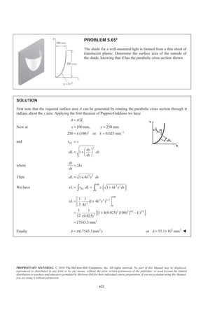
![PROPRIETARY MATERIAL. © 2010 The McGraw-Hill Companies, Inc. All rights reserved. No part of this Manual may be displayed,
reproduced or distributed in any form or by any means, without the prior written permission of the publisher, or used beyond the limited
distribution to teachers and educators permitted by McGraw-Hill for their individual course preparation. If you are a student using this Manual,
you are using it without permission.
610
PROBLEM 5.56
Determine the volume and the surface area of the chain link
shown, which is made from a 6-mm-diameter bar, if R = 10 mm
and L = 30 mm.
SOLUTION
The area A and circumference C of the cross section of the bar are
2
and .
4
A d C d
π
π= =
Also, the semicircular ends of the link can be obtained by rotating the cross section through a horizontal
semicircular arc of radius R. Now, applying the theorems of Pappus-Guldinus, we have for the volume V:
side end2( ) 2( )
2( ) 2( )
2( )
V V V
AL RA
L R A
π
π
= +
= +
= +
or 2
2[30 mm (10 mm)] (6 mm)
4
V
π
π
ª º
= + « »
¬ ¼
3
3470 mm= 3
or 3470 mmV = W
For the area A: side end2( ) 2( )
2( ) 2( )
2( )
A A A
CL RC
L R C
π
π
= +
= +
= +
or 2[30 mm (10 mm)][ (6 mm)]A π π= +
2
2320 mm= 2
or 2320 mmA = W](https://image.slidesharecdn.com/mecanica-151208044028-lva1-app6892/85/Mecanica-621-320.jpg)
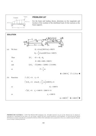
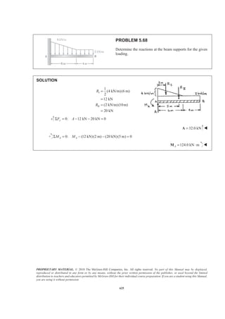
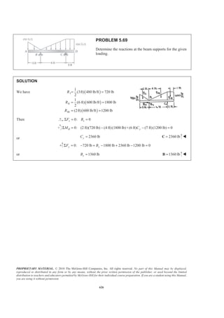
![PROPRIETARY MATERIAL. © 2010 The McGraw-Hill Companies, Inc. All rights reserved. No part of this Manual may be displayed,
reproduced or distributed in any form or by any means, without the prior written permission of the publisher, or used beyond the limited
distribution to teachers and educators permitted by McGraw-Hill for their individual course preparation. If you are a student using this Manual,
you are using it without permission.
614
PROBLEM 5.60
Three different drive belt profiles are to be
studied. If at any given time each belt makes
contact with one-half of the circumference of
its pulley, determine the contact area between
the belt and the pulley for each design.
SOLUTION SOLUTION
Applying the first theorem of Pappus-Guldinus, the contact area CA of a belt
is given by:
CA yL yLπ π= = Σ
where the individual lengths are the lengths of the belt cross section that are
in contact with the pulley.
(a) 1 1 2 2[2( ) ]
0.125 0.125 in.
2 3 in. [(3 0.125)in.](0.625 in.)
2 cos20
CA y L y Lπ
π
= +
½ª º° °§ · ª º
= − + −® ¾« »¨ ¸ « »°© ¹ ¬ ¼° °¬ ¼¯ ¿
or 2
8.10 in.CA = W
(b) 1 1[2( )]
0.375 0.375 in.
2 3 0.08 in.
2 cos20
CA y Lπ
π
=
ª º§ · § ·
= − −« »¨ ¸ ¨ ¸°© ¹ © ¹¬ ¼
or 2
6.85 in.CA = W
(c) 1 1[2( )]
2(0.25)
3 in. [ (0.25 in.)]
CA y Lπ
π π
π
=
ª º§ ·
= −« »¨ ¸
© ¹¬ ¼
or 2
7.01in.CA = W](https://image.slidesharecdn.com/mecanica-151208044028-lva1-app6892/85/Mecanica-625-320.jpg)
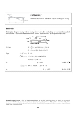
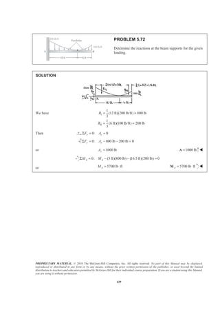
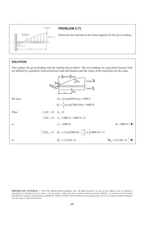
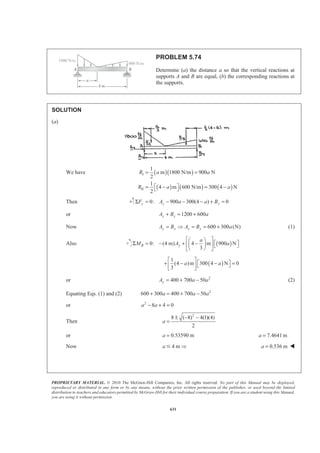
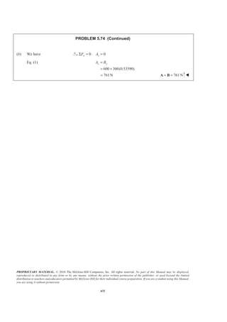
![PROPRIETARY MATERIAL. © 2010 The McGraw-Hill Companies, Inc. All rights reserved. No part of this Manual may be displayed,
reproduced or distributed in any form or by any means, without the prior written permission of the publisher, or used beyond the limited
distribution to teachers and educators permitted by McGraw-Hill for their individual course preparation. If you are a student using this Manual,
you are using it without permission.
620
PROBLEM 5.64
The wooden peg shown is turned from a dowel 1 in. in
diameter and 4 in. long. Determine the percentage of the
initial volume of the dowel that becomes waste.
SOLUTION
To obtain the solution it is first necessary to determine the volume of the peg. That volume can be generated
by rotating the area shown about the x axis.
The generating area is next divided into six components as indicated
0.5
sin 2
0.875
α =
or 2 34.850 17.425α α= ° = °
Applying the second theorem of Pappus-Guldinus and then using Figure 5.8a, we have
2 2PEGV YA yAπ π= = Σ
2
, in.A , in.y 3
, in.yA
1 0.5 0.25 0.125× × 0.125 0.015625
2
[3 0.875(1 cos34.850 ) 0.1875]
(0.3125) 0.82987
− − ° −
× =
0.15625 0.129667
3 0.1875 0.5 0.9375× × 0.25 0.023438
4 2
(0.1875) 0.027612
4
π
− = −
4 0.1875
0.5 0.42042
3π
×
− = 0.011609−
5 2
(0.875)α
2 0.875sin17.425
sin17.425
3α
× °
× ° 0.04005
6
1
(0.875cos34.850 )(0.5) 0.179517
2
− ° = −
1
(0.5) 0.166667
3
= 0.029920−
3
0.167252 in.yLΣ =](https://image.slidesharecdn.com/mecanica-151208044028-lva1-app6892/85/Mecanica-631-320.jpg)
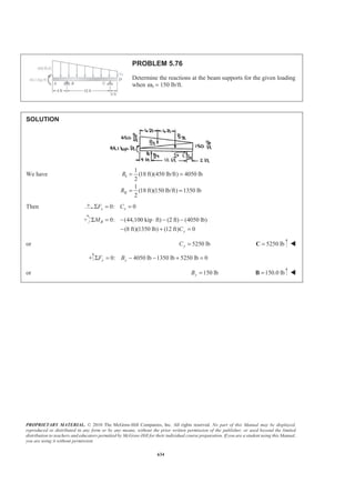
![PROPRIETARY MATERIAL. © 2010 The McGraw-Hill Companies, Inc. All rights reserved. No part of this Manual may be displayed,
reproduced or distributed in any form or by any means, without the prior written permission of the publisher, or used beyond the limited
distribution to teachers and educators permitted by McGraw-Hill for their individual course preparation. If you are a student using this Manual,
you are using it without permission.
622
PROBLEM 5.65*
The shade for a wall-mounted light is formed from a thin sheet of
translucent plastic. Determine the surface area of the outside of
the shade, knowing that it has the parabolic cross section shown.
SOLUTION
First note that the required surface area A can be generated by rotating the parabolic cross section through π
radians about the y axis. Applying the first theorem of Pappus-Guldinus we have
A xLπ=
Now at
2 1
100 mm, 250 mm
250 (100) or 0.025 mm
x y
k k −
= =
= =
and
2
1
ELx x
dy
dL dx
dx
=
§ ·
= + ¨ ¸
© ¹
where 2
dy
kx
dx
=
Then 2 2
1 4dL k x dx= +
We have ( )100
2 2
0
1 4ELxL x dL x k x dx= = +³ ³
{ }
100
2 2 3/2
2
0
2 2 3/2 3/2
2
2
1 1
(1 4 )
3 4
1 1
[1 4(0.025) (100) ] (1)
12 (0.025)
17543.3 mm
xL k x
k
ª º
= +« »
¬ ¼
= + −
=
Finally 2
(17543.3 mm )A π= or 3 2
55.1 10 mmA = × W](https://image.slidesharecdn.com/mecanica-151208044028-lva1-app6892/85/Mecanica-633-320.jpg)
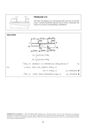
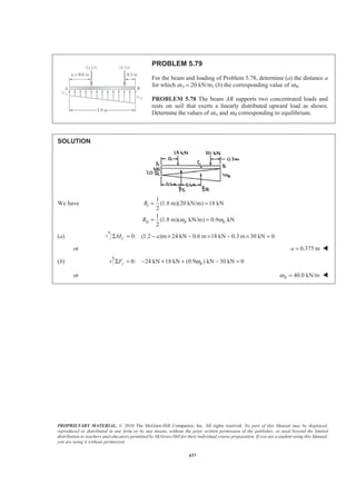
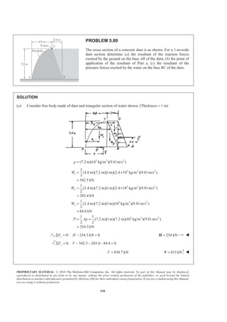
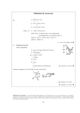
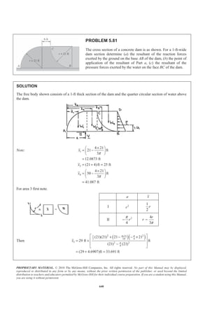
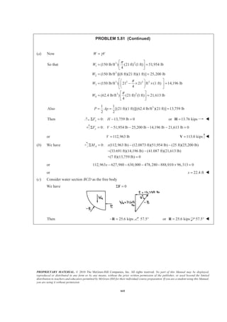
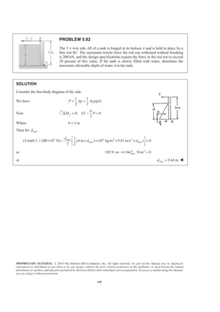
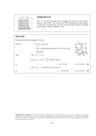
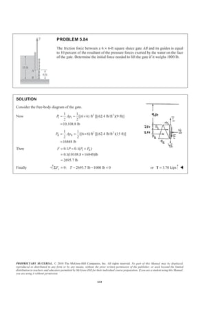
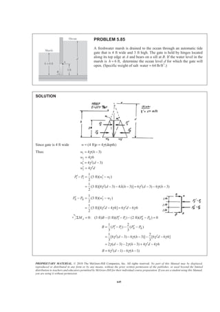
 300(4 ) N
2
R a a
R a a
= =
= − = −
Then ( ) ( )
8
0: m (900 N) m 300 4 N 4 m 0
3 3
A y
a a
M a a B
+§ · § ·
ª ºΣ = − − − + =¨ ¸ ¨ ¸¬ ¼
© ¹ © ¹
or 2
50 100 800yB a a= − + (1)
Then 100 100 0
ydB
a
da
= − = or 1.000 ma = W
(b) Eq. (1) 2
50(1) 100(1) 800 750 NyB = − + = 750 N=B W
and 0: 0x xF AΣ = =
0: 900(1)N 300(4 1)N 750 N 0y yF AΣ = − − − + =
or 1050 NyA = 1050 N=A W](https://image.slidesharecdn.com/mecanica-151208044028-lva1-app6892/85/Mecanica-644-320.jpg)
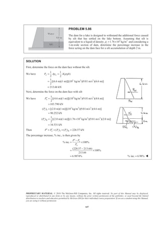
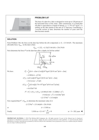
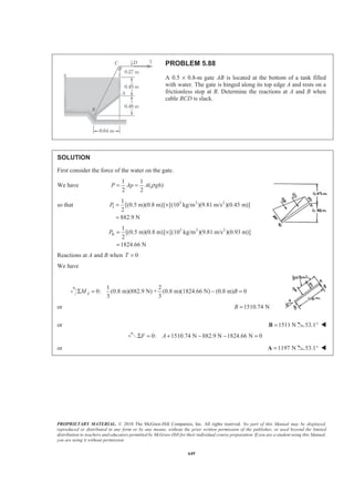
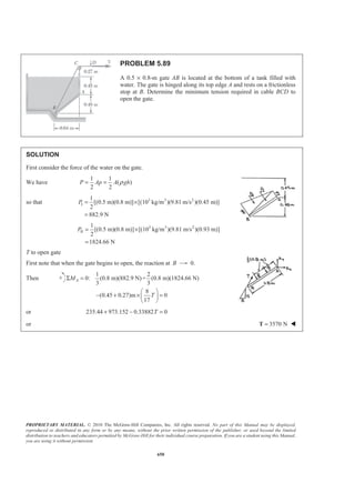
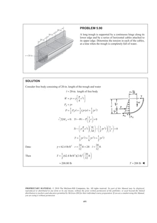
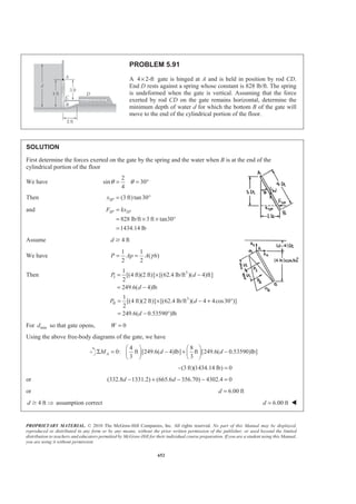
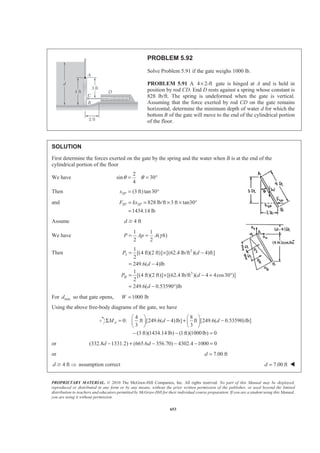
![PROPRIETARY MATERIAL. © 2010 The McGraw-Hill Companies, Inc. All rights reserved. No part of this Manual may be displayed,
reproduced or distributed in any form or by any means, without the prior written permission of the publisher, or used beyond the limited
distribution to teachers and educators permitted by McGraw-Hill for their individual course preparation. If you are a student using this Manual,
you are using it without permission.
641
PROBLEM 5.81 (Continued)
(a) Now W Vγ=
So that 3 2
1
3
2
3 2 2 2
3
3 2
4
(150 lb/ft ) (21 ft) (1 ft) 51,954 lb
4
(150 lb/ft )[(8 ft)(21 ft)(1 ft)] 25,200 lb
(150 lb/ft ) 21 21 ft (1 ft) 14,196 lb
4
(62.4 lb/ft ) (21 ft) (1 ft) 21,613 lb
4
W
W
W
W
π
π
π
ª º
= =« »
¬ ¼
= =
ª º§ ·
= − × × =« »¨ ¸
© ¹¬ ¼
ª º
= =« »
¬ ¼
Also 31 1
[(21 ft)(1 ft)][(62.4 lb/ft )(21 ft)] 13,759 lb
2 2
P Ap= = =
Then 0: 13,759 lb 0xF HΣ = − = or 13.76 kips=H W
0: 51,954 lb 25,200 lb 14,196 lb 21,613 lb 0yF VΣ = − − − − =
or 112,963 lbV = 113.0 kips=V W
(b) We have 0: (112,963 lb) (12.0873 ft)(51,954 lb) (25 ft)(25,200 lb)
(33.691 ft)(14,196 lb) (41.087 ft)(21,613 lb)
+(7 ft)(13,759 lb) 0
AM xΣ = − −
− −
=
or 112,963 627,980 630,000 478,280 888,010 96,313 0x − − − − + =
or 22.4 ftx = W
(c) Consider water section BCD as the free body
We have 0Σ =F
Then 25.6 kips− =R 57.5° or 25.6 kips=R 57.5° W](https://image.slidesharecdn.com/mecanica-151208044028-lva1-app6892/85/Mecanica-652-320.jpg)
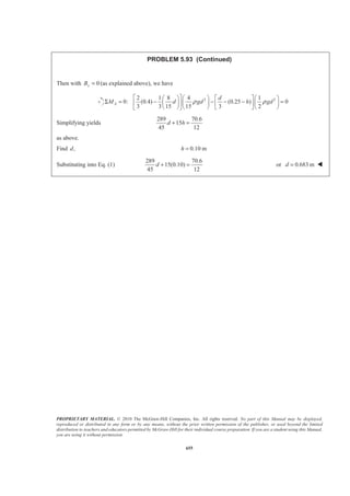
![PROPRIETARY MATERIAL. © 2010 The McGraw-Hill Companies, Inc. All rights reserved. No part of this Manual may be displayed,
reproduced or distributed in any form or by any means, without the prior written permission of the publisher, or used beyond the limited
distribution to teachers and educators permitted by McGraw-Hill for their individual course preparation. If you are a student using this Manual,
you are using it without permission.
643
PROBLEM 5.83
The 3 × 4-m side of an open tank is hinged at its bottom A and is held in
place by a thin rod BC. The tank is to be filled with glycerine, whose density
is 1263 kg/m3
. Determine the force T in the rod and the reactions at the hinge
after the tank is filled to a depth of 2.9 m.
SOLUTION
Consider the free-body diagram of the side.
We have
3 2
1 1
( )
2 2
1
[(2.9 m)(4 m)] [(1263 kg/m )(9.81 m/s )(2.9 m)]
2
= 208.40 kN
P Ap A gdρ= =
=
Then 0: 0y yF AΣ = =
2.9
0: (3 m) m (208.4 kN) 0
3
AM T
§ ·
Σ = − =¨ ¸
© ¹
or 67.151 kNT = 67.2 kN=T W
0: 208.40 kN 67.151 kN 0x xF AΣ = + − =
or 141.249 kNxA = − 141.2 kN=A W](https://image.slidesharecdn.com/mecanica-151208044028-lva1-app6892/85/Mecanica-654-320.jpg)
![PROPRIETARY MATERIAL. © 2010 The McGraw-Hill Companies, Inc. All rights reserved. No part of this Manual may be displayed,
reproduced or distributed in any form or by any means, without the prior written permission of the publisher, or used beyond the limited
distribution to teachers and educators permitted by McGraw-Hill for their individual course preparation. If you are a student using this Manual,
you are using it without permission.
644
PROBLEM 5.84
The friction force between a 6 × 6-ft square sluice gate AB and its guides is equal
to 10 percent of the resultant of the pressure forces exerted by the water on the face
of the gate. Determine the initial force needed to lift the gate if it weighs 1000 lb.
SOLUTION
Consider the free-body diagram of the gate.
Now 2 3
I I
1 1
[(6 6) ft ][(62.4 lb/ft )(9 ft)]
2 2
10,108.8 lb
P Ap= = ×
=
2 3
II II
1 1
[(6 6)ft ][(62.4 lb/ft )(15 ft)]
2 2
16848 lb
P Ap= = ×
=
Then I II0.1 0.1( )
0.1(10108.8 16848)lb
2695.7 lb
F P P P= = +
= +
=
Finally 0: 2695.7 lb 1000 lb 0yF TΣ = − − = or 3.70 kips=T W](https://image.slidesharecdn.com/mecanica-151208044028-lva1-app6892/85/Mecanica-655-320.jpg)
![PROPRIETARY MATERIAL. © 2010 The McGraw-Hill Companies, Inc. All rights reserved. No part of this Manual may be displayed,
reproduced or distributed in any form or by any means, without the prior written permission of the publisher, or used beyond the limited
distribution to teachers and educators permitted by McGraw-Hill for their individual course preparation. If you are a student using this Manual,
you are using it without permission.
645
PROBLEM 5.85
A freshwater marsh is drained to the ocean through an automatic tide
gate that is 4 ft wide and 3 ft high. The gate is held by hinges located
along its top edge at A and bears on a sill at B. If the water level in the
marsh is 6 ft,h = determine the ocean level d for which the gate will
open. (Specific weight of salt 3
water 64 lb/ft .)=
SOLUTION
Since gate is 4 ft wide (4 ft) 4 (depth)w p γ= =
Thus: 1
2
1
2
4 ( 3)
4
4 ( 3)
4
γ
γ
γ
γ
= −
=
′ ′= −
′ ′=
w h
w h
w d
w d
I I 1 1
1
(3 ft)( )
2
1
(3 ft)[4 ( 3) 4 ( 3)] 6 ( 3) 6 ( 3)
2
P P w w
d h d hγ λ γ γ
′ ′− = −
′ ′= − − − = − − −
II II 2 2
1
(3 ft)( )
2
1
(3 ft)[4 4 ] 6 6
2
P P w w
d h d hγ γ γ γ
′ ′− = −
′ ′= − = −
I I II II0: (3 ft) (1 ft)( ) (2 ft)( ) 0AM B P P P P′ ′Σ = − − − − =
I I II II
1 2
( ) ( )
3 3
1 2
[6 ( 3) 6 ( 3)] [6 6 ]
3 3
2 ( 3) 2 ( 3) 4 4
B P P P P
d h d h
d h d h
γ γ γ γ
γ γ γ γ
′ ′= − − −
′ ′= − − − − −
′= − − − + −
6 ( 1) 6 ( 1)B d hγ γ′= − − −](https://image.slidesharecdn.com/mecanica-151208044028-lva1-app6892/85/Mecanica-656-320.jpg)
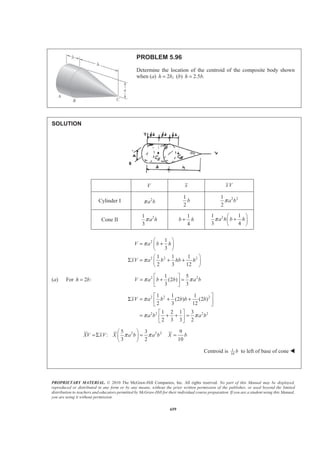
![PROPRIETARY MATERIAL. © 2010 The McGraw-Hill Companies, Inc. All rights reserved. No part of this Manual may be displayed,
reproduced or distributed in any form or by any means, without the prior written permission of the publisher, or used beyond the limited
distribution to teachers and educators permitted by McGraw-Hill for their individual course preparation. If you are a student using this Manual,
you are using it without permission.
647
PROBLEM 5.86
The dam for a lake is designed to withstand the additional force caused
by silt that has settled on the lake bottom. Assuming that silt is
equivalent to a liquid of density 3 3
1.76 10 kg/msρ = × and considering a
1-m-wide section of dam, determine the percentage increase in the
force acting on the dam face for a silt accumulation of depth 2 m.
SOLUTION
First, determine the force on the dam face without the silt.
We have
3 3 2
1 1
( )
2 2
1
[(6.6 m)(1 m)][(10 kg/m )(9.81 m/s )(6.6 m)]
2
213.66 kN
w wP Ap A ghρ= =
=
=
Next, determine the force on the dam face with silt
We have 3 3 2
3 3 2
I
3 3 2
II
1
[(4.6 m)(1 m)][(10 kg/m )(9.81m/s )(4.6 m)]
2
103.790 kN
( ) [(2.0 m)(1 m)][(10 kg/m )(9.81 m/s )(4.6 m)]
90.252 kN
1
( ) [(2.0 m)(1 m)][(1.76 10 kg/m )(9.81 m/s )(2.0 m)]
2
34.531 kN
w
s
s
P
P
P
′ =
=
=
=
= ×
=
Then I II( ) ( ) 228.57 kNw s sP P P P′ ′= + + =
The percentage increase, % inc., is then given by
% inc. 100%
(228.57 213.66)
100%
213.66
6.9874%
′ −
= ×
−
= ×
=
w
w
P P
P
% inc. 6.98%= W](https://image.slidesharecdn.com/mecanica-151208044028-lva1-app6892/85/Mecanica-658-320.jpg)
![PROPRIETARY MATERIAL. © 2010 The McGraw-Hill Companies, Inc. All rights reserved. No part of this Manual may be displayed,
reproduced or distributed in any form or by any means, without the prior written permission of the publisher, or used beyond the limited
distribution to teachers and educators permitted by McGraw-Hill for their individual course preparation. If you are a student using this Manual,
you are using it without permission.
648
PROBLEM 5.87
The base of a dam for a lake is designed to resist up to 120 percent of
the horizontal force of the water. After construction, it is found that
silt (that is equivalent to a liquid of density 3 3
1.76 10 kg/m )sρ = × is
settling on the lake bottom at the rate of 12 mm/year. Considering a
1-m-wide section of dam, determine the number of years until the
dam becomes unsafe.
SOLUTION
From Problem 5.86, the force on the dam face before the silt is deposited, is 213.66 kN.wP = The maximum
allowable force allowP on the dam is then:
allow 1.2 (1.5)(213.66 kN) 256.39 kNwP P= = =
Next determine the force P′on the dam face after a depth d of silt has settled
We have 3 3 2
2
3 3 2
I
2
3 3 2
II
2
1
[(6.6 )m (1 m)][(10 kg/m )(9.81m/s )(6.6 )m]
2
4.905(6.6 ) kN
( ) [ (1 m)][(10 kg/m )(9.81m/s )(6.6 )m]
9.81(6.6 )kN
1
( ) [ (1m)][(1.76 10 kg/m )(9.81m/s )( )m]
2
8.6328 kN
w
s
s
P d d
d
P d d
d d
P d d
d
′ = − × −
= −
= −
= −
= ×
=
2
I II
2 2
2
( ) ( ) [4.905(43.560 13.2000 )
9.81(6.6 ) 8.6328 ]kN
[3.7278 213.66]kN
w s sP P P P d d
d d d
d
′ ′= + + = − +
+ − +
= +
Now required that allowP P′ = to determine the maximum value of d.
2
(3.7278 213.66)kN 256.39 kNd + =
or 3.3856 md =
Finally 3 m
3.3856 m 12 10 N
year
−
= × × or 282 yearsN = W](https://image.slidesharecdn.com/mecanica-151208044028-lva1-app6892/85/Mecanica-659-320.jpg)
![PROPRIETARY MATERIAL. © 2010 The McGraw-Hill Companies, Inc. All rights reserved. No part of this Manual may be displayed,
reproduced or distributed in any form or by any means, without the prior written permission of the publisher, or used beyond the limited
distribution to teachers and educators permitted by McGraw-Hill for their individual course preparation. If you are a student using this Manual,
you are using it without permission.
649
PROBLEM 5.88
A 0.5 × 0.8-m gate AB is located at the bottom of a tank filled
with water. The gate is hinged along its top edge A and rests on a
frictionless stop at B. Determine the reactions at A and B when
cable BCD is slack.
SOLUTION
First consider the force of the water on the gate.
We have
1 1
( )
2 2
ρ= =P Ap A gh
so that 3 3 2
I
1
[(0.5 m)(0.8 m)] [(10 kg/m )(9.81 m/s )(0.45 m)]
2
882.9 N
P = ×
=
3 3 2
II
1
[(0.5 m)(0.8 m)] [(10 kg/m )(9.81 m/s )(0.93 m)]
2
1824.66 N
P = ×
=
Reactions at A and B when 0T =
We have
1 2
0: (0.8 m)(882.9 N) + (0.8 m)(1824.66 N) (0.8 m) 0
3 3
AM BΣ = − =
or 1510.74 NB =
or 1511 N=B 53.1° W
0: 1510.74 N 882.9 N 1824.66 N 0F AΣ = + − − =
or 1197 N=A 53.1° W](https://image.slidesharecdn.com/mecanica-151208044028-lva1-app6892/85/Mecanica-660-320.jpg)
![PROPRIETARY MATERIAL. © 2010 The McGraw-Hill Companies, Inc. All rights reserved. No part of this Manual may be displayed,
reproduced or distributed in any form or by any means, without the prior written permission of the publisher, or used beyond the limited
distribution to teachers and educators permitted by McGraw-Hill for their individual course preparation. If you are a student using this Manual,
you are using it without permission.
650
PROBLEM 5.89
A 0.5 × 0.8-m gate AB is located at the bottom of a tank filled with
water. The gate is hinged along its top edge A and rests on a frictionless
stop at B. Determine the minimum tension required in cable BCD to
open the gate.
SOLUTION
First consider the force of the water on the gate.
We have
1 1
( )
2 2
ρ= =P Ap A gh
so that 3 3 2
I
1
[(0.5 m)(0.8 m)] [(10 kg/m )(9.81 m/s )(0.45 m)]
2
882.9 N
P = ×
=
3 3 2
II
1
[(0.5 m)(0.8 m)] [(10 kg/m )(9.81 m/s )(0.93 m)]
2
1824.66 N
P = ×
=
T to open gate
First note that when the gate begins to open, the reaction at B 0.
Then
1 2
0: (0.8 m)(882.9 N)+ (0.8 m)(1824.66 N)
3 3
8
(0.45 0.27)m 0
17
AM
T
Σ =
§ ·
− + × =¨ ¸
© ¹
or 235.44 973.152 0.33882 0T+ − =
or 3570 N=T W](https://image.slidesharecdn.com/mecanica-151208044028-lva1-app6892/85/Mecanica-661-320.jpg)
![PROPRIETARY MATERIAL. © 2010 The McGraw-Hill Companies, Inc. All rights reserved. No part of this Manual may be displayed,
reproduced or distributed in any form or by any means, without the prior written permission of the publisher, or used beyond the limited
distribution to teachers and educators permitted by McGraw-Hill for their individual course preparation. If you are a student using this Manual,
you are using it without permission.
652
PROBLEM 5.91
A 4 2-ft× gate is hinged at A and is held in position by rod CD.
End D rests against a spring whose constant is 828 lb/ft. The spring
is undeformed when the gate is vertical. Assuming that the force
exerted by rod CD on the gate remains horizontal, determine the
minimum depth of water d for which the bottom B of the gate will
move to the end of the cylindrical portion of the floor.
SOLUTION
First determine the forces exerted on the gate by the spring and the water when B is at the end of the
cylindrical portion of the floor
We have
2
sin 30
4
θ θ= = °
Then (3 ft)tan30SPx = °
and
828 lb/ft 3 ft tan30°
1434.14 lb
SP SPF kx=
= × ×
=
Assume 4 ftd Ն
We have
1 1
( )
2 2
γ= =P Ap A h
Then 3
I
1
[(4 ft)(2 ft)] [(62.4 lb/ft )( 4)ft]
2
249.6( 4)lb
P d
d
= × −
= −
3
II
1
[(4 ft)(2 ft)] [(62.4 lb/ft )( 4 4cos30 )]
2
249.6( 0.53590 )lb
P d
d
= × − + °
= − °
For mind so that gate opens, 0W =
Using the above free-body diagrams of the gate, we have
4 8
0: ft [249.6( 4)lb] ft [249.6( 0.53590)lb]
3 3
AM d d
§ · § ·
Σ = − + −¨ ¸ ¨ ¸
© ¹ © ¹
(3 ft)(1434.14 lb) 0− =
or (332.8 1331.2) (665.6 356.70) 4302.4 0d d− + − − =
or 6.00 ftd =
4 ftd ŸՆ assumption correct 6.00 ftd = W](https://image.slidesharecdn.com/mecanica-151208044028-lva1-app6892/85/Mecanica-663-320.jpg)
![PROPRIETARY MATERIAL. © 2010 The McGraw-Hill Companies, Inc. All rights reserved. No part of this Manual may be displayed,
reproduced or distributed in any form or by any means, without the prior written permission of the publisher, or used beyond the limited
distribution to teachers and educators permitted by McGraw-Hill for their individual course preparation. If you are a student using this Manual,
you are using it without permission.
653
PROBLEM 5.92
Solve Problem 5.91 if the gate weighs 1000 lb.
PROBLEM 5.91 A 4 2-ft× gate is hinged at A and is held in
position by rod CD. End D rests against a spring whose constant is
828 lb/ft. The spring is undeformed when the gate is vertical.
Assuming that the force exerted by rod CD on the gate remains
horizontal, determine the minimum depth of water d for which the
bottom B of the gate will move to the end of the cylindrical portion
of the floor.
SOLUTION
First determine the forces exerted on the gate by the spring and the water when B is at the end of the
cylindrical portion of the floor
We have
2
sin 30
4
θ θ= = °
Then (3 ft)tan30SPx = °
and 828 lb/ft 3 ft tan30°
1434.14 lb
SP SPF kx= = × ×
=
Assume 4 ftd Ն
We have
1 1
( )
2 2
γ= =P Ap A h
Then 3
I
1
[(4 ft)(2 ft)] [(62.4 lb/ft )( 4)ft]
2
249.6( 4)lb
P d
d
= × −
= −
3
II
1
[(4 ft)(2 ft)] [(62.4 lb/ft )( 4 4cos30 )]
2
249.6( 0.53590 )lb
P d
d
= × − + °
= − °
For mind so that gate opens, 1000 lb=W
Using the above free-body diagrams of the gate, we have
4 8
0: ft [249.6( 4)lb] ft [249.6( 0.53590)lb]
3 3
(3 ft)(1434.14 lb) (1ft)(1000lb) 0
AM d d
§ · § ·
Σ = − + −¨ ¸ ¨ ¸
© ¹ © ¹
− − =
or (332.8 1331.2) (665.6 356.70) 4302.4 1000 0− + − − − =d d
or 7.00 ftd =
4 ftd ŸՆ assumption correct 7.00 ftd = W](https://image.slidesharecdn.com/mecanica-151208044028-lva1-app6892/85/Mecanica-664-320.jpg)
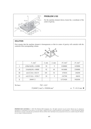
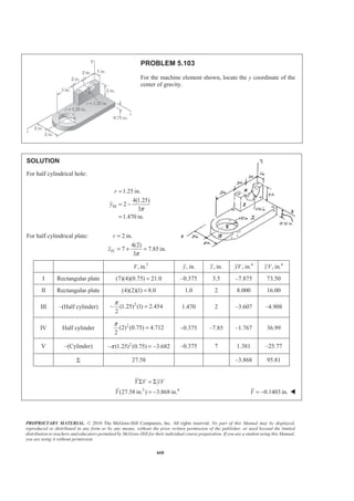
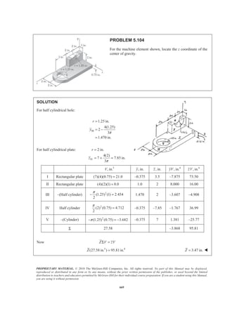
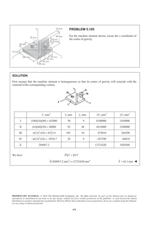
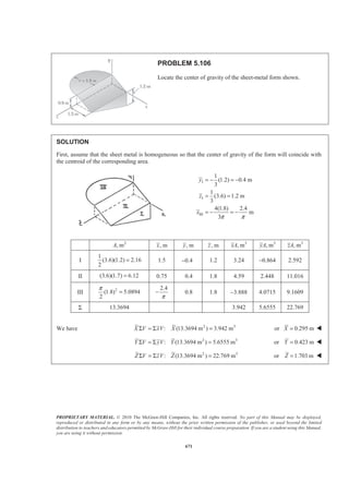
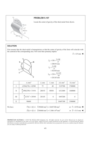
![PROPRIETARY MATERIAL. © 2010 The McGraw-Hill Companies, Inc. All rights reserved. No part of this Manual may be displayed,
reproduced or distributed in any form or by any means, without the prior written permission of the publisher, or used beyond the limited
distribution to teachers and educators permitted by McGraw-Hill for their individual course preparation. If you are a student using this Manual,
you are using it without permission.
660
PROBLEM 5.96 (Continued)
(b) For 2.5 :h b= 2 21
(2.5 ) 1.8333
3
V a b b a bπ π
ª º
= + =« »
¬ ¼
2 2 2
2 2
2 2
1 1 1
(2.5 ) (2.5 )
2 3 12
[0.5 0.8333 0.52083]
1.85416
xV a b b b b
a b
a b
π
π
π
ª º
Σ = + +« »
¬ ¼
= + +
=
2 2 2
: (1.8333 ) 1.85416 1.01136XV xV X a b a b X bπ π= Σ = =
Centroid is 0.01136b to right of base of cone W
Note: Centroid is at base of cone for 6 2.449h b b= =](https://image.slidesharecdn.com/mecanica-151208044028-lva1-app6892/85/Mecanica-671-320.jpg)
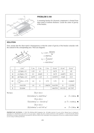
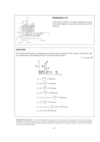
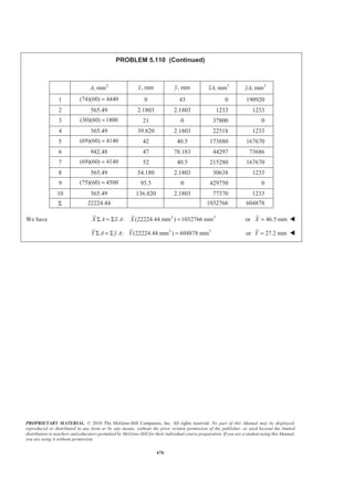
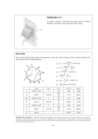
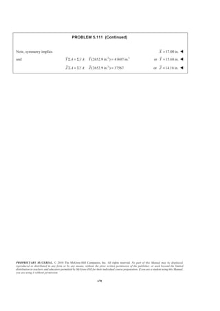
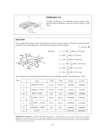
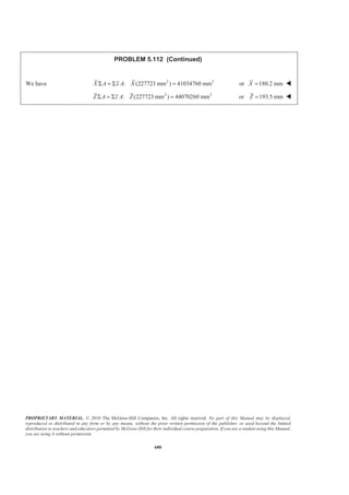
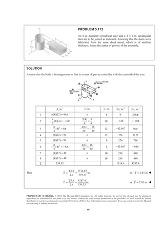
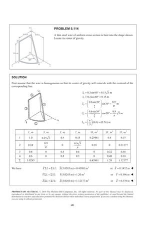
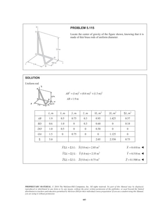
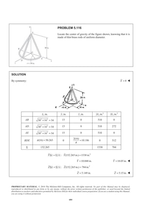
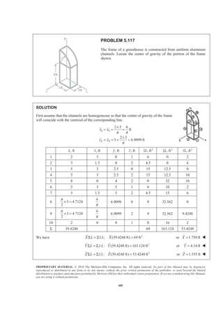
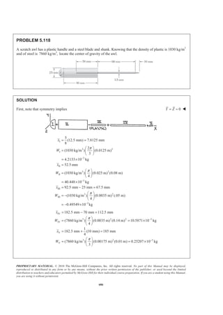
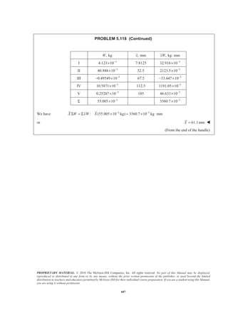
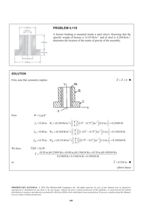
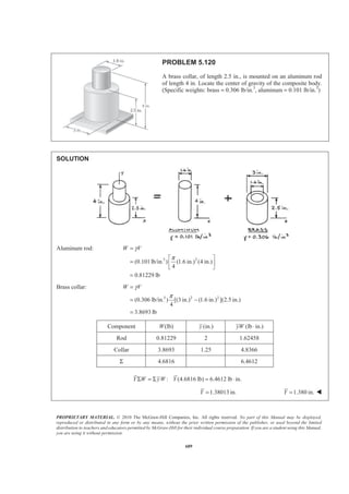
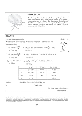
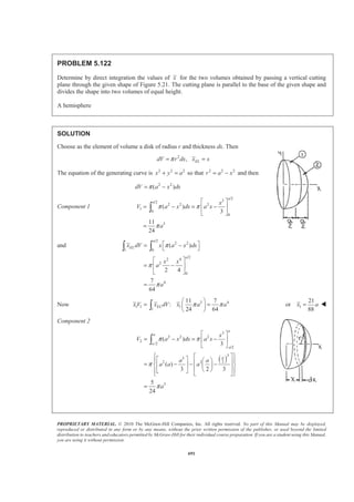
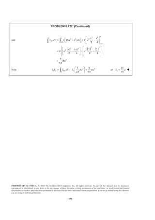
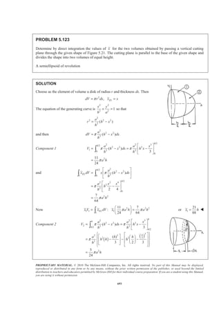
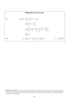

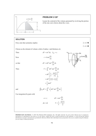

4
3.8693 lb
W Vγ
π
=
= −
=
Component W(lb) (in.)y (lb in.)yW ⋅
Rod 0.81229 2 1.62458
Collar 3.8693 1.25 4.8366
Σ 4.6816 6.4612
: (4.6816 lb) 6.4612 lb in.Y W yW YΣ = Σ = ⋅
1.38013 in.Y = 1.380 in.Y = W](https://image.slidesharecdn.com/mecanica-151208044028-lva1-app6892/85/Mecanica-700-320.jpg)
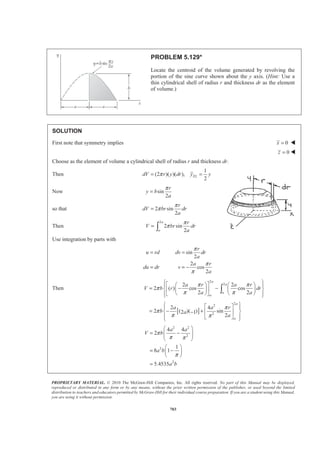
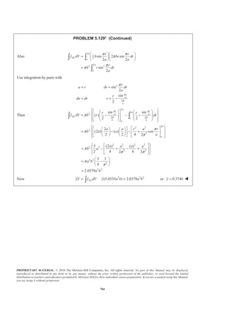
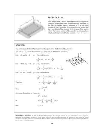
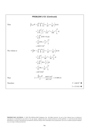
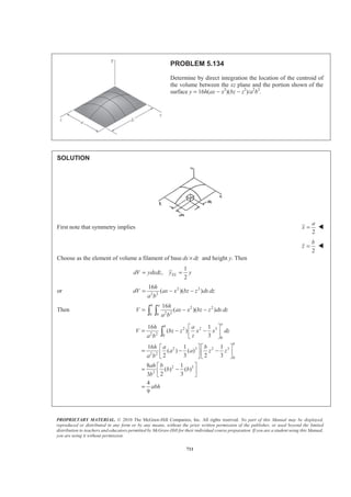
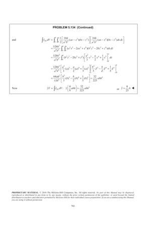
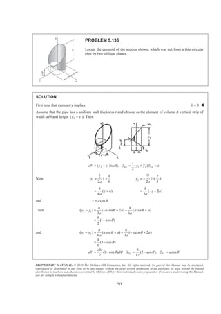
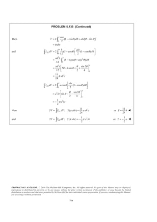
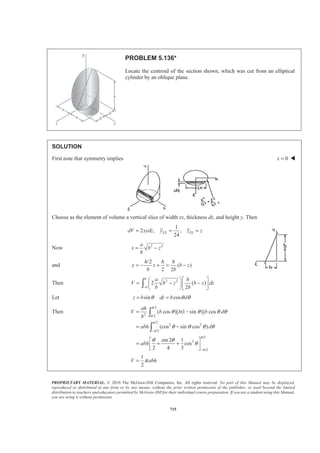
![PROPRIETARY MATERIAL. © 2010 The McGraw-Hill Companies, Inc. All rights reserved. No part of this Manual may be displayed,
reproduced or distributed in any form or by any means, without the prior written permission of the publisher, or used beyond the limited
distribution to teachers and educators permitted by McGraw-Hill for their individual course preparation. If you are a student using this Manual,
you are using it without permission.
703
PROBLEM 5.129*
Locate the centroid of the volume generated by revolving the
portion of the sine curve shown about the y axis. (Hint: Use a
thin cylindrical shell of radius r and thickness dr as the element
of volume.)
SOLUTION
First note that symmetry implies 0x = W
0z = W
Choose as the element of volume a cylindrical shell of radius r and thickness dr.
Then
1
(2 )( )( ),
2
ELdV r y dr y yπ= =
Now sin
2
r
y b
a
π
=
so that 2 sin
2
r
dV br dr
a
π
π=
Then
2
2 sin
2
a
a
r
V br dr
a
π
π= ³
Use integration by parts with
sin
2
2
cos
2
r
u rd dv dr
a
a r
du dr v
a
π
π
π
= =
= = −
Then
[ ]
2
2
2
2
2
2 2
2 ( ) cos cos
2 2
2 4
2 ( )( ) sin2 1
2
a
a
a
a
a
a
a r a r
V b r dr
a a
a a r
b a
a
π π
π
π π
π
π
π π
½ª º° °§ · § ·
= − −® ¾« »¨ ¸ ¨ ¸
© ¹ © ¹¬ ¼° °¯ ¿
½ª º° °
= − +® ¾« »−
¬ ¼° °¯ ¿
³
2 2
2
2
2
4 4
2
1
8 1
5.4535
a a
V b
a b
a b
π
π π
π
§ ·
= −¨ ¸¨ ¸
© ¹
§ ·
= −¨ ¸
© ¹
=](https://image.slidesharecdn.com/mecanica-151208044028-lva1-app6892/85/Mecanica-714-320.jpg)
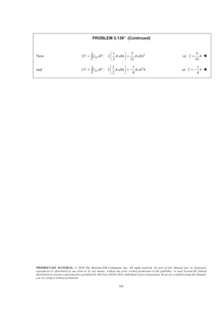
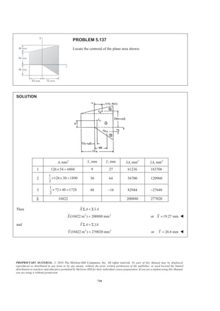
![PROPRIETARY MATERIAL. © 2010 The McGraw-Hill Companies, Inc. All rights reserved. No part of this Manual may be displayed,
reproduced or distributed in any form or by any means, without the prior written permission of the publisher, or used beyond the limited
distribution to teachers and educators permitted by McGraw-Hill for their individual course preparation. If you are a student using this Manual,
you are using it without permission.
706
PROBLEM 5.131
Determine by direct integration the location of the centroid of one-half of a
thin, uniform hemispherical shell of radius R.
SOLUTION
First note that symmetry implies 0x = W
The element of area dA of the shell shown is obtained by cutting the shell with two planes parallel to the xy
plane. Now
( )( )
2
EL
dA r Rd
r
y
π θ
π
=
= −
Where sinr R θ=
so that 2
sin
2
sinEL
dA R d
R
y
π θ θ
θ
π
=
= −
Then
/2
2 2 /2
0
0
2
sin [ cos ]A R d R
R
π
π
π θ θ π θ
π
= = −
=
³
and
/2
2
0
/2
3
0
3
2
sin ( sin )
sin 2
2
2 4
2
EL
R
y dA R d
R
R
π
π
θ π θ θ
π
θ θ
π
§ ·
= −¨ ¸
© ¹
ª º
= − −« »
¬ ¼
= −
³ ³
Now 2 3
: ( )
2
ELyA y dA y R R
π
π= = −³ or
1
2
y R= − W
Symmetry implies z y=
1
2
z R= − W](https://image.slidesharecdn.com/mecanica-151208044028-lva1-app6892/85/Mecanica-717-320.jpg)
![PROPRIETARY MATERIAL. © 2010 The McGraw-Hill Companies, Inc. All rights reserved. No part of this Manual may be displayed,
reproduced or distributed in any form or by any means, without the prior written permission of the publisher, or used beyond the limited
distribution to teachers and educators permitted by McGraw-Hill for their individual course preparation. If you are a student using this Manual,
you are using it without permission.
707
PROBLEM 5.132
The sides and the base of a punch bowl are of
uniform thickness t. If t RϽϽ and R = 250 mm,
determine the location of the center of gravity of
(a) the bowl, (b) the punch.
SOLUTION
(a) Bowl
First note that symmetry implies 0x = W
0z = W
for the coordinate axes shown below. Now assume that the bowl may be treated as a shell; the center of
gravity of the bowl will coincide with the centroid of the shell. For the walls of the bowl, an element of
area is obtained by rotating the arc ds about the y axis. Then
wall (2 sin )( )dA R Rdπ θ θ=
and wall( ) cosELy R θ= −
Then
/2
2
wall
/6
/22
/6
2
2 sin
2 [ cos ]
3
A R d
R
R
π
π
π
π
π θ θ
π θ
π
=
= −
=
³
and wall wall wall
/2
2
/6
/23 2
/6
3
( )
( cos )(2 sin )
[cos ]
3
4
ELy A y dA
R R d
R
R
π
π
π
π
θ π θ θ
π θ
π
=
= −
=
= −
³
³
By observation 2
base base
3
,
4 2
A R y R
π
= = −
Now y A yAΣ = Σ
or 2 2 3 23 3
3
4 4 4 2
y R R R R R
π π
π π
§ ·§ ·
+ = − + −¨ ¸¨ ¸ ¨ ¸© ¹ © ¹
or 0.48763 250 mmy R R= − = 121.9 mmy = − W](https://image.slidesharecdn.com/mecanica-151208044028-lva1-app6892/85/Mecanica-718-320.jpg)
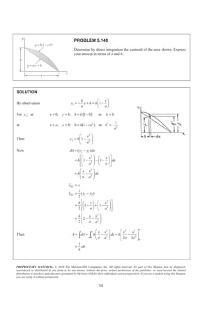
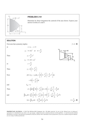
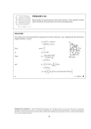
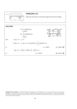
![PROPRIETARY MATERIAL. © 2010 The McGraw-Hill Companies, Inc. All rights reserved. No part of this Manual may be displayed,
reproduced or distributed in any form or by any means, without the prior written permission of the publisher, or used beyond the limited
distribution to teachers and educators permitted by McGraw-Hill for their individual course preparation. If you are a student using this Manual,
you are using it without permission.
714
PROBLEM 5.135 (Continued)
Then 0
0
2 (1 cos ) [ sin ]
2
aht
V d aht
aht
π
π
θ θ θ θ
π
= − = −
=
³
and
0
2
2
0
2
0
2
2 (5 cos ) (1 cos )
12 2
(5 6cos cos )
12
sin 2
5 6sin
12 2 4
11
24
EL
h aht
y dV d
ah t
d
ah t
ah t
π
π
π
θ θ θ
θ θ θ
θ θ
θ θ
π
ª º
= − −« »
¬ ¼
= − +
ª º
= − + +« »
¬ ¼
=
³ ³
³
0
2
0
2
2 cos (1 cos )
2
sin 2
sin
2 4
1
2
EL
aht
z dV a d
a ht
a ht
π
π
θ θ θ
θ θ
θ
π
ª º
= −« »
¬ ¼
ª º
= − −« »
¬ ¼
= −
³ ³
Now 211
: ( )
24
ELyV y dV y aht ah tπ π= =³ or
11
24
y h= W
and 21
: ( )
2
π π= = −³ ELzV z dV z aht a ht or
1
2
z a= − W](https://image.slidesharecdn.com/mecanica-151208044028-lva1-app6892/85/Mecanica-725-320.jpg)
![PROPRIETARY MATERIAL. © 2010 The McGraw-Hill Companies, Inc. All rights reserved. No part of this Manual may be displayed,
reproduced or distributed in any form or by any means, without the prior written permission of the publisher, or used beyond the limited
distribution to teachers and educators permitted by McGraw-Hill for their individual course preparation. If you are a student using this Manual,
you are using it without permission.
715
PROBLEM 5.136*
Locate the centroid of the section shown, which was cut from an elliptical
cylinder by an oblique plane.
SOLUTION
First note that symmetry implies 0x = W
Choose as the element of volume a vertical slice of width zx, thickness dz, and height y. Then
1
2 , ,
24
EL ELdV xydz y z z= = =
Now 2 2a
x b z
b
= −
and
/2
( )
2 2
= − + = −
h h h
y z b z
b b
Then 2 2
2 ( )
2−
§ ·ª º
= − −¨ ¸« »
© ¹¬ ¼³
b
b
a h
V b z b z dz
b b
Let sin cosz b dz b dθ θ θ= =
Then
/2
2 /2
/2
2 2
/2
/2
3
/2
( cos )[ (1 sin )] cos
(cos sin cos )
sin 2 1
cos
2 4 3
1
2
π
π
π
π
π
π
θ θ θ θ
θ θ θ θ
θ θ
θ
π
−
−
= −
= −
ª º
= + +« »
¬ ¼
=
³
³
ah
V b b b d
b
abh d
abh
V abh](https://image.slidesharecdn.com/mecanica-151208044028-lva1-app6892/85/Mecanica-726-320.jpg)
![PROPRIETARY MATERIAL. © 2010 The McGraw-Hill Companies, Inc. All rights reserved. No part of this Manual may be displayed,
reproduced or distributed in any form or by any means, without the prior written permission of the publisher, or used beyond the limited
distribution to teachers and educators permitted by McGraw-Hill for their individual course preparation. If you are a student using this Manual,
you are using it without permission.
716
PROBLEM 5.136* (Continued)
and 2 2
2
2 2 2
3
1
( ) 2 ( )
2 2 2
1
( )
4
−
−
½ª º § ·ª º
= × − − −® ¾¨ ¸« » « »
¬ ¼ © ¹¬ ¼¯ ¿
= − −
³ ³
³
b
EL
b
b
b
h a h
y dV b z b z b z dz
b b b
ah
b z b z dz
b
Let sin cosz b dz b dθ θ θ= =
Then
2 /2
2
3 /2
/2
2 2 2 2 2
/2
1
[ (1 sin )] ( cos ) ( cos )
4
1
(cos 2sin cos sin cos )
4
π
π
π
π
θ θ θ θ
θ θ θ θ θ θ
−
−
= − ×
= − +
³ ³
³
EL
ah
y dV b b b d
b
abh d
Now 2 21 1
sin (1 cos2 ) cos (1 cos2 )
2 2
θ θ θ θ= − = +
So that 2 2 21
sin cos (1 cos 2 )
4
θ θ θ= −
Then
/2
2 2 2 2
/2
/2
2 3
/2
2
1 1
cos 2sin cos (1 cos 2 )
4 4
1 sin 2 1 1 1 sin 4
cos
4 2 4 3 4 4 2 8
5
32
ELy dV abh d
abh
abh
π
π
π
π
θ θ θ θ θ
θ θ θ θ
θ θ
π
−
−
ª º
= − + −« »
¬ ¼
ª º§ · § ·
= + + + − +« »¨ ¸ ¨ ¸
© ¹ © ¹¬ ¼
=
³ ³
Also 2 2
2 2
2
2 ( )
2
( )
−
−
½ª º
= − −® ¾« »
¬ ¼¯ ¿
= − −
³ ³
³
b
EL
b
b
b
a h
z dV z a z b z dz
b b
ah
z b z b z dz
b
Let sin cosz b dz b dθ θ θ= =
Then
/2
2 /2
/2
2 2 2 2
/2
( sin )[ (1 sin )]( cos ) ( cos )
(sin cos sin cos )
EL
ah
z dV b b b b d
b
ab h d
π
π
π
π
θ θ θ θ θ
θ θ θ θ θ
−
−
= − ×
= −
³ ³
³
Using 2 2 21
sin cos (1 cos 2 )
4
θ θ θ= − from above
/2
2 2 2
/2
1
sin cos (1 cos 2 )
4
ELz dV ab h d
π
π
θ θ θ θ
−
ª º
= − −« »
¬ ¼³ ³
/2
2 3 2
/2
1 1 1 sin 4 1
cos
3 4 4 2 8 8
ab h ab h
π
π
θ θ
θ θ π
−
ª º§ ·
= − − + + = −« »¨ ¸
© ¹¬ ¼](https://image.slidesharecdn.com/mecanica-151208044028-lva1-app6892/85/Mecanica-727-320.jpg)
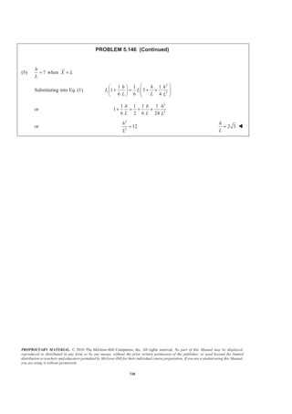

This document contains 15 multi-part problems involving the graphical and trigonometric determination of the magnitude and direction of the resultant force of two or more applied forces. The problems provide the magnitudes of the applied forces and ask the reader to use techniques like the parallelogram law, triangle rule, law of sines, and law of cosines to calculate the resultant force and various other requested values. Detailed step-by-step solutions are provided for each problem.


![Trigonometry [QEE-R 2012]](https://cdn.slidesharecdn.com/ss_thumbnails/qeereviewproblemswithsoln-120412063344-phpapp02-thumbnail.jpg?width=640&height=640&fit=bounds)