This chapter discusses Terzaghi's bearing capacity theory for determining the ultimate bearing capacity of shallow foundations. It summarizes the key assumptions of Terzaghi's theory, including homogeneous, isotropic soil; two-dimensional problem; general shear failure; and vertical, symmetrical loading. It describes the failure mechanism with three zones - an elastic central zone beneath the footing, and two radial shear zones on the sides that meet the ground surface at angles of 45° - φ/2. Terzaghi's theory uses a semi-empirical equation to calculate ultimate bearing capacity based on soil properties of cohesion, friction, and the effective overburden pressure at the foundation level.

![Shallow Foundation I: Ultimate Bearing Capacity 483
5. Estimate the cost of each of the promising types of foundation, and choose the type that
represents the most acceptable compromise between performance and cost.
12.2 THE ULTIMATE BEARING CAPACITY OF SOIL
Consider the simplest case of a shallow foundation subjected to a central vertical load. The footing
is founded at a depth Df below the ground surface [Fig. 12.2(a)]. If the settlement, 5, of the footing
is recorded against the applied load, Q, load-settlement curves, similar in shape to a stress-strain
curve, may be obtained as shown in Fig. 12.2(b).
The shape of the curve depends generally on the size and shape of the footing, the
composition of the supporting soil, and the character, rate, and frequency of loading. Normally a
curve will indicate the ultimate load Qu that the foundation can support. If the foundation soil is a
dense sand or a very stiff clay, the curve passes fairly abruptly to a peak value and then drops down
as shown by curve Cl in Fig. 10.2(b). The peak load Qu is quite pronounced in this case. On the
other hand, if the soil is loose sand or soft clay, the settlement curve continuesto descend on a slope
as shown by curve C2 which shows that the compression of soil is continuously taking place
without giving a definite value for Qu. On such a curve, Qu may be taken at a point beyond which
there is a constant rate of penetration.
12.3 SOME OF THE TERMS DEFINED
It will be useful to define, at this stage, some of the terms relating to bearing capacity of foundations
(refer to Fig. 12.3).
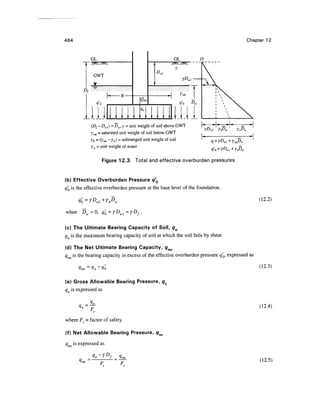
(a) Total Overburden Pressure q0
qo is the intensity of total overburden pressure due to the weight of both soil and water at the base
level of the foundation.
a —vD + v D {"1911
^n I U
MU ~ I int^w i
^-i
).
Q
L
Quit Load
(a) Footing (b) Load-settlement curves
Figure 12.2 Typical load-settlement curves](https://image.slidesharecdn.com/chapter12-220128191008/85/Chapter-12-3-320.jpg)


![Shallow Foundation I: Ultimate Bearing Capacity 491
c =0.67c
and tan 0 = 0.67 tan </> or 0 = tan'1
(0.67 tan <fi) (12.11)
The equations for the lower bound valuesfor the varioustypes of footings are as givenbelow.
Strip Foundation
qu =0.61cNc+yDfNc/ + yBNy (12.12)
Square Foundation
q +OAyBNy (12.13)
Circular Foundation
qu =O.S61cNc+yDfN(] + 03yBNy (12.14)
Rectangular Foundation
qu=Q.61c l +0.3x| NC +yDfNq +±yBNy l-02x| (12.15)
where N , N and N are the reduced bearing capacity factors for local shear failure.These factors
may be obtained either from Table 12.1 or Fig. 12.7 by making use of the friction angle (f> .
Ultimate Bearing Capacity qu in Purely Cohesionless and Cohesive Soils
Under General Shear Failure
Equations for the various types of footings for (c - 0) soil under general shear failure have been
given earlier. The same equations can be modifiedto give equationsfor cohesionless soil (for c =0)
and cohesive soils (for </> = 0) as follows.
It may be noted here that for c =0, the value of Nc =0, and for 0=0, the value of NC = 5.7 for
a strip footing and N = 1 .
a) Strip Footing
Forc = 0, qu=yDfNq+-yBNy (12.16)
For 0 = 0, qu =5.7c + yDf
b) Square Footing
For c = 0, qu =yDfNq+OAyBNr (12.17)
For 0 = 0, qu = 7.4c + yDf
c) Circular Footing
For c = 0, qu = yDfNq +Q3yBNy (12.18)](https://image.slidesharecdn.com/chapter12-220128191008/85/Chapter-12-11-320.jpg)


![500 Chapter 12
GL
"1
2
1
m
J
'
s S/K
L
-*—- 3 m - _HC,., =1.25m
1 . T f
t
Dw2= 1.25m
T 1
K
Case 1
Case 2
Figure Ex. 12.4 Effect of WT on bearing capacity
3484
Case 2—When Dw2 = 1.25 m (Fig. Ex. 12.4)
FromEq. (12.26b)
y=y =18.5kN/m3
* el ' m
1.25
y , = 8.69 + —-(18.5- 8.69) = 12.78 kN/m3
€ L 4.
= 30x57.8 +18.5x2x40.4+ -x 12.78x3x42.4 = 4042 kN/m2
4042
= 1347 kN/m2
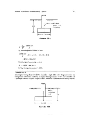
Example 12.5
A square footing fails by general shear in a cohesionless soil under an ultimate load of
Quh - 1687.5 kips. The footing is placed at a depth of 6.5 ft below ground level. Given 0 = 35°, and
7=110 Ib/ft3
, determinethe size of the footing if the water table is at a great depth (Fig. Ex. 12.5).
Solution
For a square footing [Eq. (12.17)] for c = 0, we have
For 0= 35°, Nq = 41.4, and Wy= 42.4 from Table 12.1.](https://image.slidesharecdn.com/chapter12-220128191008/85/Chapter-12-20-320.jpg)


![510 Chapter 12
punching shear failures is too conservative and ignores the existence of scale effects. It has been
conclusively established that the ultimate bearing capacity qu of soil does not increase in proportion
to the increase in the size of the footing as shown in Fig. 12.11 or otherwise the bearing capacity
factor Af decreases with the increase in the size of the footing as shown in Fig. 12.12.
In order to take into account the influence of soil compressibility and the related scale effects,
Vesic (1973) proposed a modification of Eq. (12.27) by introducing compressibility factors as
follows.
qu =cNcdcscCc+q'oNqdqsqCq + (12.28)
where, Cc, C and C are the soil compressibility factors. The other symbols remain the same as
before.
For the evaluation of the relative compressibility of a soil mass under loaded conditions,
Vesic introduced a term called rigidity index Ir, which is defined as
/ =
c +qtar0 (12.29)
where, G = shear modulus of soil = ^( + u]
Es = modulus of elasticity
q = effective overburden pressure at a depth equal to (ZX + 5/2)
600
400
200
100
80
60
3 40
20
10
8
6
4
2
1
I IT
Circular footings
Chattahoochee sand (vibrated)
Dry unit weight, 96.4 lb/ft3
Relative density, Dr = 0.79
Standard triaxial, 0 = 39°
Deep penetration resistance
(Measured) (Postulated) V;
Test plate sizes
Dutch cone size -* *
I I I I I I I
Usual footing sizes
I I I I I I
0.2 0.40.60.81.0 2 4 6 8 10
Footing size, ft
20 40 6080100 200
Figure 12.11 Variation of ultimate resistance of footings with size
(after Vesic, 1969)](https://image.slidesharecdn.com/chapter12-220128191008/85/Chapter-12-30-320.jpg)


![518 Chapter 12
When ex or e exceed a certain limit, Eq. (12.39) gives a negative value of q which indicates
tension between the soil and the bottom of the footing. Eqs (12.39) are applicable only when the
load is applied within a limited area which is known as the Kern as is shown shaded in Fig 12.15 so
that the load may fall within the shaded area to avoid tension. The procedure for the determination
of soil pressure when the load is applied outside the kern is laborious and as such not dealt with
here. However, charts are available for ready calculations in references such as Teng (1969) and
Highter and Anders (1985).
12.12 ULTIMATE BEARING CAPACITY OF FOOTINGS BASED ON
SPT VALUES (N]
Standard Energy Ratio Res Applicable to N Value
The effects of field procedures and equipment on the field values of N were discussed in Chapter 9.
The empirical correlations established in the USA between N and soil properties indicate the value
of N conforms to certain standard energy ratios. Some suggest 70% (Bowles, 1996) and others 60%
(Terzaghi et al., 1996). In order to avoid this confusion, the author uses Ncor in this book as the
corrected value for standard energy.
Cohesionless Soils
Relationship Between Ncor and <|>
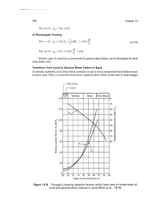
The relation between A^ and 0 established by Peck et al., (1974) is given in a graphical form in
Fig. 12.8. The value ofNcor to be used for getting 0 is the corrected value for standard energy. The
angle 0 obtained by this method can be used for obtaining the bearing capacity factors, and hence
the ultimate bearing capacity of soil.
Cohesive Soils
Relationship Between Ncor and qu (Unconfined Compressive Strength)
Relationships have been developed between Ncor and qu (the undrained compressive strength) for
the 0 = 0 condition. This relationship gives the value of cu for any known value of Ncor. The
relationship may be expressed as [Eq. (9.12)]
tf^^jA^CkPa) (12-40)
where the value of the coefficient & may vary from a minimum of 12 to a maximum of 25. A low
value of 13 yields qu given in Table 9.4.
Once qu is determined, the net ultimate bearing capacity and the net allowable bearing
pressure can be found following Skempton's approach.
12.13 THE CRT METHOD OF DETERMINING ULTIMATE BEARING
CAPACITY
Cohesionless Soils
Relationship Between qc, Dr and 0
Relationships between the static cone penetration resistance qc and 0 have been developed by
Robertson and Campanella (1983b), Fig. 9.15. The value of $ can therefore be determined with the
known value of q . With the known value of 0, bearing capacity factors can be determined and](https://image.slidesharecdn.com/chapter12-220128191008/85/Chapter-12-38-320.jpg)
![Shallow Foundation I: Ultimate Bearing Capacity 519
hence the ultimate bearing capacity. Experience indicates that the use of qc for obtaining 0 is more
reliable than the use of N.
Bearing Capacity of Soil
As per Schmertmann (1978), the bearing capacity factors N and N for use in the Terzaghi bearing
capacity equation can be determined by the use of the equation
N = (12.41)
where qc =cone point resistance in kg/cm2
(or tsf) averaged over a depth equal to the width below
the foundation.
Undrained Shear Strength
The undrained shear strength cu under 0 = 0 condition may be related to the static cone point
resistance qc as [Eq. (9.16)]
qc =N
kc
u+
Po
or c,, = (12.42)
where Nk = cone factor, may be taken as equal to 20 (Sanglerat, 1972) both for normally
consolidated and preconsolidated clays.
po = total overburden pressure
When once cu is known, the values of qm and qna can be evaluated as per the methods
explained in earlier sections.
Example 12.15
A water tank foundation has a footing of size 6 x 6 m founded at a depth of 3 m below ground level
in a medium dense sand stratum of great depth. The corrected average SPT value obtained from the
site investigation is 20. The foundation is subjected to a vertical load at an eccentricity of fi/10
along one of the axes. Figure Ex. 12.15 gives the soil profile with the remaining data. Estimate the
ultimate load, Qult, by Meyerhof's method.
s/* //^
m
—1
QuU
^ €B-
SPT
c = 0,y=18.5kN/m3
,
0 = 33°,Ncor =20
Medium dense sand
B
10
fix5 = 6 x 6 m -H
Figure Ex. 12.15](https://image.slidesharecdn.com/chapter12-220128191008/85/Chapter-12-39-320.jpg)


![526 Chapter 12
We may now write an expression for qu from Eq. (12.54) as
B y,H2
2Df B
q = 1 + 0.2— 5.14c?+^- 1 + —L i + _ K tan0,
" L 2
B H L s l
+ ylDf<y]DfNqlS(il+~ylBNrlsn (12.58)
The ratio of q1lql may be expressed by
C
^ 5.14c
The value of Ks may be found from Fig.(12. 17).
Case 3: When Layer 1 is Dense Sand and Layer 2 is Loose Sand (c1 = c2 = 0)
Proceeding in the same way as explained earlier the expression for qu for a rectangular footing may
be expressed as
qu= Y,f
y.H2
B 2D
- ~ (1260)
where qt = Y^f^s^ +-Y^BNnsn (12.61)
<12
-62)
Case 4: Layer 1 is Stiff Saturated Clay (01 = 0) and Layer 2 is Saturated Soft
Clay (02 = 0)
The ultimate bearing capacity of the layered system can be given as
qu= 1 +0.2- 5.Uc2+ 1 + | ^-+ y]Df<qt (12.63)
D
q,= 1 +0.2- 5.14c,+y,D/ (12.64)
L
q2 _ 5.14c2 _
(12.65)
Example 12.17
.
A rectangular footing of size 3 x 2 m is founded at a depth of 1.5 m in a clay stratum of very stiff
consistency. A clay layer of medium consistency is located at a depth of 1.5 m (= H) below the
bottom of the footing (Fig.Ex. 12.17). The soil parameters of the two clay layers are as follows:
Top clay layer: c = 175 kN/m2](https://image.slidesharecdn.com/chapter12-220128191008/85/Chapter-12-46-320.jpg)


![536 Chapter 12
level of the new foundation is 34 ft below the ground surface. Figure 12.23 shows the view of the
silo after it was straightened in 1916.
During the period when the silo was designed and constructed, soil mechanics as a science
had hardly begun. The behavior of the foundation under imposed loads was not clearly understood.
It was only during the year 1952 that soil investigation was carried out close to the silo and the soil
properties were analyzed (Peck and Byrant, 1953). Figure 12.24 gives the soil classification and
unconfmed compressive strength of the soil with respect to depth. From the examination of
undisturbed samples of the clay, it was determined that the average water content of successive
layers of varved clay increased with their depth from 40 percent to about 60 percent. The average
unconfmed compressive strength of the upper stratum beneath the foundation was 1.13 tsf, that of
the lower stratum was 0.65 tsf, and the weighted average was 0.93 tsf. The average liquid limit was
found to be 105 percent; therefore the plasticity index was 70 percent, which indicates that the clay
was highly colloidal and plastic. The average unit weight of the soil was 120 lb/ft3
.
The contact pressure due to the load from the silo at the time of failure was estimated as equal to
3.06 tsf. The theoretical values of the ultimatebearing capacity by various methods are as follows.
Methods a., tsf
Terzaghi[Eq. (12.19)]
Meyerhof [Eq. (12.27)]
Skempton [Eq. (12.22)]
3.68
3.30
3.32
The above values compare reasonably well with the actual failure load 3.06 tsf. Perloff and
Baron (1976) give details of failure of the Transcona grain elevator.
12.18 PROBLEMS
12.1 What will be the gross and net allowable bearing pressures of a sand having 0 = 35° and an
effective unit weight of 18 kN/m3
under the following cases: (a) size of footing 1 x 1 m
square, (b) circular footing of 1 m dia., and (c) 1 m wide strip footing.
The footing is placed at a depth of 1 m below the ground surface and the water table is at
great depth. Use F^ = 3. Compute by Terzaghi's general shear failure theory.
1 m :
Sand ••'•:
.•...;•-.;..• y= 18 kN/m3
12.2 A strip footing is founded at a depth of 1.5 m below the ground surface (Fig. Prob. 12.2).
The water table is close to ground level and the soil is cohesionless. The footing is
supposed to carry a net safe load of 400 kN/m2
with F = 3. Given y = 20.85 kN/m3
and](https://image.slidesharecdn.com/chapter12-220128191008/85/Chapter-12-56-320.jpg)


![Geotechnical Engineering-I [Lec #21: Consolidation Problems]](https://cdn.slidesharecdn.com/ss_thumbnails/21-180924141121-thumbnail.jpg?width=640&height=640&fit=bounds)


![Geotechnical Engineering-II [Lec #25: Coulomb EP Theory - Numericals]](https://cdn.slidesharecdn.com/ss_thumbnails/25-181123050611-thumbnail.jpg?width=640&height=640&fit=bounds)


![Geotechnical Engineering-II [Lec #17: Bearing Capacity of Soil]](https://cdn.slidesharecdn.com/ss_thumbnails/17-181123045836-thumbnail.jpg?width=640&height=640&fit=bounds)


![Bearing Capacity Of Foundation (Dr Naveed Ahmad )[Autosaved]-1.pptx](https://cdn.slidesharecdn.com/ss_thumbnails/bearingcapacityoffoundationdrnaveedahmadautosaved-1-240330123634-9de86334-thumbnail.jpg?width=640&height=640&fit=bounds)