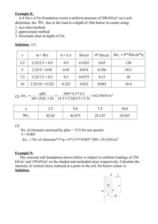
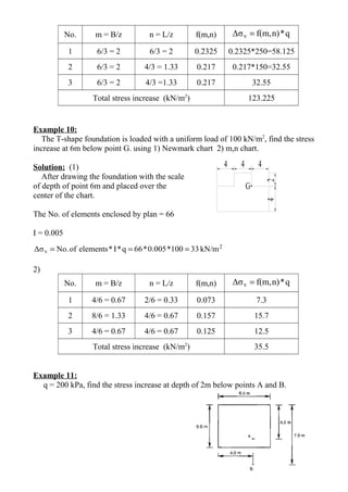
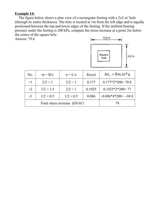
Three point loads and a uniform contact pressure on a circular foundation are used to calculate the vertical stress increase at various points below the foundations. The solutions involve determining shape factors from charts and formulas to calculate the stress contribution from each loading area. The stress increases are then summed to find the total vertical stress increase at the point of interest, which ranges from 0-186 kN/m^2 depending on the example.
![Example 1:
Three point loads, shown in figure, calculate the increase in vertical stress at point B.
Solution:
For the effect of p2
5/222
3
v
)z(r
z
2π
3p
Δσ
+
=
z = 3 m and r = 0
2
5/222
3
v t/m631.6
)3(0
3
2π
125*3
Δσ =
+
=
For the effect of p1
z= 3 m and m404yxr 2222
=+=+=
2
5/222
3
v t/m619.0
)3(4
3
2π
150*3
Δσ =
+
=
2
totalv t/m869.7619.0*2631.6Δσ =+=∴
Example 2:
For the point A, shown in figure below calculate the increase of vertical stress due to
the two line loads.
Solution:
592.1
]1)2/2[(π2
20*2
]1πz[(x/z)
2q
Δσ
2222
1
v1 =
+
=
+
=
095.0
]1)2/6[(π2
30*2
]1πz[(x/z)
2q
Δσ
2222
2
v2 =
+
=
+
=
2
v2v1totalv kN/m1.6870.0951.592ΔσΔσΔσ =+=+=
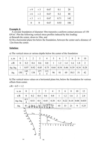
Example 3:
q = 200 kN/m2
, B = 6m, and z = 2m. Determine the vertical stress increase at ± 9, ± 6,
± 3, and 0.
Solution: a = B/2 = 6/2 = 3m
x x/a z/a q
Δσv
vΔσ
B
P1
=150 t P2
=125 t P3
=150 t
4 m4 m
3 m](https://image.slidesharecdn.com/examplesonstressdistribution-180320122017/85/Examples-on-stress-distribution-1-320.jpg)
![Example 1:
Three point loads, shown in figure, calculate the increase in vertical stress at point B.
Solution:
For the effect of p2
5/222
3
v
)z(r
z
2π
3p
Δσ
+
=
z = 3 m and r = 0
2
5/222
3
v t/m631.6
)3(0
3
2π
125*3
Δσ =
+
=
For the effect of p1
z= 3 m and m404yxr 2222
=+=+=
2
5/222
3
v t/m619.0
)3(4
3
2π
150*3
Δσ =
+
=
2
totalv t/m869.7619.0*2631.6Δσ =+=∴
Example 2:
For the point A, shown in figure below calculate the increase of vertical stress due to
the two line loads.
Solution:
592.1
]1)2/2[(π2
20*2
]1πz[(x/z)
2q
Δσ
2222
1
v1 =
+
=
+
=
095.0
]1)2/6[(π2
30*2
]1πz[(x/z)
2q
Δσ
2222
2
v2 =
+
=
+
=
2
v2v1totalv kN/m1.6870.0951.592ΔσΔσΔσ =+=+=
Example 3:
q = 200 kN/m2
, B = 6m, and z = 2m. Determine the vertical stress increase at ± 9, ± 6,
± 3, and 0.
Solution: a = B/2 = 6/2 = 3m
x x/a z/a q
Δσv
vΔσ
B
P1
=150 t P2
=125 t P3
=150 t
4 m4 m
3 m](https://image.slidesharecdn.com/examplesonstressdistribution-180320122017/75/Examples-on-stress-distribution-1-2048.jpg)
![Example 5:
The plan of a rectangular foundation shown below transmits a uniform contact
pressure of 120 kN/m2
. Determine the vertical stress induced by this loading: (a) at a
depth of 10m below point A, and (b) at a depth of 5m below B.
Solution:
(a) Consider four rectangles (1, 2, 3, 4) each with a corner at A: the vertical stress
below point A is the sum of the stresses induced by each rectangle.
v4v3v2v1(A)v ΔσΔσΔσΔσΔσ +++=
]n)f(m,n)f(m,n)f(m,n)[f(m,q 4321 +++=
Rectangle m = B/z n = L/z F(m,n)
1 10/10 = 1 5/10 = 0.5 0.12
2 10/10 = 1 20/10 = 2 0.2
3 5/10 = 0.5 20/10 = 2 0.135
4 5/10 = 0.5 5/10 = 0.5 0.084
2
(A)v kN/m64.680.084)0.1350.20.12(120Δσ =+++=](https://image.slidesharecdn.com/examplesonstressdistribution-180320122017/85/Examples-on-stress-distribution-3-320.jpg)
![(b) Consider four rectangles (1, 2, 3, 4) each with a corner at B.
]n)f(m,n)f(m,n)f(m,n)[f(m,qΔσ 4321(B)v +−−=
Rectangle m = B/z n = L/z f(m,n)
1 19/5 = 3.8 31/5 = 0.5 0.25
2 19/5 = 3.8 6/5 = 2 0.22
3 4/5 = 0.8 31/5 = 2 0.185
4 4/5 = 0.8 6/5 = 0.5 0.17
2
(B)v kN/m1.80.17)0.1850.220.25(120Δσ =+−−=
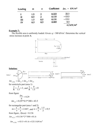
Example 6:
Plan view of a loading shown in the figure below. Find the vertical stress increase at a
depth of 3m below point A.
Solution:](https://image.slidesharecdn.com/examplesonstressdistribution-180320122017/85/Examples-on-stress-distribution-4-320.jpg)


![Geotechnical Engineering-II [Lec #7A: Boussinesq Method]](https://cdn.slidesharecdn.com/ss_thumbnails/7a-181020124807-thumbnail.jpg?width=640&height=640&fit=bounds)

![Geotechnical Engineering-II [Lec #25: Coulomb EP Theory - Numericals]](https://cdn.slidesharecdn.com/ss_thumbnails/25-181123050611-thumbnail.jpg?width=640&height=640&fit=bounds)


![Geotechnical Engineering-II [Lec #28: Finite Slope Stability Analysis]](https://cdn.slidesharecdn.com/ss_thumbnails/28-181125070402-thumbnail.jpg?width=640&height=640&fit=bounds)