
Recommended
Recommended
More Related Content
What's hot
What's hot (20)
Similar to stress distribution in soils
Similar to stress distribution in soils (20)
Recently uploaded
Recently uploaded (20)
stress distribution in soils
- 1. CHAPTER 2 : STRESS DISTRIBUTION, COMPRESSIBILITY AND SETTLEMENT OF SOILS
- 2. At the end of this lecture/week, the students will be able to : LEARNING OUTCOMES Learning Outcomes : 1. Identify and discuss all parameters required to determine the increase in vertical stress below a foundation subjected to different types of loading. 2. Formulate and evaluate the relevant increase in vertical stress due to various types of loading and footing shapes. Coverage : Stress distribution; Increase in vertical stress due to different loadings.
- 3. At the end of this lecture/week, the students will be able to : LEARNING OUTCOMES Learning Outcomes : 1. Formulate and evaluate vertical stress due to rectangular laoding and use Bulbs of Pressure Coverage : Stress distribution due to rectangular footing; Bulbs of pressure chart
- 4. 2.1 Introduction 2.2 Contact Pressures 2.3 Methods of Estimating Stress Distribution 2.4 Types of Loading system 2.5 Stress Distribution due to Different Loads 2.6 Bulbs of Pressure Chart Stress Distribution, Compressibility and Settlement of Soils OUTLINE OF PRESENTATION 2A : Stress Distribution in Soils
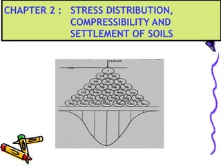
- 5. Introduction Stress Distribution in Soils Imposing load on the surface of the soil will create stresses within the mass. The loading transferred to the soil mass will be spread laterally with increasing depth from the point or area of application. With increasing depth, the area over which new stresses develop will increase but magnitude will decrease.
- 6. How the stress is perceived to be distributed from the surface a point in the soil mass. Stress Distribution in Soils
- 7. Factors affecting stress distribution : Size and shape of footing Load distribution Contact pressure – depends on the rigidity of footing and stiffness of foundation soil Modulus of Elasticity and Poisson’s ratio Position of rigid boundary Stress Distribution in Soils
- 8. Effect of Soil Type on Contact Pressure Contact pressure varies with the rigidity of foundation and the stiffness of soil beneath the foundation. Pressure Distribution Diagram Description Footing on hard soil or rock Due to high stiffness modulus, the load is distributed to a relatively small area since a high intensity of stress can develop. Stress Distribution in Soils
- 9. Effect of Soil Type on Contact Pressure Pressure Distribution Diagram Description Footing on stiff soil Load is distributed laterally which produces lower values of contact pressure Footing on soft soil The contact pressure on soil beneath the foundation is distributed almost uniformly. Stress Distribution in Soils
- 10. Effect of Footing Rigidity on Contact Pressure The distribution of pressure depending on footing rigidity Pressure Distribution Diagram Description Flexible footing Uniformly loaded footings of perfect flexibility will theoretically distribute a uniform contact pressure in compressible soil. Stress Distribution in Soils
- 11. Effect of Footing Rigidity on Contact Pressure Pressure Distribution Diagram Description Rigid footing on cohesive soil A higher contact pressures will be transmitted while settling uniformly. However, extremely high edge stresses cannot occur since the soil passes some of its load inwards and produces the arc-like distribution. Rigid footing on cohesionless soil Less contact pressure at the edges of footing but higher at mid-footing due to higher confining pressure. Uniform settlement will occur in this case. Stress Distribution in Soils
- 12. Boussinesq Stress Distribution 19 th.- century French mathematician assumed soil as homogeneous, isotropic (same properties in all directions) and elastic. publish solutions (1885) for stresses beneath a point load applied at the surface Stress Distribution in Soils
- 13. Following the footsteps of Boussinesq, other solutions were developed for both stresses and displacements relating to different types of loading, layers of thickness, multi-layered masses and internally loaded masses: Ahlvin and Ulery, 1962 Giroud, 1970 Newmark, 1942 Poulos and Davis, 1974 and others…… Stress Distribution in Soils
- 14. Westergaard Stress Distribution more suitable for thin layers of stratified deposits assumed that thin layers of a homogeneous and anisotropic material sandwiched between closely spaced, infinitely thin sheets of rigid material. permit compression but no lateral deformation formula different from Boussinesq. Stress Distribution in Soils
- 15. Methods of Estimating Stress Distribution Boussinesq’s method Westergaard’s method Newmark’s chart Bulbs of Pressure chart Stress Distribution in Soils
- 16. Types of Loading Point load based on Boussinesq based on Westergaard Line load Triangular load Strip load Uniformly loaded rectangular area Uniformly loaded circular area Stress Distribution in Soils
- 17. Load Distribution Stress Distribution in Soils
- 18. 2.1 Stresses due to a point load 2/5 2P 2 )/(1 1 2 3 I z P zr where IPz
- 19. Variation of stress due to a point load (a)Variation with depth
- 20. Variation of stress due to a point load (b) Variation with radial offset (r)
- 21. Table 2.1: Influence factors (Ip) for vertical stress due to a point load (P)
- 22. Ex. 1 : Stresses due to a Vertical Point Load Four column loads of 980 kN, 800 kN, 550 kN and 700 kN respectively are located at the corners of a square of 4 m side on the surface of a soil mass. A culvert passes diagonally across the square, directly under the 980kN and 550kN load, and a depth ( to its top) of 4 m. Calculate the vertical stress imposed on the culvert under the 980 kN load by using i) formula for the influence factor is IP = 3 1 5/2 2 1 + (r/z)2 ii) influence factor (IP) table. 550kN800kN 700kN 980kN 4m 4m
- 23. 2.2 Stresses due to the line load 222 2 Q )( 2z I z Q zx where IQz
- 24. Horizontal thrust on a rigid structure due to a line load
- 25. Table 2.2: Influence factors (IL) for vertical stress due to a line load (Q)
- 26. Stresses due to a Long Line Load Ex. 2 : Figure below shows two line loads and a point load acting at the ground surface. Determine the increase in vertical stress at point A, which is located at a depth of 1.5 m. Q2 = 10 kN/m Q1 = 5 kN/m P = 30 kN 2 m A z = 1.5 m 3 m 2 m
- 27. Stresses due to a Long Line Load Solution: 2 mkN0.902 012006508250 5143 51 2 303 514 51102 512 51152 2 5 222 3 222 3 222 3 ... . . . . . . zr z 2π 3P zxπ z2Q zxπ z2Q ΔσΔσΔσΔσ 2 5 22 3 222 2 3 2 222 1 3 1 3z2z1zz
- 28. 2.3 Stresses due to a uniform strip load z = qIs
- 29. Influence factors (Is) for vertical stress due to a strip load
- 30. Stresses Due to a Strip Load Three parallel strip foundation, each 1.8 m wide and 3.6 m apart centre to centre are founded at 1.2 m depth transmit contact pressures of 240 kPa, 180 kPa and 200 kPa respectively. Using the table of influence factor, Is , calculate the intensity of vertical stresses due to combined load beneath the centre of each footing at a depth of 3.0 m from the ground surface. 240kPa 180kPa 200kPa 3.6m 3.6m 3m 1.2m A CB Example 3
- 31. Stresses Due to a Strip Load Solution:
- 32. 2.4 Stresses due to a triangular load z = qIs
- 33. Influence factors (IT) for vertical stress due to a triangular strip load
- 34. Influence factors (IR) for vertical stress under one corner of a uniformly loaded rectangular area.
- 35. Triangular Strip Load Distribution Example 4 z CL A 3 m 10 m 3 m 5 m B AC 60 kN/m
- 36. SOLUTION: z = 5 m Vertical start point A. Is (kN/m2 ) Center (B) 0.48 28.8 Right slope (A) 0.172 10.32 Left slope (C) 0 0 TOTAL 39.12 b z b x qI sz 1 5 5 1 5 5 c z c x 67.1 3 5 1 3 3 67.1 3 5 33.4 3 13
- 37. • For a uniformly loaded circular areas, e.g. raft foundations, tank bases, etc., the basic Boussinesq expressions are integrated over the area. • An exact solution can be found for the increase in vertical stress under the centre, but for points offset from the centre an approximate method has to be used. 2.5 Stresses due to a uniformly loaded circular area
- 38. Stresses Due to a Uniformly Loaded Circular Area a) Stress beneath centre of circle b) General vertical stress case Example 5 : See worked example 6.4 --- Page 199 (Text book) z = qIc =q (A+B) Parameters = r/a & z/a r r z R z r aa
- 39. Influence factors (A and B) for vertical stress due to a uniformly loaded circular area.
- 40. • Most widely used in soil engineering design. • Component stress can be obtained by integrating the Boussinesq expressions L B z ∆z = q IR Ex. 6 : See worked example 6.5 --- Page 200 (Text book) 2.6 Stresses due to a uniformly loaded rectangular area
- 41. Fadum’s Chart Take note that the values of m ( =L/z) and n ( =B/z) are interchangeable !!
- 42. 2.7 Pressure bulbs for vertical stress (a) Circular foundation (b) Strip foundation
- 43. Pressure bulbs indicating depth to which soil is significantly stressed
- 44. References 1. Roy Whitlow, “Basic Soil Mechanics”, 4th Edition 2001, Prentice Hall 1 David F. McCarthy, “Essentials of Soil Mechanics and Foundations”, 5th Edition, 1998, Prentice Hall 2. Braja M. Das, “Principles of Geotechnical Engineering”, 4th Edition, 1998, PWS Publishing Company 3. G. N. Smith and Ian G. N. Smith, “Basic Soil Mechanics”, 7th Edition, 2000, Blackwell Science Stress Distribution in Soils Text