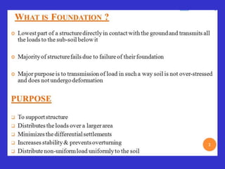
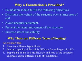
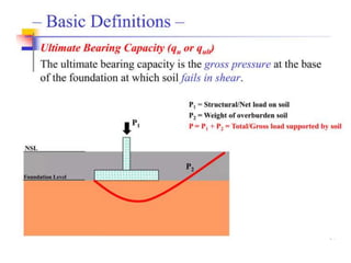
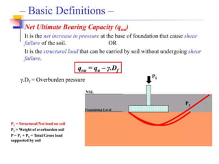
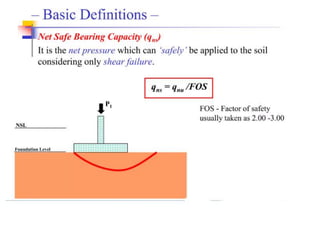
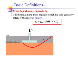
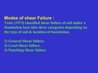
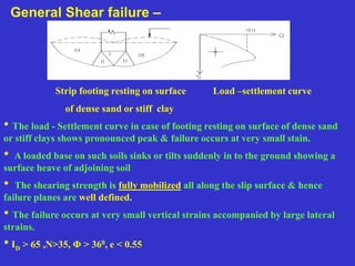
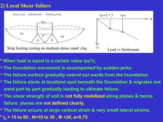
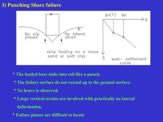
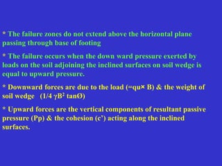
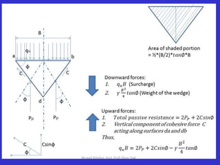
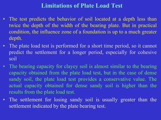
This document provides information on shallow foundations, including raft foundations. It discusses the bearing capacity of shallow foundations and factors that influence it, such as soil type, water table level, and loading conditions. Equations for calculating ultimate bearing capacity are presented, including Terzaghi's bearing capacity equation. The document also covers settlement of foundations, differential settlement, and allowable settlement values.

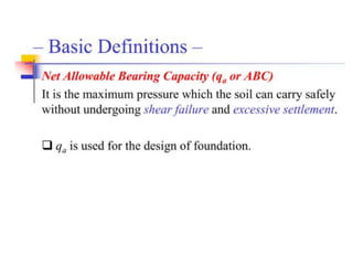
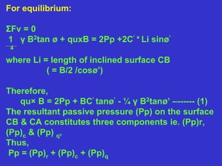
![qu× B= 2[ (Pp)r +(Pp)c +(Pp)q ]+ Bc’tanø’-¼ γ B2 tanø’
Substituting; 2 (Pp)r - ¼rB2tanø1 = B × ½ γ BNr
2 (Pp)q = B × γ D Nq
& 2 (Pp)c + Bc1 tanø1 = B × C1 Nc;
We get,
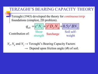
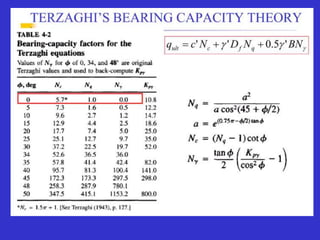
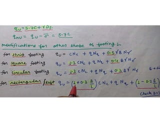
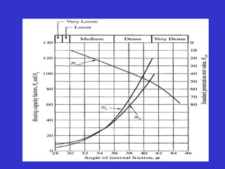
qu = C’Nc + γ Df Nq + 0.5 γ B N γ
This is Terzaghi’s Bearing capacity equation for
determining ultimate bearing capacity of strip footing.
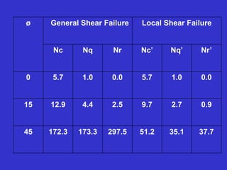
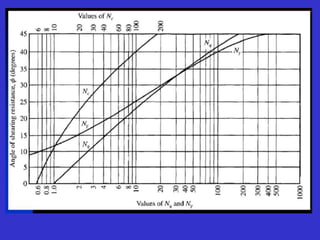
Where Nc, Nq & Nr are Terzaghi’s bearing capacity
factors & depends on angle of shearing resistance (ø)](https://image.slidesharecdn.com/bearingcapasityofsoil-230820112413-8ffded6d/85/BEARING-CAPASITY-OFSOIL-pptx-36-320.jpg)
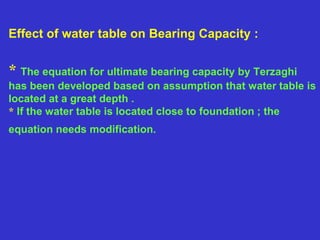
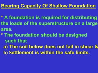
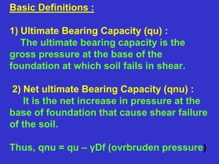
![Thus,
qu = c’Nc + [γsub Df +(γ - γsub )Dw] Nq + 0.5 γsub BNr
When, Dw =0
qu =c’Nc + γsub Nc + 0.5 γsub BNr
& when x = 0
qu = c’Nc + γ Df Nq + 0.5 γsub BNr](https://image.slidesharecdn.com/bearingcapasityofsoil-230820112413-8ffded6d/85/BEARING-CAPASITY-OFSOIL-pptx-45-320.jpg)
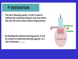
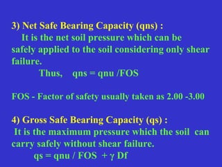
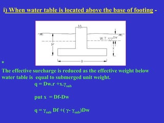
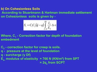
![Elastic settlement of foundation :
a) On Cohesive soils
According to schleicher, the vertical settlement
under uniformly distributed flexible area is,
Si = q B 1- μ2/Es I
where
q -uniformly distributed load.
B - characteristic length of loaded area,
Es - modulus of elasticity of the soil.
μ - poisson's ratio.
I - influence factor which dependent upon
elastic properties of base & shape at base.
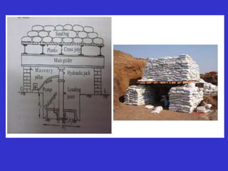
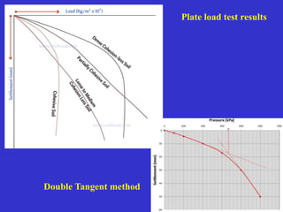
Alternatively, the value of [1- μ2/Es] I can be
determined from the plate load test.](https://image.slidesharecdn.com/bearingcapasityofsoil-230820112413-8ffded6d/85/BEARING-CAPASITY-OFSOIL-pptx-67-320.jpg)


![Geotechnical Engineering-II [Lec #13: Elastic Settlements]](https://cdn.slidesharecdn.com/ss_thumbnails/13-181020124852-thumbnail.jpg?width=640&height=640&fit=bounds)


![Geotechnical Engineering-II [Lec #17: Bearing Capacity of Soil]](https://cdn.slidesharecdn.com/ss_thumbnails/17-181123045836-thumbnail.jpg?width=640&height=640&fit=bounds)


![[LN], [Chapter3.1], Foundation Eng'g-1, Bearing Capacity of Shallow Foundatio...](https://cdn.slidesharecdn.com/ss_thumbnails/lnchapter3-251229124520-79d90b38-thumbnail.jpg?width=640&height=640&fit=bounds)


