Optical band gap measurement by diffuse reflectance spectroscopy (drs)Sajjad Ullah
Introduction to Optical band gap measurement
by electronic spectroscopy and diffuse reflectance spectroscopy (DRS) with comparison of the results obtained suing different equation and measurement techniques.
The role of scattering in extinction of light as it passes through media is briefly discussed.
Basic operating principle and instrumentation of photo-luminescence technique. Brief description about interpretation of a photo-luminescence spectrum. Applications, advantages and disadvantages of photo-luminescence.
Electrical properties of materialsElectrical properties of materialsElectrical properties of materialsElectrical properties of materialsElectrical properties of materialsElectrical properties of materialsElectrical properties of materialsElectrical properties of materialsElectrical properties of materialsElectrical properties of materialsElectrical properties of materialsElectrical properties of materialsElectrical properties of materialsElectrical properties of materialsElectrical properties of materialsElectrical properties of materialsElectrical properties of materialsElectrical properties of materialsElectrical properties of materialsElectrical properties of materialsElectrical properties of materialsElectrical properties of materialsElectrical properties of materialsElectrical properties of materialsElectrical properties of materialsElectrical properties of materialsElectrical properties of materialsElectrical properties of materialsElectrical properties of materialsElectrical properties of materialsElectrical properties of materialsElectrical properties of materialsElectrical properties of materialsElectrical properties of materialsElectrical properties of materialsElectrical properties of materialsElectrical properties of materialsElectrical properties of materialsElectrical properties of materialsElectrical properties of materialsElectrical properties of materialsElectrical properties of materialsElectrical properties of materials
Uv visible spectroscopy with InstrumentationSHIVANEE VYAS
It is the branch of science that deals with the study of the interaction of matter with light.
OR
It is the branch of science that deals with the study of the interaction of electromagnetic radiation with matter.
Electromagnetic radiation is energy that is propagated through free space or through a material medium in the form of electromagnetic waves, such as radio waves, visible light, and gamma rays, etc. Electromagnetic waves consist of discrete packages of energy which are called as photons.
A complete presentation on solar cells.
It includes working of solar cells,solar cell Models, parameters,Applications,solar energy harvesting,Generation wise comparison of solar cells,Kitchen made solar cells.This presentation can be a wild card entry to the arena of solar cells.
UV spectroscopy, Electronic transitions, law of UV, Deviations of UV, chromop...Rajesh Singh
This PowerPoint Presentation includes the principle, electronic transitions, application, chromophore, Auxochrome, Deviations and instrumentation of UV- Visible Spectrophotometer. It covers beer-lambert low and its quantitative applications. It also includes the qualitative applications in different fields of study. Presented by Rajesh Singh in GLA University Mathura.
For Education only!!!!
ວັດຖຸດິບທີ່ໃຊ້ໃນການການຜະລິດຜະລິດຕະພັນເຊລາມິກ
ວັດຖຸດິບປະເພດທີ່ມີຄວາມໜຽວ
ການເກີດ ແລະ ຊະນິດຂອງດີນ (Ocurance and Tpye of Clays)
ວັດຖຸດິບປະເພດທິບໍມີຄວາມໜຽວ
ບົດຮຽນຂ້າງເທິງນີ້ນຳໃຊ້ເຂົ້າໃນການຮຽນຮູ້ຂອງນັກສຶກສາທີ່ຕ້ອງການຢາກເຂົ້າໃນການເຄື່ອນທີ່ໃນທາງຟີຊິກ ແລະ ການແຕກຄວາມແຮງໃນການເຄື່ອນທີ່ວັດຖຸໃນແຕ່ລະກໍລະນີ. ການເຄື່ອນທີ່ໃນ 1 ມິຕິເປັນການເຄື່ອນທີ່ອັນເນື່ອງຈາກການປ່ຽນຕຳແໜ່ງ (Translation) ຈາກຕຳແໜ່ງໜຶ່ງໄປຫາອີກຕຳແໜ່ງໜື່ງໃນແນວພຽງ ຫຼື ແນວຕັ້ງ ພຽງແນວດຽວ ບໍ່ລວມການເຄື່ອນທີ່ອັນເນື່ອງຈາກການປີ່ນ ຫຼື ການເຄື່ອນທີ່ໃນແນວໂຄ້ງ ເຊິ່ງນັ້ນເປັນການເຄື່ອທີ່ 2 ມິຕິ.
A force is a push or pull upon an object resulting from the object's interaction with another object. Whenever there is an interaction between two objects, there is a force upon each of the objects. When the interaction ceases, the two objects no longer experience the force. Forces only exist as a result of an interaction.
We all have good and bad thoughts from time to time and situation to situation. We are bombarded daily with spiraling thoughts(both negative and positive) creating all-consuming feel , making us difficult to manage with associated suffering. Good thoughts are like our Mob Signal (Positive thought) amidst noise(negative thought) in the atmosphere. Negative thoughts like noise outweigh positive thoughts. These thoughts often create unwanted confusion, trouble, stress and frustration in our mind as well as chaos in our physical world. Negative thoughts are also known as “distorted thinking”.
Students, digital devices and success - Andreas Schleicher - 27 May 2024..pptxEduSkills OECD
Andreas Schleicher presents at the OECD webinar ‘Digital devices in schools: detrimental distraction or secret to success?’ on 27 May 2024. The presentation was based on findings from PISA 2022 results and the webinar helped launch the PISA in Focus ‘Managing screen time: How to protect and equip students against distraction’ https://www.oecd-ilibrary.org/education/managing-screen-time_7c225af4-en and the OECD Education Policy Perspective ‘Students, digital devices and success’ can be found here - https://oe.cd/il/5yV
Read| The latest issue of The Challenger is here! We are thrilled to announce that our school paper has qualified for the NATIONAL SCHOOLS PRESS CONFERENCE (NSPC) 2024. Thank you for your unwavering support and trust. Dive into the stories that made us stand out!
The Art Pastor's Guide to Sabbath | Steve ThomasonSteve Thomason
What is the purpose of the Sabbath Law in the Torah. It is interesting to compare how the context of the law shifts from Exodus to Deuteronomy. Who gets to rest, and why?
Model Attribute Check Company Auto PropertyCeline George
In Odoo, the multi-company feature allows you to manage multiple companies within a single Odoo database instance. Each company can have its own configurations while still sharing common resources such as products, customers, and suppliers.
2024.06.01 Introducing a competency framework for languag learning materials ...Sandy Millin
http://sandymillin.wordpress.com/iateflwebinar2024
Published classroom materials form the basis of syllabuses, drive teacher professional development, and have a potentially huge influence on learners, teachers and education systems. All teachers also create their own materials, whether a few sentences on a blackboard, a highly-structured fully-realised online course, or anything in between. Despite this, the knowledge and skills needed to create effective language learning materials are rarely part of teacher training, and are mostly learnt by trial and error.
Knowledge and skills frameworks, generally called competency frameworks, for ELT teachers, trainers and managers have existed for a few years now. However, until I created one for my MA dissertation, there wasn’t one drawing together what we need to know and do to be able to effectively produce language learning materials.
This webinar will introduce you to my framework, highlighting the key competencies I identified from my research. It will also show how anybody involved in language teaching (any language, not just English!), teacher training, managing schools or developing language learning materials can benefit from using the framework.
How to Create Map Views in the Odoo 17 ERPCeline George
The map views are useful for providing a geographical representation of data. They allow users to visualize and analyze the data in a more intuitive manner.
Unit 8 - Information and Communication Technology (Paper I).pdfThiyagu K
This slides describes the basic concepts of ICT, basics of Email, Emerging Technology and Digital Initiatives in Education. This presentations aligns with the UGC Paper I syllabus.
How to Make a Field invisible in Odoo 17Celine George
It is possible to hide or invisible some fields in odoo. Commonly using “invisible” attribute in the field definition to invisible the fields. This slide will show how to make a field invisible in odoo 17.
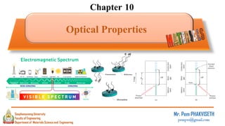
1. Chapter 10
Optical Properties
Mr. Pem PHAKVISETH
pempvs@gmail.com
Department of Materials Science and Engineering
Souphanouvong University
Faculty of Engineering
1
2. 10.1 Light and the Electromagnetic Radiation
Optical = “operating in or employing in the visible part of the electromagnetic
spectrum” or “ relating to sight, especially in relation to the action of light”.
Light is the form of energy detected by eye, and at ordinary scales can be treated as a
wave . Light wave are part of the electromagnetic spectrum, ranging continuously from
very long radio waves to high energy cosmic rays.
2
3. 3
00
1
=c
All electromagnetic radiation traverses a vacuum at the same velocity, namely, 3×10⁸m/s.
This velocity, c, is related to the electric permittivity of vacuum 𝜀0 and the magnetic
permeability of a vacuum 0 through
c v=
‒ : Wavelength in meters per cycle
‒ : Frequency in Hertz (cycles/sec)
• The Wavelength and Frequency of
EM waves are related thru c
• EM radiation has a Wave ↔ Particle Duality
• The Energy, E, of a Light Particle
( ) chE == h
‒ Where h : Planck’s Constant (6.63x10⁻³⁴ J-s)
‒ h is the PHOTON Energy
6. 6
10.2 Refraction
• When a ray of light passes from air to water its speed changes.
Due to this there is a change in direction of ray.
• The change of direction suffered by a ray of light as it passes
obliquely from one optical medium to another optical medium
with different optical densities is known as refraction.
• Whenever a ray of light is incident on a surface separating two
media, a small fraction of the light always gets reflected.
• Refraction can make an object appear to be in different
position.
7. 7
v
Or
MatlinLightofSpdVacuuminLightofSpd
c
n
n
=
=
▪Now the relations for v and c
1v =
• Where ε and µ are respectively the Permittivity
and Permeability of the Material
▪Now Recall
001 =c
▪ Thus n
rr
c
n
===
00
v
▪ Most Materials are NOT magnetic → µr 1
• So
• Ex. Germanium
rn
▪ When light changes from space to air to water, it slows down. This changes the path
it takes. That’s refraction.
▪ The refractive index is the ratio of the velocity of light in space to the velocity inside a
different material.
❑ Define the INDEX of REFRACTION, n
2
15.76n −
•n = 3.91
16.0r
8. 8
• The slowing of light in a Non-Vacuum Medium Results in Refraction, or Bending of
the light Path
▪ Light Refracts per Snell’s Law :
2211 sinsin nn =
Incident
ray
normal
Angle of Incidence
Angle of Refraction
Refracted ray
9. 9
10.3 Absorption, Transmission, Reflection
• Consider EM Radiation with Intensity I0 (in W/m2)
Impinging on a Solid
• The EM-Solid interaction Alters the incident
Beam by 3 possible Phenomena
• The EM Beam can be
• Reflected
• Absorbed
• Transmitted
10. 10
▪ An Energy Balance on the Solid:
• E-in = E-reflected + E-absorbed + E-transmitted
TAR IIII ++=0
•Now Divide E-Balance equation by I0
TAR ++=1
•Where:
–R REFLECTANCE (IR/I0)
–A ABSORBANCE (IA/I0)
–T TRANSMITTANCE (IT/I0)
0I
RI
TI
AI
11. 11
1.Transparent Materials 2.Translucent Materials 3.Opaque Materials
Classification of Optical Materials
•Opaque →
- T = 0
•Transparent →
– T >> A+R
– Light Not Scattered
• Translucent→
–T > A+R
–Light Scattered
12. 12
• Metals Interact with Light Thru QUANTIZED Photon Absorption by Electrons
▪ Metals have Very Closely
Spaced e- Energy Levels
Metals – Optical Absorption
•Thus Almost ALL incident
Photons are ABSORBED
within about 100 nm of the
surface
• Unfilled electron state are adjacent to filled states
• Near-surface electrons absorb visible light
13. 13
• The Absorbed Energy is ReEmitted by e- “falling” back to Lower Energy states
▪ Since Metals have Very
Closely Spaced e- Energy
Levels The Light is emitted
at many ’s
• Thus Outgoing Light Looks About the Same
as Incoming Light → High Reflectance
Metals – Optical Reflection
14. 14
• The reflectivity R represents the fraction of the
incident light that is reflected at the interface,
• If the light is normal (or perpendicular) to the
interface, then.
• When light is transmitted from a vacuum or air into a solid
s, then
Reflection
Optical Properties – Non-Metals
15. 15
• Example: For Diamond n = 2.41
• Reflection losses for lenses and other optical instruments are
minimized significantly by coating the reflecting surface with very
thin layers of dielectric materials such as magnesium fluoride
(MgF2).
𝑅 =
2.41 − 1
2.41 − 1
2
= 0.17
0.17% of light is reflected
16. 16
• In The Case of Materials with “Forbidden” Gaps in the Band Structure, Absorption Occurs only if h>Egap
incident photon
energy h
Energy of electron
filled states
unfilled states
Egap
Io
blue light: h = 3.1 eV
red light: h = 1.7 eV
Absorption
• The Material Color Depends on the
Width of the BandGap
▪For These
Materials there is Very
little ReEmission
17. 17
Color Cases – BandGap Matls
• Egap < 1.8 eV
• ALL Visible Light Absorbed; Solid Appears
Gray or Black in Color
• e.g., Si with Egap = 1.1 eV
• Egap > 3.1 eV
• NO Visible Light Absorbed; Solid Appears Clear and Transmissive
• e.g., Diamond Egap = 5.45 eV, SiO2 Egap = 8-9 eV
• 1.8 eV < Egap < 3.1 eV
• Some Light is absorbed and Material has a color
18. 18
NonMetal Colors
• Color determined by the sum of
frequencies
• transmitted light
• re-emitted light from electron
transitions
• e.g., Cadmium Sulfide (CdS)
• Egap = 2.4eV
• Absorbs higher energy visible light
(blue, violet),
▪ CdS
• Red/yellow/orange is
transmitted and gives it
this color
19. 19
Light Absorption/Reflection
• Amount of NON-Reflected Light Absorbed by a Materials
• For normally incident light passing into a solid having an
index of refraction n:
−
= e0IIT
= absorption coefficient, cm-1
= sample thickness, cm
= NonReflected incident light intensity
= transmitted light intensity
0I
TI
20. 20
Total Transmission
• Combining External and Internal Reflection, along with Beer’s Absorption
Yields the TOTAL Transmission Equation
( ) −
−= eRIIT
2
0 1
The transmission of light through a transparent medium for which there
is reflection at front and back faces, as well as absorption within the medium
21. 21
Total-T Example
• For the Situation at Right Determine the
thickness, d77, that will produce a total
Transmittance of 77%
• From Tab 21.1 Find Pyrex ns = 1.47
• Next find R using Equation (21.13)
13 mm
0I 086.0 I
QuartzPyrex
23 mm
%621.3
147.1
147.1
1
1
22
=
+
−
=
+
−
=
R
n
n
R
s
s
22. 22
• Recall total Transmission Eq
• Now Solve for β
13 mm
0I 086.0 I
QuartzPyrex
23 mm
( ) −
−= eRIIT
2
0 1
( )
2
0 1
TI
e
I R
−
=
−
( )
−=
−
2
0 1
ln
RI
IT
( )
−
−= 2
0
1
ln
R
IIT
• Thus
• Solving Total-T Eqn for the
length
• Then d77
( )
meter350.3
23
03621.01
86.0
ln 2
=
−
−=
mm
( )
−
−= 2
0
1
ln
R
IIT
( )
mm0.56
mm
00335.0
03621.01
77.0
ln
77
277
=
−
−=
d
d
23. 23
10.4 Luminescence
• With luminescence, energy is absorbed as a consequence of electron excitations, which
is subsequently reemitted as visible light. When light is reemitted in less than a second
after excitation, the phenomenon is called fluorescence. For longer reemission times,
the term phosphorescence is used.
• Electroluminescence is the phenomenon whereby light is emitted as a result of
electron–hole recombination events that are induced in a forward-biased diode
• The device that experiences electroluminescence is the light-emitting diode (LED).
24. 24
• Based on EM Induced e− excitation, and then Relaxation with Broad-Spectrum h Emission
▪ e.g.
fluorescent
lamps
25. 25
10.5 Optical Fibers
• Fiber optic (or "optical fiber") refers to the medium and the technology associated
with the transmission of information as light impulses along with a glass or plastic
wire or fiber. Fiber optic wire carries much more information than conventional
copper wire.
• Most telephone company long-distance lines are now fiber optic.
• Optical fibers use light to send information through the optical medium.
• The light from an electromagnetic carrier wave that is modulated to carry information.
26. 26
Structure of Optical Fibers
• Glass Core – central tube of very thin size made
up of optically transparent dielectric medium and
carries the light form transmitter to receiver. The
core diameter can vary from about 5um to 100 um.
• Glass Cladding – outer optical material
surrounding the core having reflecting index lower
than core. It helps to keep the light within the core
throughout the phenomena of total internal
reflection.
• Plastic Covering– plastic coating that protects the
fiber made of silicon rubber. The typical diameter
of fiber after coating is 250-300 um.
27. 27
• When light (radiation) shines on a material, it may be:
-- reflected, absorbed and/or transmitted.
• Optical classification:
-- transparent, translucent, opaque
• Metals:
-- fine succession of energy states causes absorption and reflection.
• Non-Metals:
-- may have full (Egap < 1.8eV) , no (Egap > 3.1eV), or
partial absorption (1.8eV < Egap = 3.1eV).
-- color is determined by light wavelengths that are
transmitted or re-emitted from electron transitions.
-- color may be changed by adding impurities which
change the band gap magnitude (e.g., Ruby)
• Refraction:
-- speed of transmitted light varies among materials.
10.6 SUMMARY
28. 28
Thank you for your attention !!!
감사합니다 !!!
Department of Materials Science and Engineering
Souphanouvong University
Faculty of Engineering