OUTLINE OF THECHAPTER
HAWASSA UNIVERSITY
INISTITUTE OF TECHNOLOGY
DEPARTMENT OF COMPUTER SCIENCE
CHAPTER THREE
Intel 8086 PROCESSOR PROGRAMING
&
INSTRUCTION SETS
2.
Addresing mode
The8086 has about 117 different instructions with about 300
opcodes.
The 8086 instruction sets can contain no operand, single operand,
and two operand instructions.
The processor can access memory in different ways that are
collectively called addressing mode.
The addressing modes describe the types of operands and the way
they are accessed for executing an instruction.
The number of addressing modes is determined when the
microprocessor is designed and cannot be changed.
3.
8086 ADDRESSING MODES
The 8086 provides a total of seven distinct addressing modes:
1. Register addressing modes
2. Immediate addressing modes
3. Direct addressing modes
4. Register indirect addressing modes
5. Based relative addressing modes
6. Indexed relative addressing modes
7. Based indexed relative addressing modes
MOV instructions are used to explain addressing modes.
4.
8086 ADDRESSING MODES(CONT..)
A) REGISTER ADDRESSING MODE:
MOV REG1, REG2;
The register addressing mode involves the use of registers to hold the data to
be manipulated.
Memory is not accessed when this addressing mode is executed;
Relatively fast transfer since memory is not accessed.
Examples:
MOV BX, DX ; copy the contents of DX into BX
MOV ES, AX ; copy the contents of AX into ES
ADD AL, BH ; add the contents of BH to Contents of AL.
The size of reg1 and reg2 must be the same.
MOV CL, AX is illegal for instance.
5.
8086 ADDRESSING MODES(CONT..)
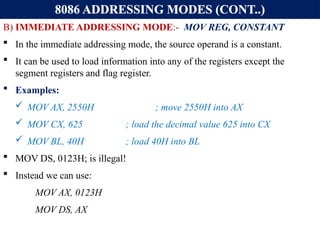
B) IMMEDIATE ADDRESSING MODE:- MOV REG, CONSTANT
In the immediate addressing mode, the source operand is a constant.
It can be used to load information into any of the registers except the
segment registers and flag register.
Examples:
MOV AX, 2550H ; move 2550H into AX
MOV CX, 625 ; load the decimal value 625 into CX
MOV BL, 40H ; load 40H into BL
MOV DS, 0123H; is illegal!
Instead we can use:
MOV AX, 0123H
MOV DS, AX
6.
8086 ADDRESSING MODES(CONT..)
C) DIRECT ADDRESSING MODE:
MOV REG, [constant] or MOV [constant], REG
Here constant is not operand but it is an offset or EA in memory of operand.
In the direct addressing mode the data is in some memory location(s) and the
address of the data in memory comes immediately after the instruction.
This address is the offset address and one can calculate the physical address
by shifting left the DS register and adding it to the offset as follows:
Example:
MOV DL, [2400H] ; move contents of DS: 2400H into DL
EXERCISE 3-1: Find the physical address of the memory location and its
contents after the execution of the following,
MOV AL, 99H
MOV [3518H], AL ;Assuming that DS = 1512H.
7.
Cont…
Direct addressingmode:
address of the data in memory comes immediately after the
instruction operand is a constant
The address is the offset address. The offset address is put in a
rectangular bracket
Ex: MOV DL,[2400] ; move contents of DS:2400H into DL
Physical address of DS:3518 => 15120+3518=18638H
The memory location 18638H will contain the value 99H
8.
8086 ADDRESSING MODES(CONT..)
D) REGISTER INDIRECT ADDRESSING MODE:
MOV REG1, [REG2] or MOV [REG2], REG1;
Here the address of the memory location where the operand resides is held
by a register, REG2.
REG1 can be any general purpose register and REG2 can be either of SI, DI,
or BX and they must be combined with DS in order to generate the 20-bit
physical address.
Example:
MOV AL, [BX] ; move contents of DS:BX into AL
MOV CL, [SI] ; move contents of DS:SI into CL
MOV [DI], AH ; move contents of AH into DS:DI
MOV DX, [BX] ; move contents of DS:BX into DL and
; contents of DS:BX+1 into DH
9.
8086 ADDRESSING MODES(CONT..)
Exercise:
Assume that DS = 1120H, SI = 2498H, and AX = 17FEH.
Show the contents of memory locations and its contents after the
execution of MOV [SI], AX.
Solution:
The contents of AX are moved into memory locations with logical address
DS: SI and DS: SI + 1;
Therefore, the physical address starts at:
PA = DS (shifted left) + SI = 13698H.
According to the little endian convention,
low address 13698H contains FEH, the low byte, and
high address 13699H will contain 17H, the high byte.
10.
8086 ADDRESSING MODES(CONT..)
E) BASED RELATIVE ADDRESSING MODE:
MOV REG1, [REG2] + CONST or
MOV [REG2] + CONST, REG1;
CONST is an 8-bit displacement value.
REG1 can be any general purpose register and REG2 can only be either of
BP or BX
In the based relative addressing mode, base registers BX and BP, as well as a
displacement value, are used to calculate what is called the effective address.
The default segments used for the calculation of the physical address (PA)
are DS for BX and SS for BP.
PA = DS*10H + BX + const ; EA = BX + const
PA = SS*10H + BP + const ; EA = BP + const
11.
8086 ADDRESSING MODES(CONT..)
EXAMPLES: Determine PA and EA
MOV CX, [BX]+10 ; move DS:BX + 10 and DS:BX+10+1 into CX.
PA = DS*10H + BX + 10, EA = BX + 10
MOV AL, [BP] + 5 ;
PA = SS*10H + BP + 5
EA = BP + 5
Alternative codings for MOV reg1, [reg2] + constant is
MOV reg1, [reg2 + constant] or
MOV reg1, const[reg2]
For instance, MOV CX, [BX]+10 is same as
MOV CX, [BX+10] or
MOV CX, 10[BX]
12.
8086 ADDRESSING MODES(CONT..)
F) INDEXED RELATIVE ADDRESSING MODE:
MOV REG1, [REG2] + CONST OR
MOV [REG2] + CONST, REG1;
The indexed relative addressing mode works the same as the based relative
addressing mode, except that registers DI and SI hold the offset address.
Constant is an 8-bit displacement value.
REG1 can be any general purpose register and REG2 can only be either of
DI or SI
PA = DS*10H + DI + const ; EA=DI + const or
PA = DS*10H + SI + const ; EA= SI + const
Examples:
MOV DX, [SI]+5 ; PA = DS (shifted left) + SI + 5
MOV CL, [DI]+20 ; PA = DS (shifted left) + DI + 20
13.
8086 ADDRESSING MODES(CONT..)
EXERCISE 3-3:
Assume that DS = 4500, SS = 2000, BX = 2100, SI = 1486, DI = 8500, BP =
7814, and AX = 2512. Show the exact physical memory location where AX is
stored in each of the following. All values are in hex.
a) MOV [BX]+20, AX
b) MOV [SI]+10, AX
c) MOV [DI]+4, AX
d) MOV [BP]+12, AX
Solution: In each case PA = segment register (shifted left) + offset register +
displacement.
a. DS:BX+20 ;location 47120 = (12) and 47121 =(25)
b. DS:SI+10 ;location 46496 = (12) and 46497 = (25)
c. DS:DI+4 ;location 4D504 = (12) and 4D505 = (25)
d. SS:BP+12 ;location 27826 = (12) and 27827 = (25)
14.
8086 ADDRESSING MODES(CONT..)
G) BASED INDEXED ADDRESSING MODE:
MOV REG1, [REG2][REG3] + CONST OR
MOV [REG2][REG3] + CONST, REG1;
In this mode, one base register and one index register are used.
REG1 can be any general purpose register and REG2 can only be either of DI or SI
and reg3 can only be either of BX or BP.
PA= DS*10H+BX+DI + const; EA=DI+BX+ const or PA=SS*10H+BP+SI+const
and EA= SI + BP + const
EXAMPLES:
MOV CL, [BX][DI]+8 ;PA = DS (shifted left) + BX + DI + 8
MOV CH, [BX][SI]+20 ;PA = DS (shifted left) + BX + SI + 20
MOV AH, [BP][SI]+29 ;PA = SS (shifted left) + BP + SI + 29
MOV AH, [BP][DI]+29 ;PA = SS (shifted left) + BP + DI + 29
Note that "MOV AX, [SI][DI]+displacement" is illegal.
15.
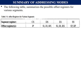
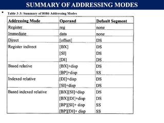
SUMMARY OF ADDRESSINGMODES
The following table, summarizes the possible offset registers for
various segments.
16.
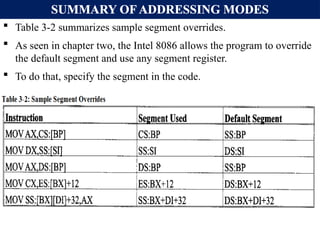
SUMMARY OF ADDRESSINGMODES
Table 3-2 summarizes sample segment overrides.
As seen in chapter two, the Intel 8086 allows the program to override
the default segment and use any segment register.
To do that, specify the segment in the code.
8086 ADDRESSING MODES(CONT..)
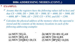
EXAMPLE:
Assume that the registers have the following values (all in hex) and
that CS =1000, DS = 2000, SS = 3000, SI = 4000, DI = 5000, BX
= 6080, BP = 7000, AX = 25FF, CX = 8791, and DX = 1299.
Calculate the physical address of the memory where the operand is
stored and the contents of the memory locations in each of the
following addressing examples
19.
Comparison of addressingmodes
Mode Algorithm Advantage Disadvantage
Register EA= R No memory
reference
Limited address
space
Immediate Operand =A No memory
reference
Limited operand
magnitude
Direct EA=A simple Limited address
space
Register Indirect EA=[R] Large address
space
Extra memory
reference
Displacement EA= A+[R] flexibility complexity
20.
Hu, Institute OfTechnology Department Of Electrical And Computer Engineering 20
Quiz-1
1. Show how the flag register is
affected by:
Mov BX, AAA9H
Add BX, 5557H
2. Assume that SS=4567H, DS =
1120H, ES=4567H, SI = 2498H, and
AX = 17FEH. Show the contents of
memory locations and its contents
after the execution of MOV [SI], AX.
21.
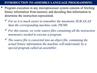
INTRODUCTION TO ASSEMBLYLANGUAGE PROGRAMMING
Program execution in any microprocessor system consists of fetching
binary information from memory and decoding that information to
determine the instruction represented.
For us it is much easier to remember the mnemonic SUB AX,AX
than the corresponding machine code 29C0H.
For this reason, we write source files containing all the instruction
mnemonics needed to execute a program.
The source file is converted into an object file, containing the
actual binary information the machine will understand, by a
special program called an assembler.
22.
INTRODUCTION TO ASSEMBLYLANGUAGE PROGRAMMING
An Assembly language program is :
A series of statements, or lines which is, either Assembly language
instructions, or Pseudo-instruction called Directives.
Directives (pseudo-instructions):
Give directions to the assembler about how it should translate the
Assembly language instructions into machine code.
Assembly language instructions consist of four fields:
[label:] mnemonic [operands] [;comment]
Brackets indicate that the field is optional, do not type in the brackets.
The comment field begins with a ";" and may be at the end of a line. The
assembler ignores comments.
Comments are optional, but highly recommended to make it easier to
read and understand the program.
23.
DIRECTIVES AND ASAMPLE PROGRAM
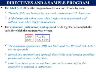
The label field allows the program to refer to a line of code by name.
The label field can be any character and cannot exceed 31 characters.
A label must end with a colon when it refers to an opcode and, end
without colon when it refer to directives.
The mnemonic (instruction) and operand fields together accomplish the
tasks for which the program was written.
The mnemonic opcodes are ADD and MOV, and "AL,BL" and "AX, 6764"
are the operands.
Instead of a mnemonic and operand, these fields could contain assembler
pseudo-instructions, or directives.
Directives do not generate machine code and are used only by the
assembler as opposed to instructions.
24.
DIRECTIVES AND ASAMPLE PROGRAM
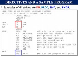
Examples of directives are DB, PROC, END, and ENDP.
25.
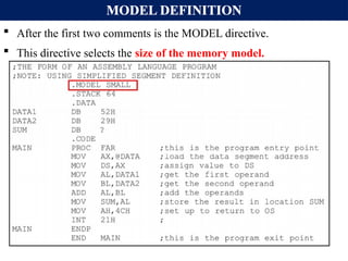
MODEL DEFINITION
Afterthe first two comments is the MODEL directive.
This directive selects the size of the memory model.
26.
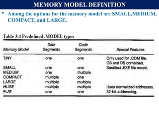
MEMORY MODEL DEFINITION
Among the options for the memory model are SMALL,MEDIUM,
COMPACT, and LARGE.
27.
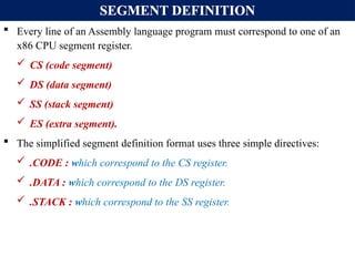
SEGMENT DEFINITION
Everyline of an Assembly language program must correspond to one of an
x86 CPU segment register.
CS (code segment)
DS (data segment)
SS (stack segment)
ES (extra segment).
The simplified segment definition format uses three simple directives:
.CODE : which correspond to the CS register.
.DATA : which correspond to the DS register.
.STACK : which correspond to the SS register.
28.
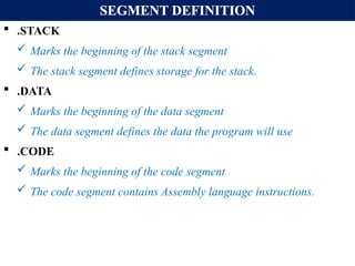
SEGMENT DEFINITION
.STACK
Marks the beginning of the stack segment
The stack segment defines storage for the stack.
.DATA
Marks the beginning of the data segment
The data segment defines the data the program will use
.CODE
Marks the beginning of the code segment
The code segment contains Assembly language instructions.
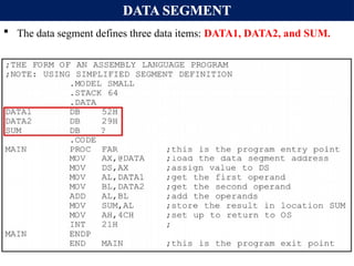
DATA SEGMENT
Thedata segment defines three data items: DATA1, DATA2, and SUM.
31.
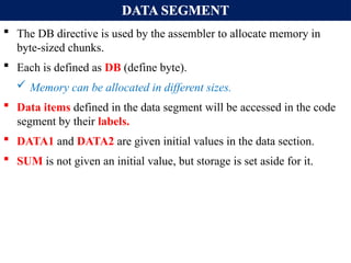
DATA SEGMENT
TheDB directive is used by the assembler to allocate memory in
byte-sized chunks.
Each is defined as DB (define byte).
Memory can be allocated in different sizes.
Data items defined in the data segment will be accessed in the code
segment by their labels.
DATA1 and DATA2 are given initial values in the data section.
SUM is not given an initial value, but storage is set aside for it.
32.
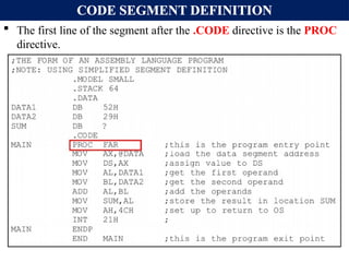
CODE SEGMENT DEFINITION
The first line of the segment after the .CODE directive is the PROC
directive.
33.
CODE SEGMENT DEFINITION
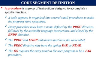
A procedure is a group of instructions designed to accomplish a
specific function.
A code segment is organized into several small procedures to make
the program more structured.
Every procedure must have a name defined by the PROC directive,
followed by the assembly language instructions, and closed by the
ENDP directive.
The PROC and ENDP statements must have the same label.
The PROC directive may have the option FAR or NEAR.
The OS requires the entry point to the user program to be a FAR
procedure.
34.
CODE SEGMENT DEFINITION
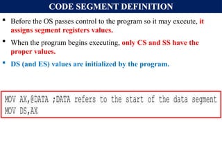
Before the OS passes control to the program so it may execute, it
assigns segment registers values.
When the program begins executing, only CS and SS have the
proper values.
DS (and ES) values are initialized by the program.
35.
CODE SEGMENT DEFINITION
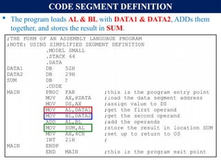
The program loads AL & BL with DATA1 & DATA2, ADDs them
together, and stores the result in SUM.
36.
CODE SEGMENT DEFINITION
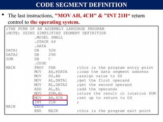
The last instructions, "MOV AH, 4CH" & "INT 21H“ return
control to the operating system.
37.
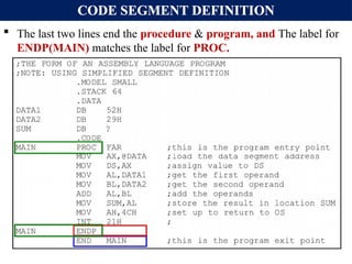
CODE SEGMENT DEFINITION
The last two lines end the procedure & program, and The label for
ENDP(MAIN) matches the label for PROC.
38.
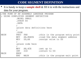
CODE SEGMENT DEFINITION
It is handy to keep a sample shell & fill it in with the instructions and
data for your program.
39.
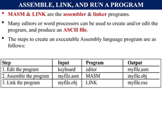
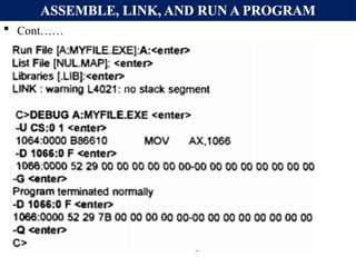
ASSEMBLE, LINK, ANDRUN A PROGRAM
MASM & LINK are the assembler & linker programs.
Many editors or word processors can be used to create and/or edit the
program, and produce an ASCII file.
The steps to create an executable Assembly language program are as
follows:
Introduction to AssemblyLanguage Programming
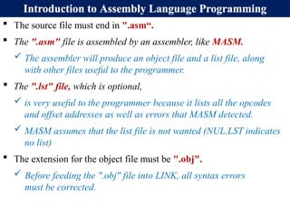
The source file must end in ".asm“.
The ".asm" file is assembled by an assembler, like MASM.
The assembler will produce an object file and a list file, along
with other files useful to the programmer.
The ".lst" file, which is optional,
is very useful to the programmer because it lists all the opcodes
and offset addresses as well as errors that MASM detected.
MASM assumes that the list file is not wanted (NUL.LST indicates
no list)
The extension for the object file must be ".obj".
Before feeding the ".obj" file into LINK, all syntax errors
must be corrected.
42.
ASSEMBLE, LINK, ANDRUN A PROGRAM
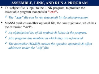
This object file is input to the LINK program, to produce the
executable program that ends in ".exe".
The ".exe" file can be run (executed) by the microprocessor.
MASM produces another optional file, the crossreference, which has
the extension ".crf".
An alphabetical list of all symbols & labels in the program.
Also program line numbers in which they are referenced.
The assembler (MASM) creates the opcodes, operands & offset
addresses under the ".obj" file.
43.
ASSEMBLE, LINK, ANDRUN A PROGRAM
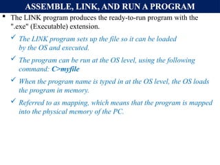
The LINK program produces the ready-to-run program with the
".exe" (Executable) extension.
The LINK program sets up the file so it can be loaded
by the OS and executed.
The program can be run at the OS level, using the following
command: C>myfile
When the program name is typed in at the OS level, the OS loads
the program in memory.
Referred to as mapping, which means that the program is mapped
into the physical memory of the PC.
44.
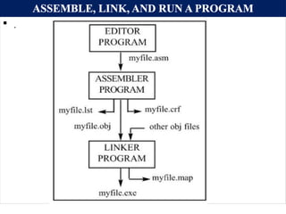
ASSEMBLE, LINK, ANDRUN A PROGRAM
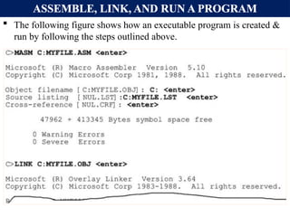
The following figure shows how an executable program is created &
run by following the steps outlined above.
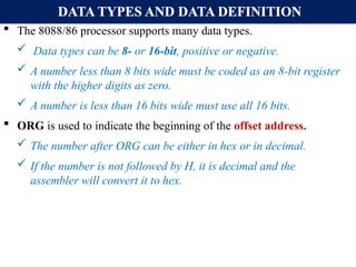
DATA TYPES ANDDATA DEFINITION
The 8088/86 processor supports many data types.
Data types can be 8- or 16-bit, positive or negative.
A number less than 8 bits wide must be coded as an 8-bit register
with the higher digits as zero.
A number is less than 16 bits wide must use all 16 bits.
ORG is used to indicate the beginning of the offset address.
The number after ORG can be either in hex or in decimal.
If the number is not followed by H, it is decimal and the
assembler will convert it to hex.
47.
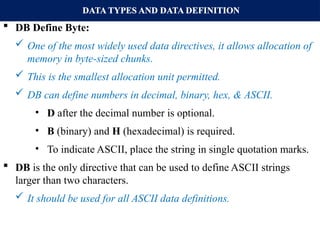
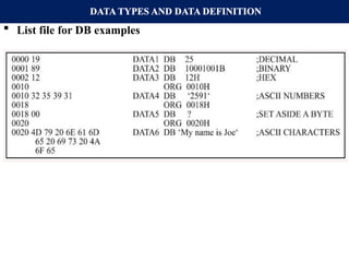
DATA TYPES ANDDATA DEFINITION
DB Define Byte:
One of the most widely used data directives, it allows allocation of
memory in byte-sized chunks.
This is the smallest allocation unit permitted.
DB can define numbers in decimal, binary, hex, & ASCII.
• D after the decimal number is optional.
• B (binary) and H (hexadecimal) is required.
• To indicate ASCII, place the string in single quotation marks.
DB is the only directive that can be used to define ASCII strings
larger than two characters.
It should be used for all ASCII data definitions.
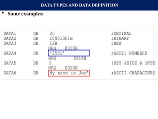
DATA TYPES ANDDATA DEFINITION
List file for DB examples
50.
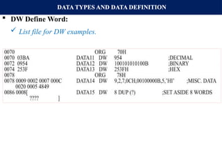
DATA TYPES ANDDATA DEFINITION
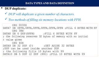
DUP duplicate:
DUP will duplicate a given number of characters.
Two methods of filling six memory locations with FFH.
51.
DATA TYPES ANDDATA DEFINITION
List file of DUP example:
52.
DATA TYPES ANDDATA DEFINITION
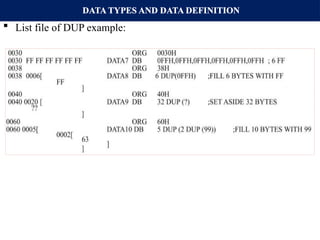
DW Define Word:
DW is used to allocate memory 2 bytes (one word) at a time:
53.
DATA TYPES ANDDATA DEFINITION
DW Define Word:
List file for DW examples.
54.
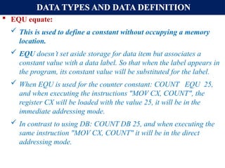
DATA TYPES ANDDATA DEFINITION
EQU equate:
This is used to define a constant without occupying a memory
location.
EQU doesn’t set aside storage for data item but associates a
constant value with a data label. So that when the label appears in
the program, its constant value will be substituted for the label.
When EQU is used for the counter constant: COUNT EQU 25,
and when executing the instructions "MOV CX, COUNT", the
register CX will be loaded with the value 25, it will be in the
immediate addressing mode.
In contrast to using DB: COUNT DB 25, and when executing the
same instruction "MOV CX, COUNT" it will be in the direct
addressing mode.
55.
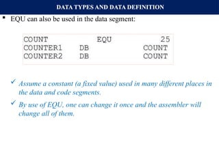
DATA TYPES ANDDATA DEFINITION
EQU can also be used in the data segment:
Assume a constant (a fixed value) used in many different places in
the data and code segments.
By use of EQU, one can change it once and the assembler will
change all of them.
56.
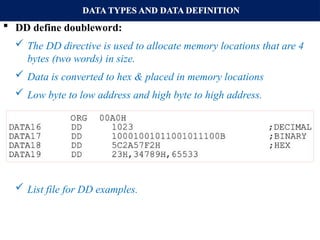
DATA TYPES ANDDATA DEFINITION
DD define doubleword:
The DD directive is used to allocate memory locations that are 4
bytes (two words) in size.
Data is converted to hex & placed in memory locations
Low byte to low address and high byte to high address.
List file for DD examples.
57.
DATA TYPES ANDDATA DEFINITION
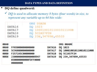
DQ define quadword:
DQ is used to allocate memory 8 bytes (four words) in size, to
represent any variable up to 64 bits wide:
List file for DQ examples.
58.
DATA TYPES ANDDATA DEFINITION
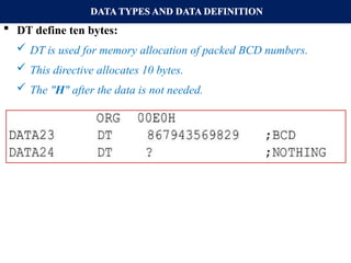
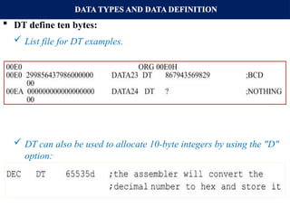
DT define ten bytes:
DT is used for memory allocation of packed BCD numbers.
This directive allocates 10 bytes.
The "H" after the data is not needed.
59.
DATA TYPES ANDDATA DEFINITION
DT define ten bytes:
List file for DT examples.
DT can also be used to allocate 10-byte integers by using the "D"
option:
60.
FULL SEGMENT DEFINITION
SEGMENT DEFINITION:
The SEGMENT and ENDS directives indicate the beginning &
ending of a segment, in this format:
The label, or name, must follow naming conventions and be
unique.
The [options] field gives important information to the assembler
for organizing the segment, but is not required.
The ENDS label must be the same label as in the SEGMENT
directive.
In full segment definition, the ".MODEL" directive is not used.
61.
FULL SEGMENT DEFINITION
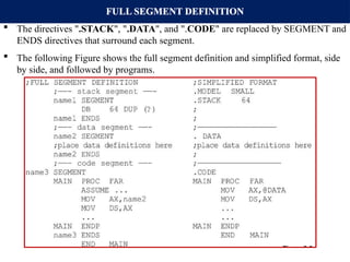
The directives ".STACK", ".DATA", and ".CODE" are replaced by SEGMENT and
ENDS directives that surround each segment.
The following Figure shows the full segment definition and simplified format, side
by side, and followed by programs.
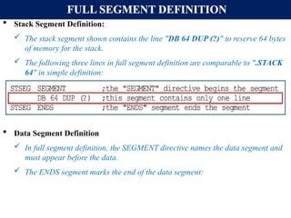
FULL SEGMENT DEFINITION
Stack Segment Definition:
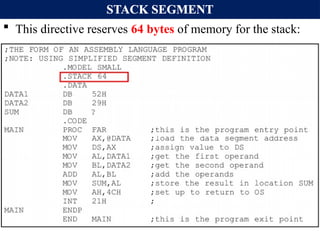
The stack segment shown contains the line "DB 64 DUP (?)" to reserve 64 bytes
of memory for the stack.
The following three lines in full segment definition are comparable to ".STACK
64" in simple definition:
Data Segment Definition
In full segment definition, the SEGMENT directive names the data segment and
must appear before the data.
The ENDS segment marks the end of the data segment:
65.
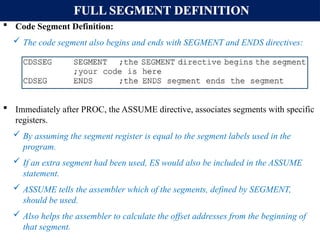
FULL SEGMENT DEFINITION
Code Segment Definition:
The code segment also begins and ends with SEGMENT and ENDS directives:
Immediately after PROC, the ASSUME directive, associates segments with specific
registers.
By assuming the segment register is equal to the segment labels used in the
program.
If an extra segment had been used, ES would also be included in the ASSUME
statement.
ASSUME tells the assembler which of the segments, defined by SEGMENT,
should be used.
Also helps the assembler to calculate the offset addresses from the beginning of
that segment.
66.
FULL SEGMENT DEFINITION
In "MOV AL, [BX] " the BX register is the offset of the data
segment.
On transfer of control from OS to the program, of the three segment
registers, only CS and SS have the proper values.
The DS value (and ES) must be initialized by the program
67.
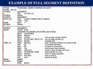
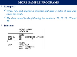
MORE SAMPLE PROGRAMS
Example1:
Write, run, and analyze a program that adds 5 bytes of data and
saves the result.
The data should be the following hex numbers: 25, 12, 15, 1F, and
2B.
Solution:
68.
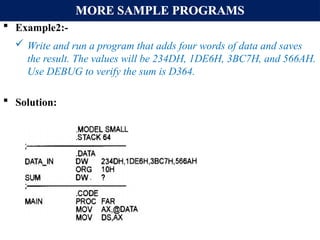
MORE SAMPLE PROGRAMS
Example2:-
Write and run a program that adds four words of data and saves
the result. The values will be 234DH, 1DE6H, 3BC7H, and 566AH.
Use DEBUG to verify the sum is D364.
Solution:
69.
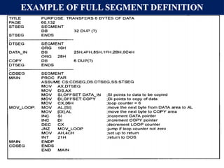
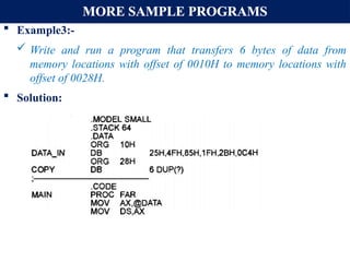
MORE SAMPLE PROGRAMS
Example3:-
Write and run a program that transfers 6 bytes of data from
memory locations with offset of 0010H to memory locations with
offset of 0028H.
Solution:
70.
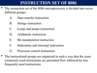
INSTRUCTION SET OF8086
The instruction set of the 8086 microprocessor is divided into seven
different groups:
A. Data transfer instruction
B. Strings instruction
C. Loops and jumps instruction
D. Arithmetic instruction
E. Bit manipulation instruction
F. Subroutine and interrupt instruction
G. Processor control instruction
The instructional groups are organized in such a way that the more
commonly used instructions are presented first, followed by less
frequently used instructions.
71.
DATA TRANSFER INSTRUCTIONS:
This group of instructions makes it possible to move (copy) data
around inside the processor and between the processor and its
memory.
A. MOV DESTINATION, SOURCE:
Transfer can be from register to register, register to memory or from
memory to register but not from memory to memory.
The source and destination must be of same type i.e. either both must
be byte or word.
In this instruction, the assembler will look at the size of the specified
register in the operand field to determine if the immediate data is a
1-, or 2-byte number.
MOV instruction does not affect any flags.
72.
DATA TRANSFER INSTRUCTIONS:
EXAMPLE: MOV AL, 30H
MOV AX, 30H
In the first instruction, the 30H is coded as a byte value because it is
being MOVed into AL.
In the second instruction, the 30H is coded as a word value because it
is being MOVed into AX.
This is clearly shown by the resulting code for both instructions.
MOV AL, 30H is coded as B0 30 and MOV AX, 30H is coded as B8
30 00.
Note that the second two bytes represent the byte-swapped value
0030H.
DATA TRANSFER INSTRUCTIONS:
Some times, For example, in MOV [SI], 0 the processor does not
know if the operand should be coded as a byte value, or as word
value.
For cases like this, we use BYTE PTR and WORD PTR directives
to indicate the size of data.
If you wish to MOV a byte value into memory, use:
MOV BYTE PTR [SI], 0
MOV WORD PTR [SI], 0
The byte ptr, and word ptr assembler directives stand for "byte
pointer," and "word pointer."
76.
Cont…
The INTInstruction
The INT instruction is the instruction which does the most work in
any assembler program.
What it does is it calls a DOS interrupt (like a function) to perform
a special task.
When one wants to read from the keyboard or disk or mouse, or
write to the screen, one uses an interrupt.
77.
Cont…
Each interruptthough, has a number of sub-
functions which select the individual task that
the function has to do
MOV AH,02
To select subfunction 2, move the appropriate number, 2, to AH
char display interupt code
MOV DL,"!"
In the interrupt list, it says that the character to output should be in
register DL. So we move the character to DL.
78.
Cont…
MOV AH,01
To select subfunction 1, accept input
MOV AH,09
To select subfunction 9, to display string
We can also use
Print “” statement to display strings
We have to include “emu8086.inc” to do so
79.
Cont…
MOV AH,02- Function to output a char
MOV DL,"!” - Character to output
INT 21h - Call the interrupt to output "!"
MOV AH,04Ch -Select exit function
MOV AL,00 -Return 0
INT 21h -Call the interrupt to exit
80.
Cont…
INT 21h
Finally when all the registers are set as required, we call the
interrupt.
81.
DATA TRANSFER INSTRUCTIONS(cont..)
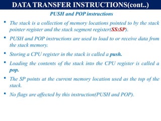
PUSHand POP instructions
The stack is a collection of memory locations pointed to by the stack
pointer register and the stack segment register(SS:SP).
PUSH and POP instructions are used to load to or receive data from
the stack memory.
Storing a CPU register in the stack is called a push.
Loading the contents of the stack into the CPU register is called a
pop.
The SP points at the current memory location used as the top of the
stack.
No flags are affected by this instruction(PUSH and POP).
82.
DATA TRANSFER INSTRUCTIONS(cont..)
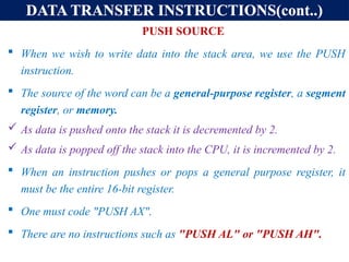
PUSHSOURCE
When we wish to write data into the stack area, we use the PUSH
instruction.
The source of the word can be a general-purpose register, a segment
register, or memory.
As data is pushed onto the stack it is decremented by 2.
As data is popped off the stack into the CPU, it is incremented by 2.
When an instruction pushes or pops a general purpose register, it
must be the entire 16-bit register.
One must code "PUSH AX".
There are no instructions such as "PUSH AL" or "PUSH AH".
83.
DATA TRANSFER INSTRUCTIONS(cont..)
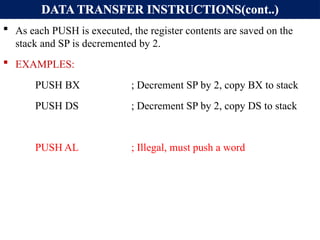
As each PUSH is executed, the register contents are saved on the
stack and SP is decremented by 2.
EXAMPLES:
PUSH BX ; Decrement SP by 2, copy BX to stack
PUSH DS ; Decrement SP by 2, copy DS to stack
PUSH AL ; Illegal, must push a word
84.
DATA TRANSFER INSTRUCTIONS(cont..)
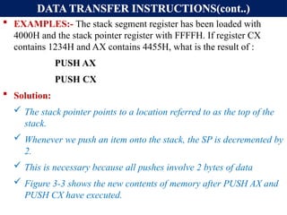
EXAMPLES:- The stack segment register has been loaded with
4000H and the stack pointer register with FFFFH. If register CX
contains 1234H and AX contains 4455H, what is the result of :
PUSH AX
PUSH CX
Solution:
The stack pointer points to a location referred to as the top of the
stack.
Whenever we push an item onto the stack, the SP is decremented by
2.
This is necessary because all pushes involve 2 bytes of data
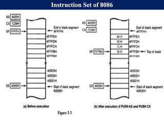
Figure 3-3 shows the new contents of memory after PUSH AX and
PUSH CX have executed.
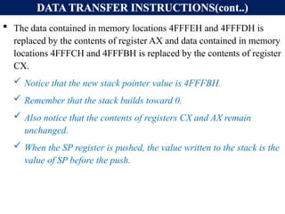
DATA TRANSFER INSTRUCTIONS(cont..)
The data contained in memory locations 4FFFEH and 4FFFDH is
replaced by the contents of register AX and data contained in memory
locations 4FFFCH and 4FFFBH is replaced by the contents of register
CX.
Notice that the new stack pointer value is 4FFFBH.
Remember that the stack builds toward 0.
Also notice that the contents of registers CX and AX remain
unchanged.
When the SP register is pushed, the value written to the stack is the
value of SP before the push.
87.
DATA TRANSFER INSTRUCTIONS(cont..)
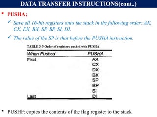
PUSHA ;
Save all 16-bit registers onto the stack in the following order: AX,
CX, DX, BX, SP, BP, SI, DI.
The value of the SP is that before the PUSHA instruction.
PUSHF; copies the contents of the flag register to the stack.
88.
DATA TRANSFER INSTRUCTIONS(cont..)
POPDESTINATION:
The POP instruction is used to perform the reverse of a PUSH.
Copies a word from the stack location pointed to by the stack pointer
to a destination specified in the Instruction.
The stack pointer is used to read 2 bytes of data and copy them into
the location specified in the operand field.
The destination can be :
A general-purpose register,
A segment register except CS and IP
A memory location.
The data in the stack is not changed.
89.
DATA TRANSFER INSTRUCTIONS(cont..)
After the word is copied to the specified destination, the stack pointer
is automatically incremented by 2 to point to the next word on the
stack.
No flags are affected by the POP instruction.
EXAMPLES:
POP DX ; Copy a word from top of stack to DX
; Increment SP by 2
POP DS ; Copy a word from top of stack to DS
; Increment SP by 2
NOTE: POP CS Is illegal.
90.
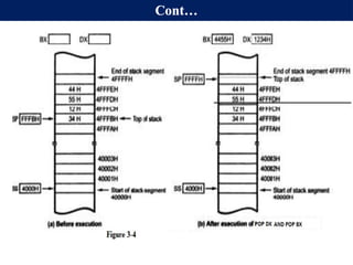
DATA TRANSFER INSTRUCTIONS(cont..)
EXAMPLES: Assume the contents of the stack segment register and
the stack pointer are 4000H and FFFBH, respectively. What is the
result of POP DX followed by POP BX? USE FIGURE 3.4 NEXT
PAGE.
SOLUTION:
The contents of location 4FFFBH (34H) are copied into the lower
byte of DX, and the contents of location 4FFFCH (12H) are copied
into the upper half of DX.
Similarly, the contents of location 4FFFDH (55H) are copied into
the lower byte of BX, and the contents of location 4FFFEH (44H)
are copied into the upper half of BX.
The stack pointer is then incremented a second time and points to
4FFFFH.
Fig. 3-4 shows a snap shot of memory contents in the stack area.
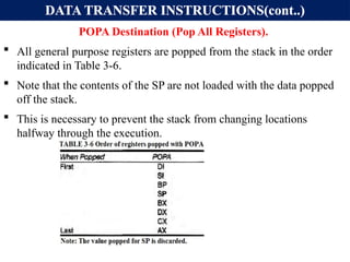
DATA TRANSFER INSTRUCTIONS(cont..)
POPADestination (Pop All Registers).
All general purpose registers are popped from the stack in the order
indicated in Table 3-6.
Note that the contents of the SP are not loaded with the data popped
off the stack.
This is necessary to prevent the stack from changing locations
halfway through the execution.
93.
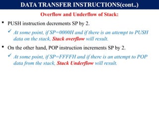
DATA TRANSFER INSTRUCTIONS(cont..)
Overflowand Underflow of Stack:
PUSH instruction decrements SP by 2.
At some point, if SP=0000H and if there is an attempt to PUSH
data on the stack, Stack overflow will result.
On the other hand, POP instruction increments SP by 2.
At some point, if SP=FFFFH and if there is an attempt to POP
data from the stack, Stack Underflow will result.
94.
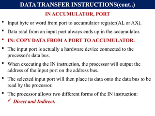
DATA TRANSFER INSTRUCTIONS(cont..)
INACCUMULATOR, PORT
Input byte or word from port to accumulator register(AL or AX).
Data read from an input port always ends up in the accumulator.
IN: COPY DATA FROM A PORT TO ACCUMULATOR.
The input port is actually a hardware device connected to the
processor's data bus.
When executing the IN instruction, the processor will output the
address of the input port on the address bus.
The selected input port will then place its data onto the data bus to be
read by the processor.
The processor allows two different forms of the IN instruction:
Direct and Indirect.
95.
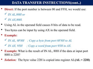
DATA TRANSFER INSTRUCTIONS(cont..)
Direct: If the port number is between 00 and FFH, we would use:
IN AL,80H or
IN AX,80H.
Using AL in the operand field causes 8 bits of data to be read.
Two bytes can be input by using AX in the operand field.
Example:
IN AL, 0F8H ; Copy a byte from port 0F8H to AL
IN AX, 95H ; Copy a word from port 95H to AX.
Example: What is the result of IN AL, 80H if the data at input port
80H is 22H?
Solution: The byte value 22H is copied into register AL(AL = 22H)
96.
DATA TRANSFER INSTRUCTIONS(cont..)
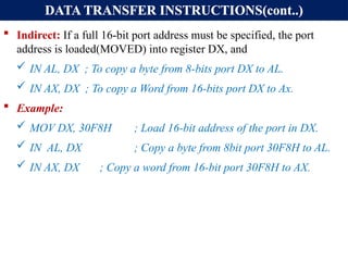
Indirect: If a full 16-bit port address must be specified, the port
address is loaded(MOVED) into register DX, and
IN AL, DX ; To copy a byte from 8-bits port DX to AL.
IN AX, DX ; To copy a Word from 16-bits port DX to Ax.
Example:
MOV DX, 30F8H ; Load 16-bit address of the port in DX.
IN AL, DX ; Copy a byte from 8bit port 30F8H to AL.
IN AX, DX ; Copy a word from 16-bit port 30F8H to AX.
97.
DATA TRANSFER INSTRUCTIONS(cont..)
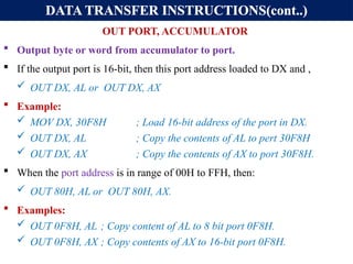
OUTPORT, ACCUMULATOR
Output byte or word from accumulator to port.
If the output port is 16-bit, then this port address loaded to DX and ,
OUT DX, AL or OUT DX, AX
Example:
MOV DX, 30F8H ; Load 16-bit address of the port in DX.
OUT DX, AL ; Copy the contents of AL to pert 30F8H
OUT DX, AX ; Copy the contents of AX to port 30F8H.
When the port address is in range of 00H to FFH, then:
OUT 80H, AL or OUT 80H, AX.
Examples:
OUT 0F8H, AL ; Copy content of AL to 8 bit port 0F8H.
OUT 0F8H, AX ; Copy contents of AX to 16-bit port 0F8H.
98.
DATA TRANSFER INSTRUCTIONS(cont..)
Example: What happens during execution of OUT DX, AL if AL
contains 7CH and DX contains 3000H?
Solution:
The port address stored in register DX is output on the address bus,
along with the 7C from AL on the data bus.
The output port circuitry must recognize address 3000H and store
the data.
99.
DATA TRANSFER INSTRUCTIONS(cont..)
LEADESTINATION, SOURCE (Load effective address):
This instruction is used to load the offset of the source memory
operand into one of the processor's registers.
The memory operand may be specified by any number of addressing
modes. The destination may not be a segment register.
Determines the offset of the variable or memory location named as
the source and loads this address in the specified 16-bit register.
Flags are not affected by LEA instruction.
Example:
LEA CX, TOTAL ; Load CX with offset of TOTAL in DS.
LEA AX, [BX] [DI] ; Load AX with EA = BX + DI
LEA DX, 10 [SI] ; LOAD DX with EA = SI + 10
100.
DATA TRANSFER INSTRUCTIONS(cont..)
Example: What is the difference between:
MOV AX, [40H] and LEA AX, [40H]?
Solution:
In MOV AX, [40H] ; Places 2 bytes of data from locations 40H
; and 41H into register AX.
In LEA AX, [40H] ; Places 40H into register AX.
Example: What does LEA AX, [SI] do?
Solution: The value of SI at execution time is loaded into AX.
Example:
MOV BX, 35H
MOV DI, 12H
LEA SI, [BX+DI] ; SI = 35H + 12H = 47H
101.
DATA TRANSFER INSTRUCTIONS(cont..)
XCHGDESTINATION, SOURCE (Exchange data):
Used to swap the contents of two 8-, or 16-bit operands.
One operand must be a processor register (excluding the segment
registers).
The other operand may be a register or a memory location.
If a memory location is used as an operand it is assumed to be within
a data segment.
Example: Registers AL and BL contain 30H and 40H, respectively.
What is the result of XCHG AL, BL?
Solution: After execution,
AL = BL = 40H and
BL =AL = 30H.

![8086 ADDRESSING MODES (CONT..)
C) DIRECT ADDRESSING MODE:
MOV REG, [constant] or MOV [constant], REG
Here constant is not operand but it is an offset or EA in memory of operand.
In the direct addressing mode the data is in some memory location(s) and the
address of the data in memory comes immediately after the instruction.
This address is the offset address and one can calculate the physical address
by shifting left the DS register and adding it to the offset as follows:
Example:
MOV DL, [2400H] ; move contents of DS: 2400H into DL
EXERCISE 3-1: Find the physical address of the memory location and its
contents after the execution of the following,
MOV AL, 99H
MOV [3518H], AL ;Assuming that DS = 1512H.](https://image.slidesharecdn.com/chapter3-250228061409-185792e0/85/Microprocessor-Chapter3-hawassa-Univetsi-6-320.jpg)
![Cont…
Direct addressing mode:
address of the data in memory comes immediately after the
instruction operand is a constant
The address is the offset address. The offset address is put in a
rectangular bracket
Ex: MOV DL,[2400] ; move contents of DS:2400H into DL
Physical address of DS:3518 => 15120+3518=18638H
The memory location 18638H will contain the value 99H](https://image.slidesharecdn.com/chapter3-250228061409-185792e0/85/Microprocessor-Chapter3-hawassa-Univetsi-7-320.jpg)
![8086 ADDRESSING MODES (CONT..)
D) REGISTER INDIRECT ADDRESSING MODE:
MOV REG1, [REG2] or MOV [REG2], REG1;
Here the address of the memory location where the operand resides is held
by a register, REG2.
REG1 can be any general purpose register and REG2 can be either of SI, DI,
or BX and they must be combined with DS in order to generate the 20-bit
physical address.
Example:
MOV AL, [BX] ; move contents of DS:BX into AL
MOV CL, [SI] ; move contents of DS:SI into CL
MOV [DI], AH ; move contents of AH into DS:DI
MOV DX, [BX] ; move contents of DS:BX into DL and
; contents of DS:BX+1 into DH](https://image.slidesharecdn.com/chapter3-250228061409-185792e0/85/Microprocessor-Chapter3-hawassa-Univetsi-8-320.jpg)
![8086 ADDRESSING MODES (CONT..)
Exercise:
Assume that DS = 1120H, SI = 2498H, and AX = 17FEH.
Show the contents of memory locations and its contents after the
execution of MOV [SI], AX.
Solution:
The contents of AX are moved into memory locations with logical address
DS: SI and DS: SI + 1;
Therefore, the physical address starts at:
PA = DS (shifted left) + SI = 13698H.
According to the little endian convention,
low address 13698H contains FEH, the low byte, and
high address 13699H will contain 17H, the high byte.](https://image.slidesharecdn.com/chapter3-250228061409-185792e0/85/Microprocessor-Chapter3-hawassa-Univetsi-9-320.jpg)
![8086 ADDRESSING MODES (CONT..)
E) BASED RELATIVE ADDRESSING MODE:
MOV REG1, [REG2] + CONST or
MOV [REG2] + CONST, REG1;
CONST is an 8-bit displacement value.
REG1 can be any general purpose register and REG2 can only be either of
BP or BX
In the based relative addressing mode, base registers BX and BP, as well as a
displacement value, are used to calculate what is called the effective address.
The default segments used for the calculation of the physical address (PA)
are DS for BX and SS for BP.
PA = DS*10H + BX + const ; EA = BX + const
PA = SS*10H + BP + const ; EA = BP + const](https://image.slidesharecdn.com/chapter3-250228061409-185792e0/85/Microprocessor-Chapter3-hawassa-Univetsi-10-320.jpg)
![8086 ADDRESSING MODES (CONT..)
EXAMPLES: Determine PA and EA
MOV CX, [BX]+10 ; move DS:BX + 10 and DS:BX+10+1 into CX.
PA = DS*10H + BX + 10, EA = BX + 10
MOV AL, [BP] + 5 ;
PA = SS*10H + BP + 5
EA = BP + 5
Alternative codings for MOV reg1, [reg2] + constant is
MOV reg1, [reg2 + constant] or
MOV reg1, const[reg2]
For instance, MOV CX, [BX]+10 is same as
MOV CX, [BX+10] or
MOV CX, 10[BX]](https://image.slidesharecdn.com/chapter3-250228061409-185792e0/85/Microprocessor-Chapter3-hawassa-Univetsi-11-320.jpg)
![8086 ADDRESSING MODES (CONT..)
F) INDEXED RELATIVE ADDRESSING MODE:
MOV REG1, [REG2] + CONST OR
MOV [REG2] + CONST, REG1;
The indexed relative addressing mode works the same as the based relative
addressing mode, except that registers DI and SI hold the offset address.
Constant is an 8-bit displacement value.
REG1 can be any general purpose register and REG2 can only be either of
DI or SI
PA = DS*10H + DI + const ; EA=DI + const or
PA = DS*10H + SI + const ; EA= SI + const
Examples:
MOV DX, [SI]+5 ; PA = DS (shifted left) + SI + 5
MOV CL, [DI]+20 ; PA = DS (shifted left) + DI + 20](https://image.slidesharecdn.com/chapter3-250228061409-185792e0/85/Microprocessor-Chapter3-hawassa-Univetsi-12-320.jpg)
![8086 ADDRESSING MODES (CONT..)
EXERCISE 3-3:
Assume that DS = 4500, SS = 2000, BX = 2100, SI = 1486, DI = 8500, BP =
7814, and AX = 2512. Show the exact physical memory location where AX is
stored in each of the following. All values are in hex.
a) MOV [BX]+20, AX
b) MOV [SI]+10, AX
c) MOV [DI]+4, AX
d) MOV [BP]+12, AX
Solution: In each case PA = segment register (shifted left) + offset register +
displacement.
a. DS:BX+20 ;location 47120 = (12) and 47121 =(25)
b. DS:SI+10 ;location 46496 = (12) and 46497 = (25)
c. DS:DI+4 ;location 4D504 = (12) and 4D505 = (25)
d. SS:BP+12 ;location 27826 = (12) and 27827 = (25)](https://image.slidesharecdn.com/chapter3-250228061409-185792e0/85/Microprocessor-Chapter3-hawassa-Univetsi-13-320.jpg)
![8086 ADDRESSING MODES (CONT..)
G) BASED INDEXED ADDRESSING MODE:
MOV REG1, [REG2][REG3] + CONST OR
MOV [REG2][REG3] + CONST, REG1;
In this mode, one base register and one index register are used.
REG1 can be any general purpose register and REG2 can only be either of DI or SI
and reg3 can only be either of BX or BP.
PA= DS*10H+BX+DI + const; EA=DI+BX+ const or PA=SS*10H+BP+SI+const
and EA= SI + BP + const
EXAMPLES:
MOV CL, [BX][DI]+8 ;PA = DS (shifted left) + BX + DI + 8
MOV CH, [BX][SI]+20 ;PA = DS (shifted left) + BX + SI + 20
MOV AH, [BP][SI]+29 ;PA = SS (shifted left) + BP + SI + 29
MOV AH, [BP][DI]+29 ;PA = SS (shifted left) + BP + DI + 29
Note that "MOV AX, [SI][DI]+displacement" is illegal.](https://image.slidesharecdn.com/chapter3-250228061409-185792e0/85/Microprocessor-Chapter3-hawassa-Univetsi-14-320.jpg)
![Comparison of addressing modes
Mode Algorithm Advantage Disadvantage
Register EA= R No memory
reference
Limited address
space
Immediate Operand =A No memory
reference
Limited operand
magnitude
Direct EA=A simple Limited address
space
Register Indirect EA=[R] Large address
space
Extra memory
reference
Displacement EA= A+[R] flexibility complexity](https://image.slidesharecdn.com/chapter3-250228061409-185792e0/85/Microprocessor-Chapter3-hawassa-Univetsi-19-320.jpg)
![Hu, Institute Of Technology Department Of Electrical And Computer Engineering 20
Quiz-1
1. Show how the flag register is
affected by:
Mov BX, AAA9H
Add BX, 5557H
2. Assume that SS=4567H, DS =
1120H, ES=4567H, SI = 2498H, and
AX = 17FEH. Show the contents of
memory locations and its contents
after the execution of MOV [SI], AX.](https://image.slidesharecdn.com/chapter3-250228061409-185792e0/85/Microprocessor-Chapter3-hawassa-Univetsi-20-320.jpg)
![INTRODUCTION TO ASSEMBLY LANGUAGE PROGRAMMING
An Assembly language program is :
A series of statements, or lines which is, either Assembly language
instructions, or Pseudo-instruction called Directives.
Directives (pseudo-instructions):
Give directions to the assembler about how it should translate the
Assembly language instructions into machine code.
Assembly language instructions consist of four fields:
[label:] mnemonic [operands] [;comment]
Brackets indicate that the field is optional, do not type in the brackets.
The comment field begins with a ";" and may be at the end of a line. The
assembler ignores comments.
Comments are optional, but highly recommended to make it easier to
read and understand the program.](https://image.slidesharecdn.com/chapter3-250228061409-185792e0/85/Microprocessor-Chapter3-hawassa-Univetsi-22-320.jpg)
![FULL SEGMENT DEFINITION
SEGMENT DEFINITION:
The SEGMENT and ENDS directives indicate the beginning &
ending of a segment, in this format:
The label, or name, must follow naming conventions and be
unique.
The [options] field gives important information to the assembler
for organizing the segment, but is not required.
The ENDS label must be the same label as in the SEGMENT
directive.
In full segment definition, the ".MODEL" directive is not used.](https://image.slidesharecdn.com/chapter3-250228061409-185792e0/85/Microprocessor-Chapter3-hawassa-Univetsi-60-320.jpg)
![FULL SEGMENT DEFINITION
In "MOV AL, [BX] " the BX register is the offset of the data
segment.
On transfer of control from OS to the program, of the three segment
registers, only CS and SS have the proper values.
The DS value (and ES) must be initialized by the program](https://image.slidesharecdn.com/chapter3-250228061409-185792e0/85/Microprocessor-Chapter3-hawassa-Univetsi-66-320.jpg)
![DATA TRANSFER INSTRUCTIONS:
Some times, For example, in MOV [SI], 0 the processor does not
know if the operand should be coded as a byte value, or as word
value.
For cases like this, we use BYTE PTR and WORD PTR directives
to indicate the size of data.
If you wish to MOV a byte value into memory, use:
MOV BYTE PTR [SI], 0
MOV WORD PTR [SI], 0
The byte ptr, and word ptr assembler directives stand for "byte
pointer," and "word pointer."](https://image.slidesharecdn.com/chapter3-250228061409-185792e0/85/Microprocessor-Chapter3-hawassa-Univetsi-75-320.jpg)
![DATA TRANSFER INSTRUCTIONS(cont..)
LEA DESTINATION, SOURCE (Load effective address):
This instruction is used to load the offset of the source memory
operand into one of the processor's registers.
The memory operand may be specified by any number of addressing
modes. The destination may not be a segment register.
Determines the offset of the variable or memory location named as
the source and loads this address in the specified 16-bit register.
Flags are not affected by LEA instruction.
Example:
LEA CX, TOTAL ; Load CX with offset of TOTAL in DS.
LEA AX, [BX] [DI] ; Load AX with EA = BX + DI
LEA DX, 10 [SI] ; LOAD DX with EA = SI + 10](https://image.slidesharecdn.com/chapter3-250228061409-185792e0/85/Microprocessor-Chapter3-hawassa-Univetsi-99-320.jpg)
![DATA TRANSFER INSTRUCTIONS(cont..)
Example: What is the difference between:
MOV AX, [40H] and LEA AX, [40H]?
Solution:
In MOV AX, [40H] ; Places 2 bytes of data from locations 40H
; and 41H into register AX.
In LEA AX, [40H] ; Places 40H into register AX.
Example: What does LEA AX, [SI] do?
Solution: The value of SI at execution time is loaded into AX.
Example:
MOV BX, 35H
MOV DI, 12H
LEA SI, [BX+DI] ; SI = 35H + 12H = 47H](https://image.slidesharecdn.com/chapter3-250228061409-185792e0/85/Microprocessor-Chapter3-hawassa-Univetsi-100-320.jpg)