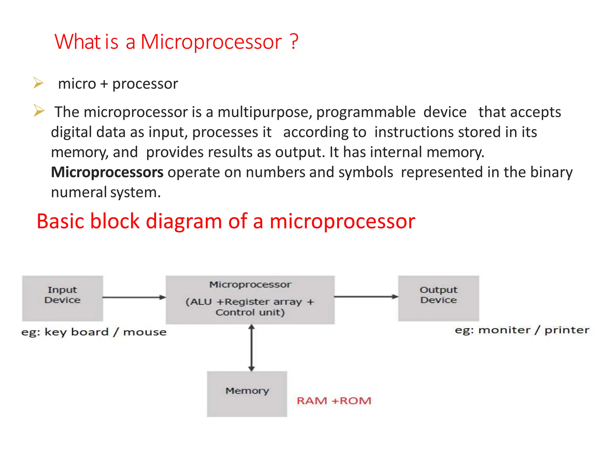
The document provides information about microprocessors and the Intel 8086 microprocessor. It discusses what a microprocessor is and the basic block diagram of a microprocessor. It then describes some key features of the Intel 8086 including that it is a 16-bit microprocessor with a 20-bit address bus and 14 general purpose registers. The document details the internal architecture of the 8086 including the execution unit, flag register, and bus interface unit. It also explains the various addressing modes and instruction set of the 8086 microprocessor.

![Memory Address (Offset) Is Directly Specified In
The Instruction .
MOV AX, [5000h]
Here, data besides in a memory location in the data
segment.
Physical Address Of Memory Location Is Calculated Using
DS And Offset Value 5000H.
DIRECT ADDRESSING MODE](https://image.slidesharecdn.com/8086microprocessor-240114060334-4a23eb62/75/8086-microprocessor-pptx-JNTUH-ece-3rd-year-36-2048.jpg)
![REGISTER INDIRECT ADDRESSING MODE
•The Offset Address Of Data Is In Either BX Or SI Or DI
Registers. The Default Segment Is Either DS Or ES.
• Example: MOV AX, [BX]
• Here, Data Is Present In A Memory Location In DS Whose
Offset Address Is In BX.
•The Effective Address Of The Data Is Given As 10H*DS+ [BX].](https://image.slidesharecdn.com/8086microprocessor-240114060334-4a23eb62/75/8086-microprocessor-pptx-JNTUH-ece-3rd-year-38-2048.jpg)
![INDEXED ADDRESSING MODE
Eg: MOV AX, [SI].
Here, data is available at an offset address stored in SI in DS.
REGISTER RELATIVE ADDRESSING MODE
Eg: MOV Ax, 50H [BX].
Here, physical address is given as10H*DS+50H+ [BX].](https://image.slidesharecdn.com/8086microprocessor-240114060334-4a23eb62/75/8086-microprocessor-pptx-JNTUH-ece-3rd-year-39-2048.jpg)
![BASED INDEXED ADDRESSING MODE
MOV AX, [BX] [SI].
Here, BX is the base register and SI is the index register.
The physical address is computed as is the index register.
The physical address is computed as 10H*DS+[BX]+[SI].](https://image.slidesharecdn.com/8086microprocessor-240114060334-4a23eb62/75/8086-microprocessor-pptx-JNTUH-ece-3rd-year-40-2048.jpg)
![eg: MOV AX, 50H[BX][SI]
Here, 50H is an immediate displacement, BX is a base
register and SI is Here, 50H is an immediate
displacement, BX is a base register and SI is an index
register.
The physical address of data is computed as
10H*DS+[BX] + [SI] + 50H.
RELATIVE BASED INDEXED ADDRESSING MODE](https://image.slidesharecdn.com/8086microprocessor-240114060334-4a23eb62/75/8086-microprocessor-pptx-JNTUH-ece-3rd-year-41-2048.jpg)
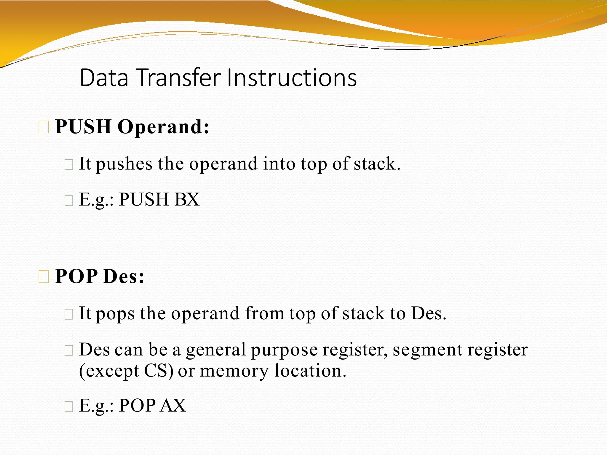
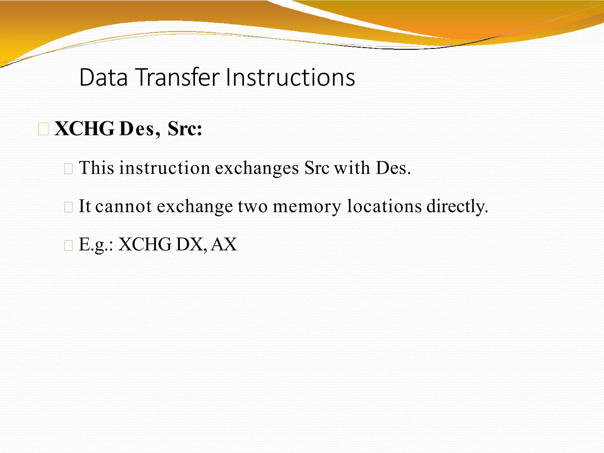
![Data Transfer Instructions
MOV Des, Src:
Src operand can be register, memory location or immediate
operand.
Des can be register or memory operand.
Both Src and Des cannot be memory location at the same
time.
E.g.:
MOV CX, 037AH
MOV AL, BL
MOV BX, [0301 H]](https://image.slidesharecdn.com/8086microprocessor-240114060334-4a23eb62/75/8086-microprocessor-pptx-JNTUH-ece-3rd-year-44-2048.jpg)
![Data Transfer Instructions
LEA Register, Src:
It loads a 16-bit register with the offset
address of the data specified by the Src.
E.g.: LEABX, [DI]
This instruction loads the contents of DI
(offset) into the BXregister.](https://image.slidesharecdn.com/8086microprocessor-240114060334-4a23eb62/75/8086-microprocessor-pptx-JNTUH-ece-3rd-year-48-2048.jpg)
![Data Transfer Instructions
LDS Des, Src:
It loads 32-bit pointer from memory source to
destination register andDS.
The offset is placed in the destination register and the
segment is placed inDS.
To use this instruction the word at the lower memory
address must contain the offset and the word at the
higher address must contain the segment.
E.g.: LDS BX, [0301 H]](https://image.slidesharecdn.com/8086microprocessor-240114060334-4a23eb62/75/8086-microprocessor-pptx-JNTUH-ece-3rd-year-49-2048.jpg)
![Data Transfer Instructions
LESDes, Src:
It loads 32-bit pointer from memory source to
destination register andES.
The offset is placed in the destination register and the
segment is placed inES.
This instruction is very similar to LDS except that it
initializes ES instead of DS.
E.g.: LES BX, [0301 H]](https://image.slidesharecdn.com/8086microprocessor-240114060334-4a23eb62/75/8086-microprocessor-pptx-JNTUH-ece-3rd-year-50-2048.jpg)
![Arithmetic Instructions
ADD Des, Src:
It adds a byte to byte or a word to word.
It effects AF, CF, OF, PF, SF, ZF flags.
E.g.:
ADD AL, 74H
ADD DX,AX
ADD AX, [BX]](https://image.slidesharecdn.com/8086microprocessor-240114060334-4a23eb62/75/8086-microprocessor-pptx-JNTUH-ece-3rd-year-52-2048.jpg)
![Arithmetic Instructions
ADC Des, Src:
It adds the two operands with CF.
It effects AF, CF, OF, PF, SF, ZF flags.
E.g.:
ADC AL, 74H
ADC DX,AX
ADC AX, [BX]](https://image.slidesharecdn.com/8086microprocessor-240114060334-4a23eb62/75/8086-microprocessor-pptx-JNTUH-ece-3rd-year-53-2048.jpg)
![Arithmetic Instructions
SUB Des, Src:
It subtracts a byte from byte or a word from word.
It effects AF, CF, OF, PF, SF, ZF flags.
For subtraction, CF acts as borrow flag.
E.g.:
SUBAL, 74H
SUB DX, AX
SUBAX, [BX]](https://image.slidesharecdn.com/8086microprocessor-240114060334-4a23eb62/75/8086-microprocessor-pptx-JNTUH-ece-3rd-year-54-2048.jpg)
![Arithmetic Instructions
SBB Des, Src:
It subtracts the two operands and also the
borrow from the result.
It effects AF, CF, OF, PF, SF, ZF flags.
E.g.:
SBBAL, 74H
SBBDX,AX
SBBAX, [BX]](https://image.slidesharecdn.com/8086microprocessor-240114060334-4a23eb62/75/8086-microprocessor-pptx-JNTUH-ece-3rd-year-55-2048.jpg)