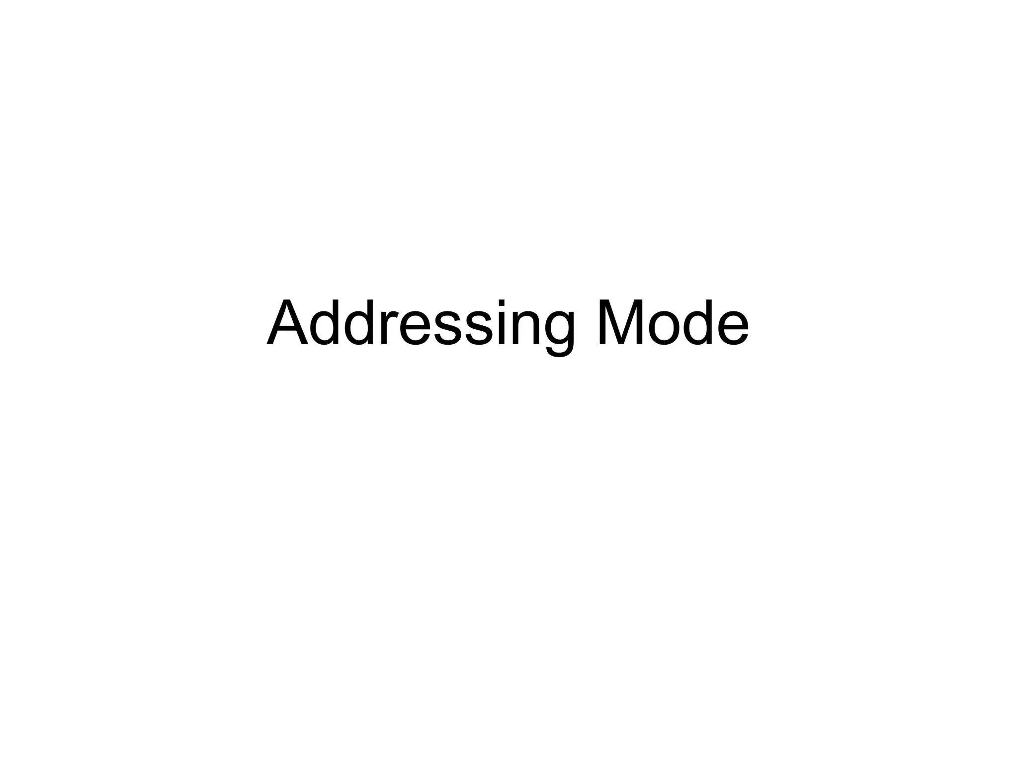
8086 Microprocessor Register
8086Registers Category
Category Bit Register Name
General Purpose Register 16 AX,BX,CX,DX
General Purpose Register 8 AH,AL,BH,BL,CH,CL,DH,DL
Pointer Register 16 SP (Stack Pointer)
BP (Base Pointer)
Index Register 16 SI (Source Index)
DI (Destination Index)
Segment Register 16 CS (Code Segment)
DS (Data Segment)
SS (Stack Segment)
ES (Extra Segment)
Instruction Pointer Register 16 IP (Instruction Pointer)
Status Register (Flag) 16 DR (Flag Register)
3.
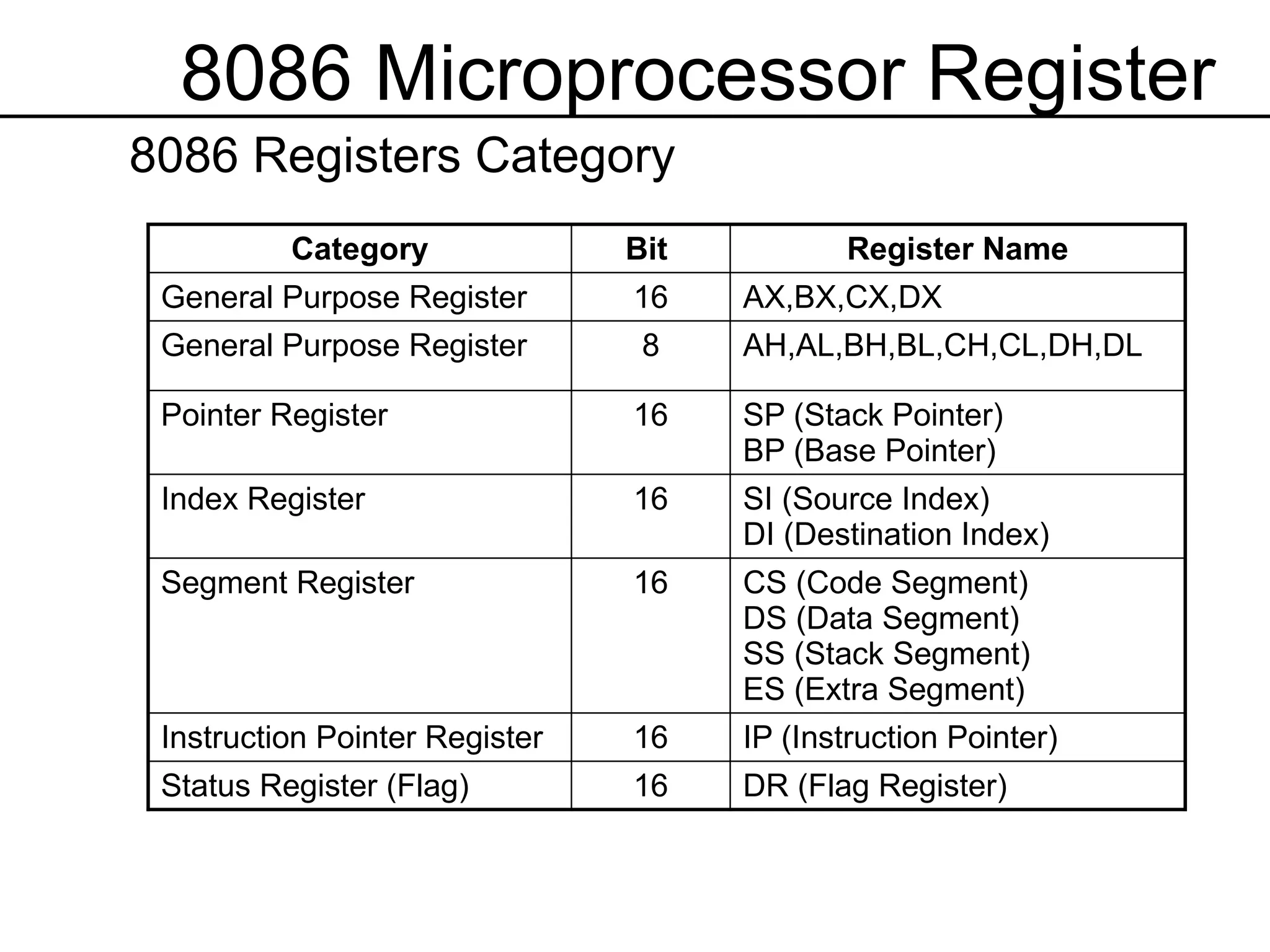
General Purpose Registers
•This register is used for general data manipulation
• Even CPU able to operate on the data stored in memory,
the same data can be process much faster if it is in
register
• The function for 16-bit 8086 microprocessor register is as
follows
Register Function
AX Accumulator Register
For arithmetic, logic and data transfer operation
BX Base Register
Also as address register
CX Count Register
Used for loop counter, shift and rotate bits
DX Data Register
Used in division and multiplication also I/O operation
4.
Segment Register
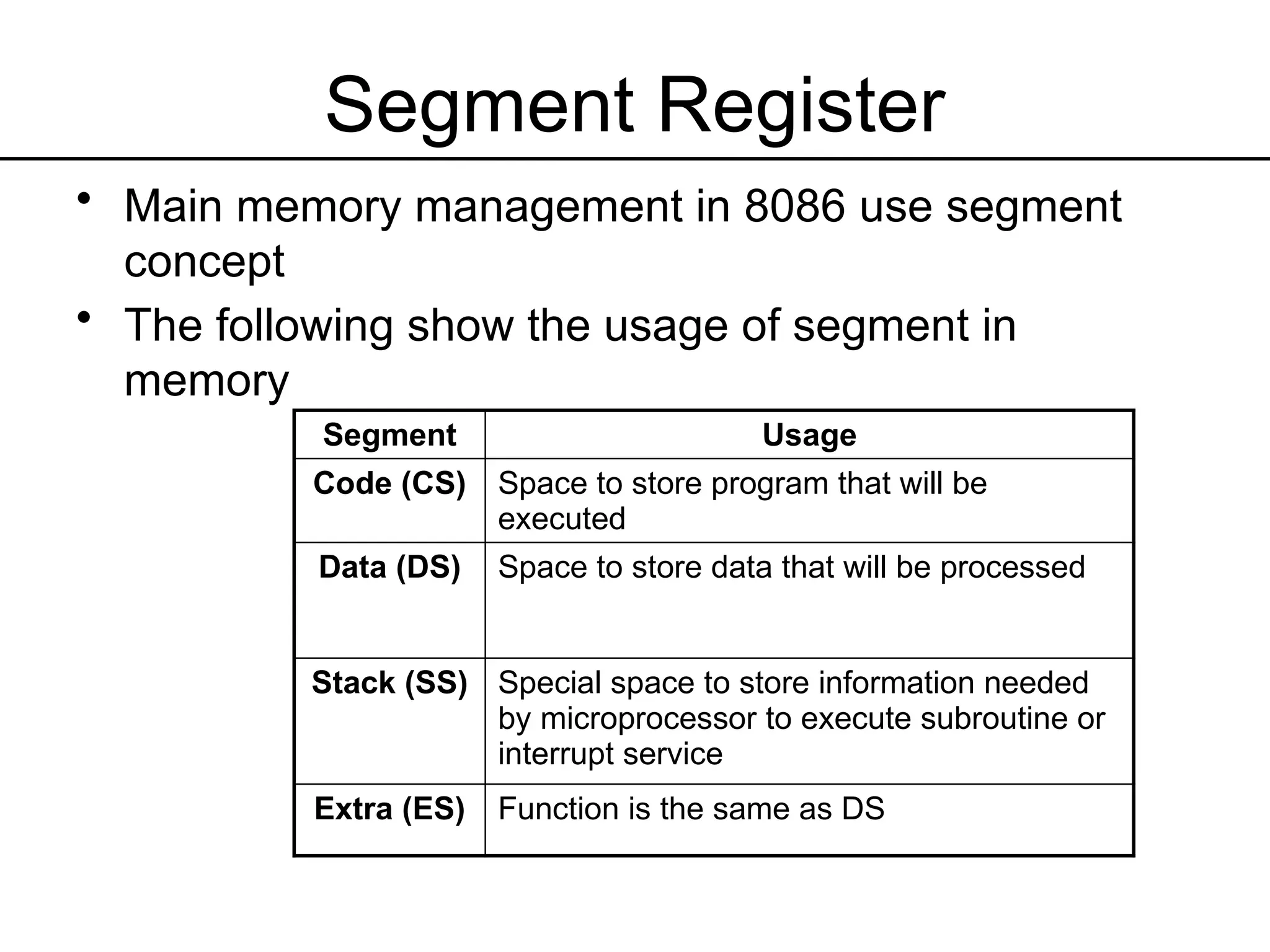
• Mainmemory management in 8086 use segment
concept
• The following show the usage of segment in
memory
Segment Usage
Code (CS) Space to store program that will be
executed
Data (DS) Space to store data that will be processed
Stack (SS) Special space to store information needed
by microprocessor to execute subroutine or
interrupt service
Extra (ES) Function is the same as DS
5.
Instruction Pointer Register(IP)
• Register which stores instruction address
to be executed
• Each time instruction is fetch from memory
to be executed in processor, IP content will
be added so that it always show to the
next instruction
• If branch instruction, the IP content will be
loaded with new value which is the branch
address
6.
Index Register andPointer
• This registers is used for storing relative shifting
value for memory address location
• There are 2 pointer register:
– Stack Pointer (SP) – point to the top stack
– Base Pointer (BP) – used for fetch data in data
segment
• There are 2 index register:
– Source Index (SI) – contains offset address for source
operand in data segment
– Destination Index (DI) - contains offset value for
destination operand in DS
7.
Flag/Status Register
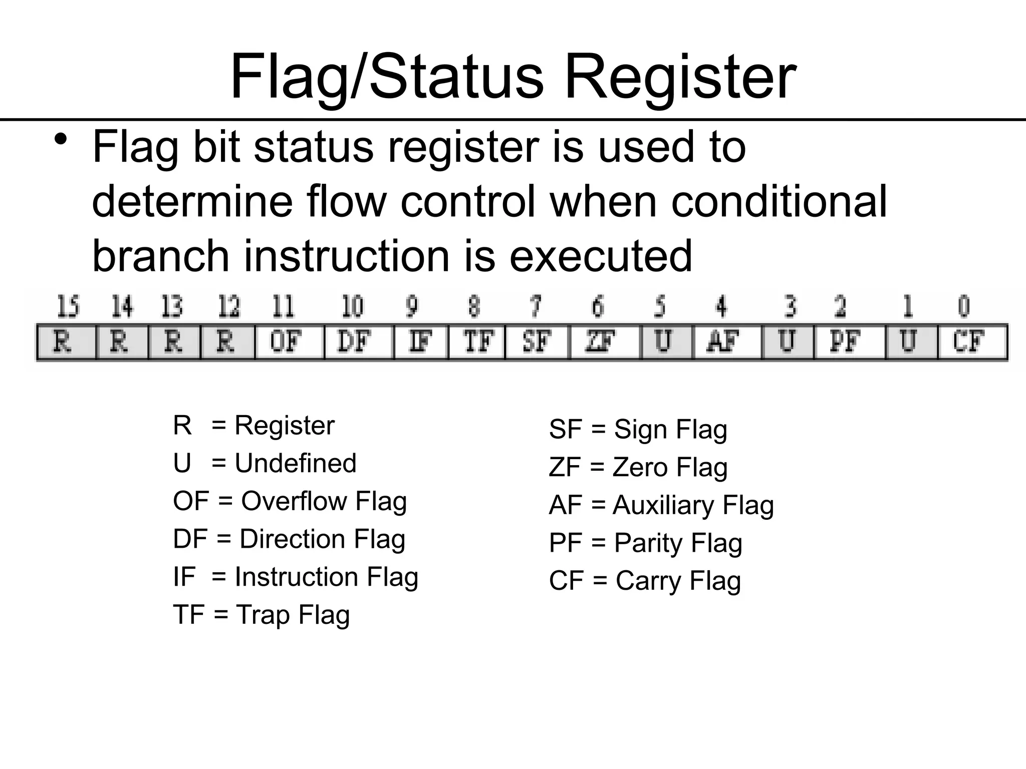
• Flagbit status register is used to
determine flow control when conditional
branch instruction is executed
R = Register
U = Undefined
OF = Overflow Flag
DF = Direction Flag
IF = Instruction Flag
TF = Trap Flag
SF = Sign Flag
ZF = Zero Flag
AF = Auxiliary Flag
PF = Parity Flag
CF = Carry Flag
8.
Addressing Mode
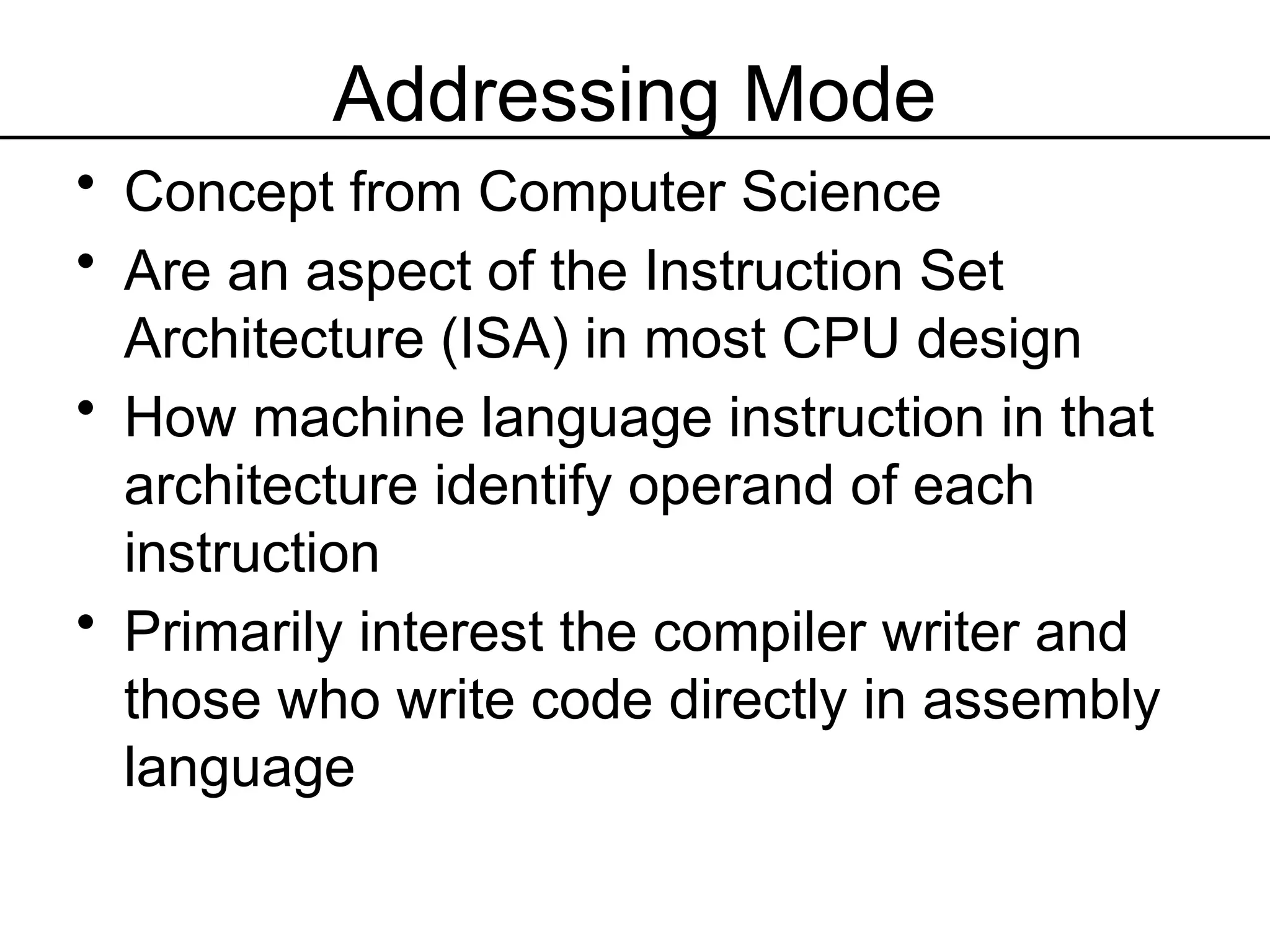
• Conceptfrom Computer Science
• Are an aspect of the Instruction Set
Architecture (ISA) in most CPU design
• How machine language instruction in that
architecture identify operand of each
instruction
• Primarily interest the compiler writer and
those who write code directly in assembly
language
9.
Addressing Mode
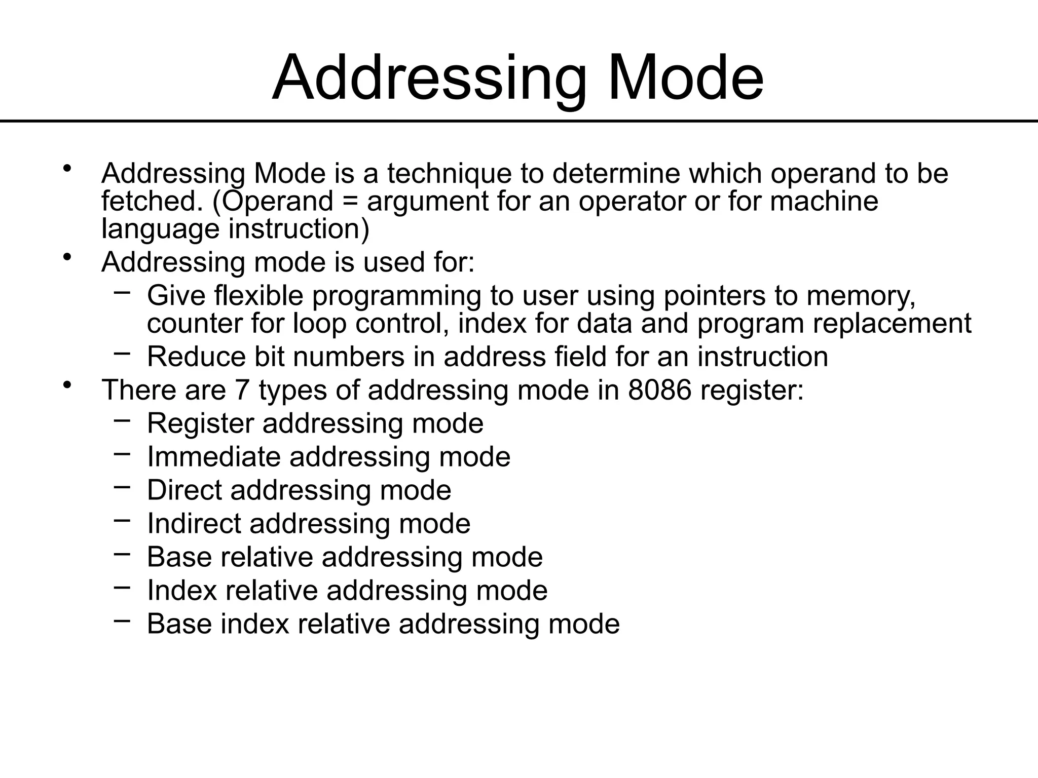
• AddressingMode is a technique to determine which operand to be
fetched. (Operand = argument for an operator or for machine
language instruction)
• Addressing mode is used for:
– Give flexible programming to user using pointers to memory,
counter for loop control, index for data and program replacement
– Reduce bit numbers in address field for an instruction
• There are 7 types of addressing mode in 8086 register:
– Register addressing mode
– Immediate addressing mode
– Direct addressing mode
– Indirect addressing mode
– Base relative addressing mode
– Index relative addressing mode
– Base index relative addressing mode
10.
Addressing Mode
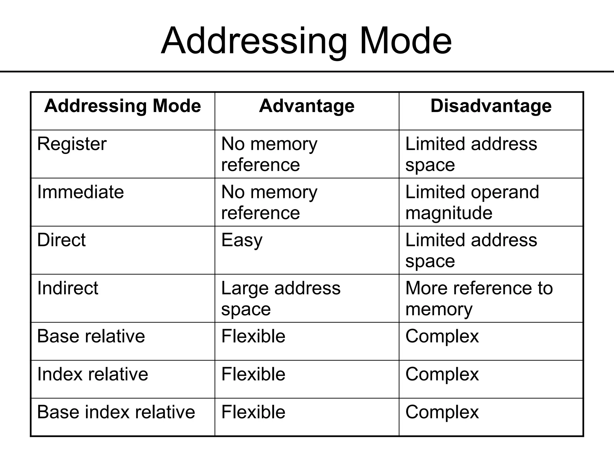
Addressing ModeAdvantage Disadvantage
Register No memory
reference
Limited address
space
Immediate No memory
reference
Limited operand
magnitude
Direct Easy Limited address
space
Indirect Large address
space
More reference to
memory
Base relative Flexible Complex
Index relative Flexible Complex
Base index relative Flexible Complex
11.
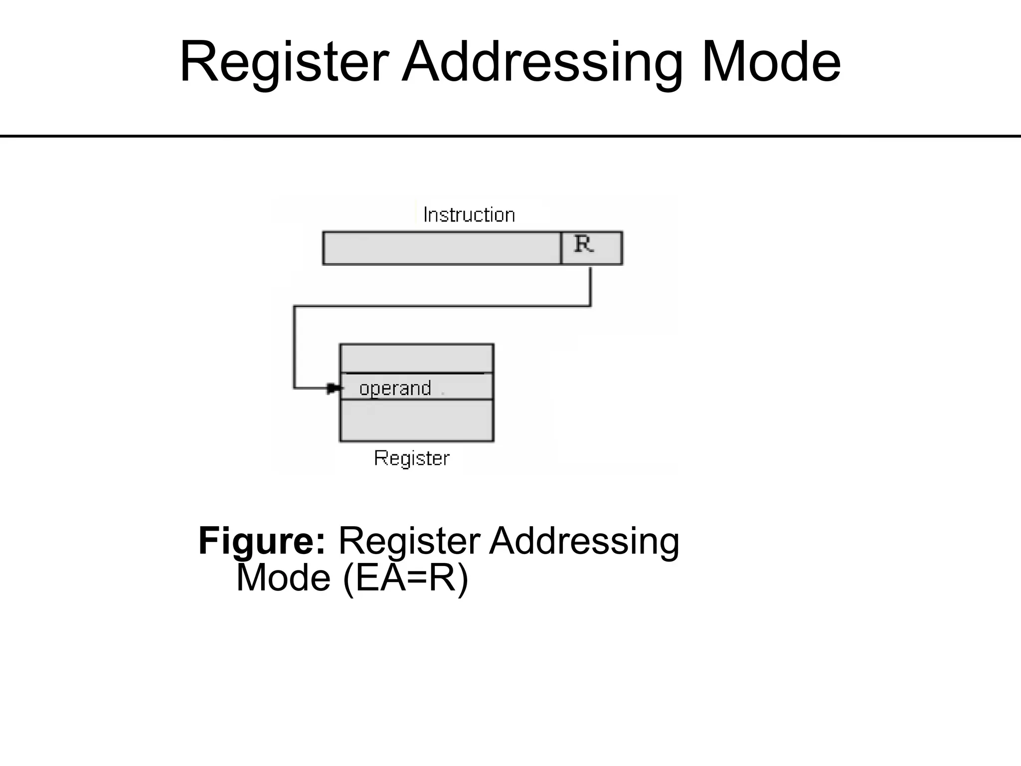
Register Addressing Mode
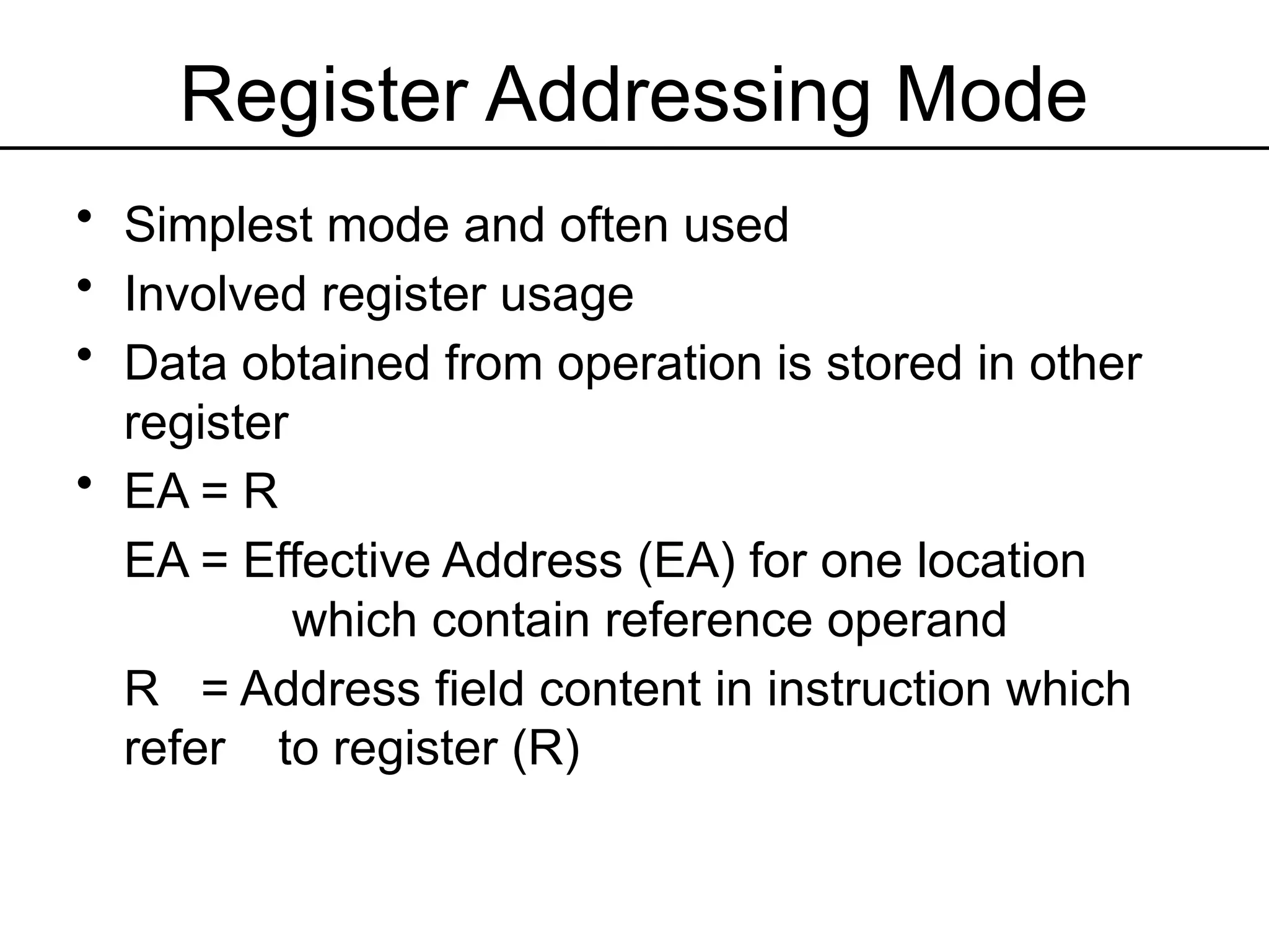
•Simplest mode and often used
• Involved register usage
• Data obtained from operation is stored in other
register
• EA = R
EA = Effective Address (EA) for one location
which contain reference operand
R = Address field content in instruction which
refer to register (R)
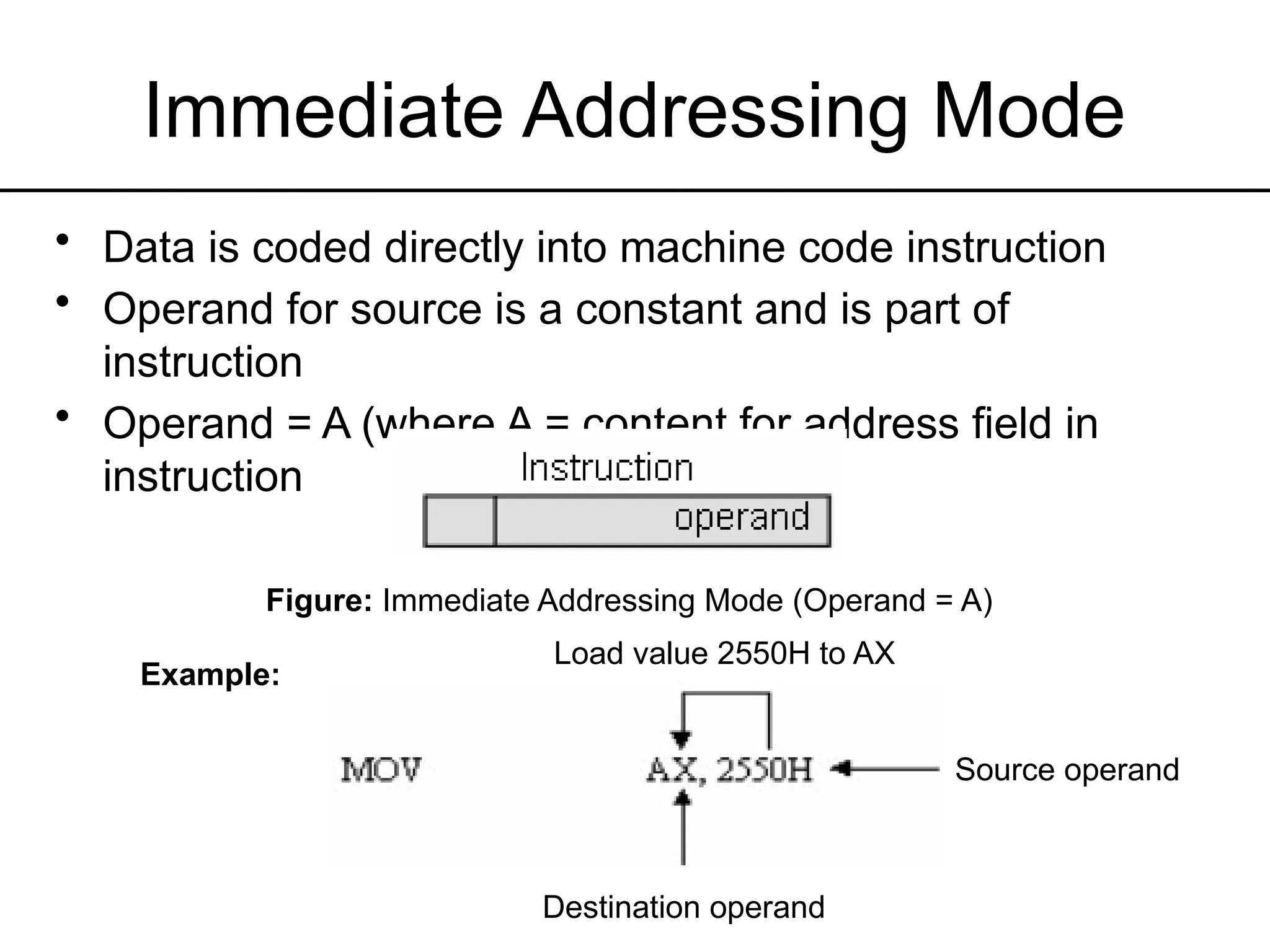
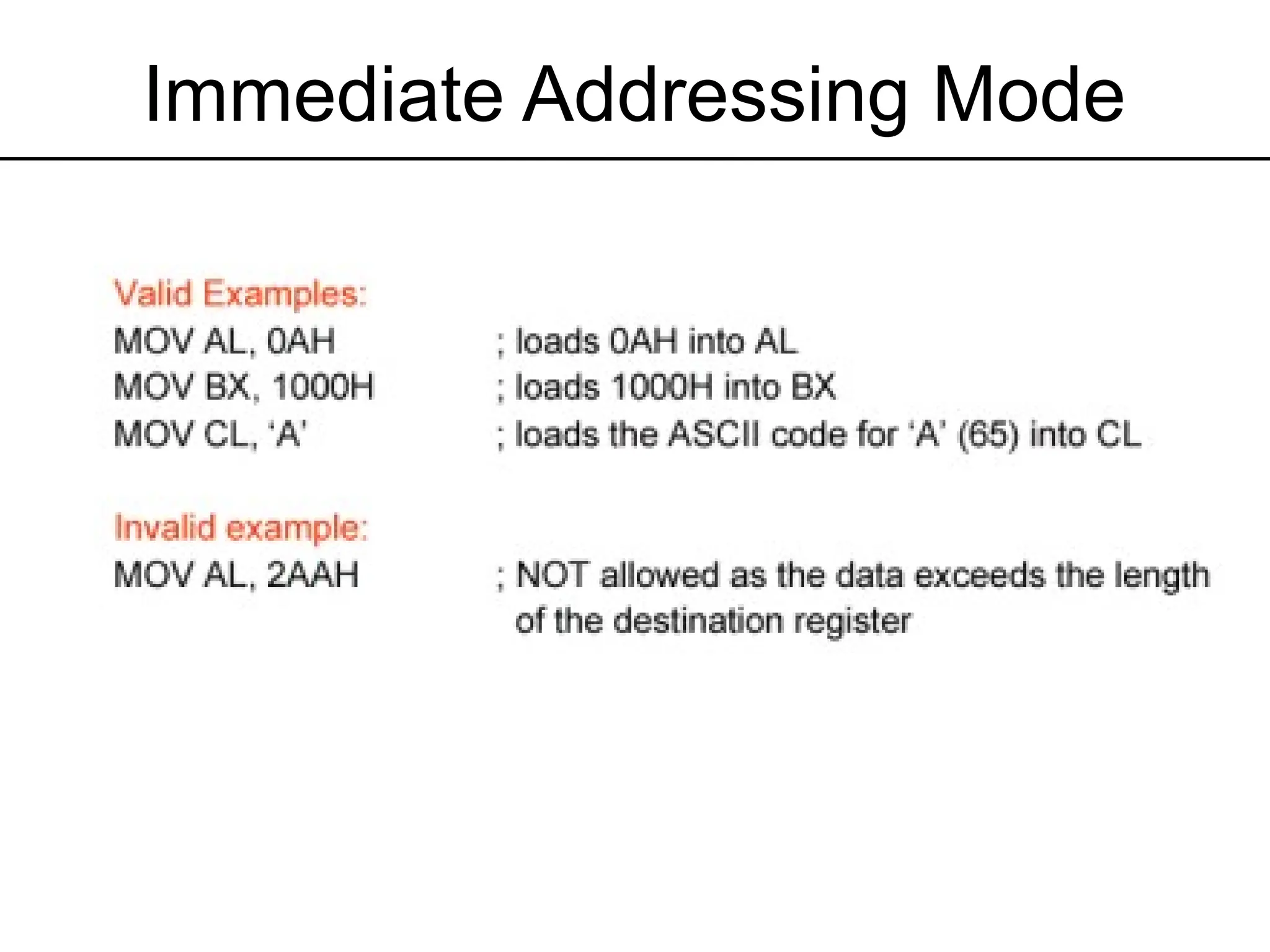
Immediate Addressing Mode
•Data is coded directly into machine code instruction
• Operand for source is a constant and is part of
instruction
• Operand = A (where A = content for address field in
instruction
Figure: Immediate Addressing Mode (Operand = A)
Example:
Load value 2550H to AX
Destination operand
Source operand
16.
Immediate Addressing Mode
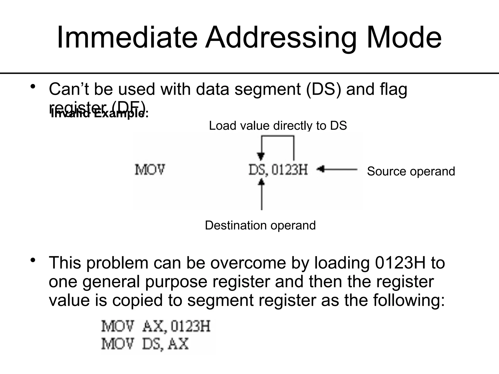
•Can’t be used with data segment (DS) and flag
register (DF)
• This problem can be overcome by loading 0123H to
one general purpose register and then the register
value is copied to segment register as the following:
Invalid Example:
Load value directly to DS
Destination operand
Source operand
Direct Addressing Mode
•Operand is stored in memory location, commonly data
segment (DS)
• Source operand is the address not immediate data (written in
[ ])
• This address is effective address which is the address of 16-
bit offset for operand storage location (from current DS value)
• Effective address need to be coupled with DS content to get
the true operand address (physical address)
EA = A
EA = Effective address for
location that contains
referred operand
A = Content for address field in
one instruction
19.
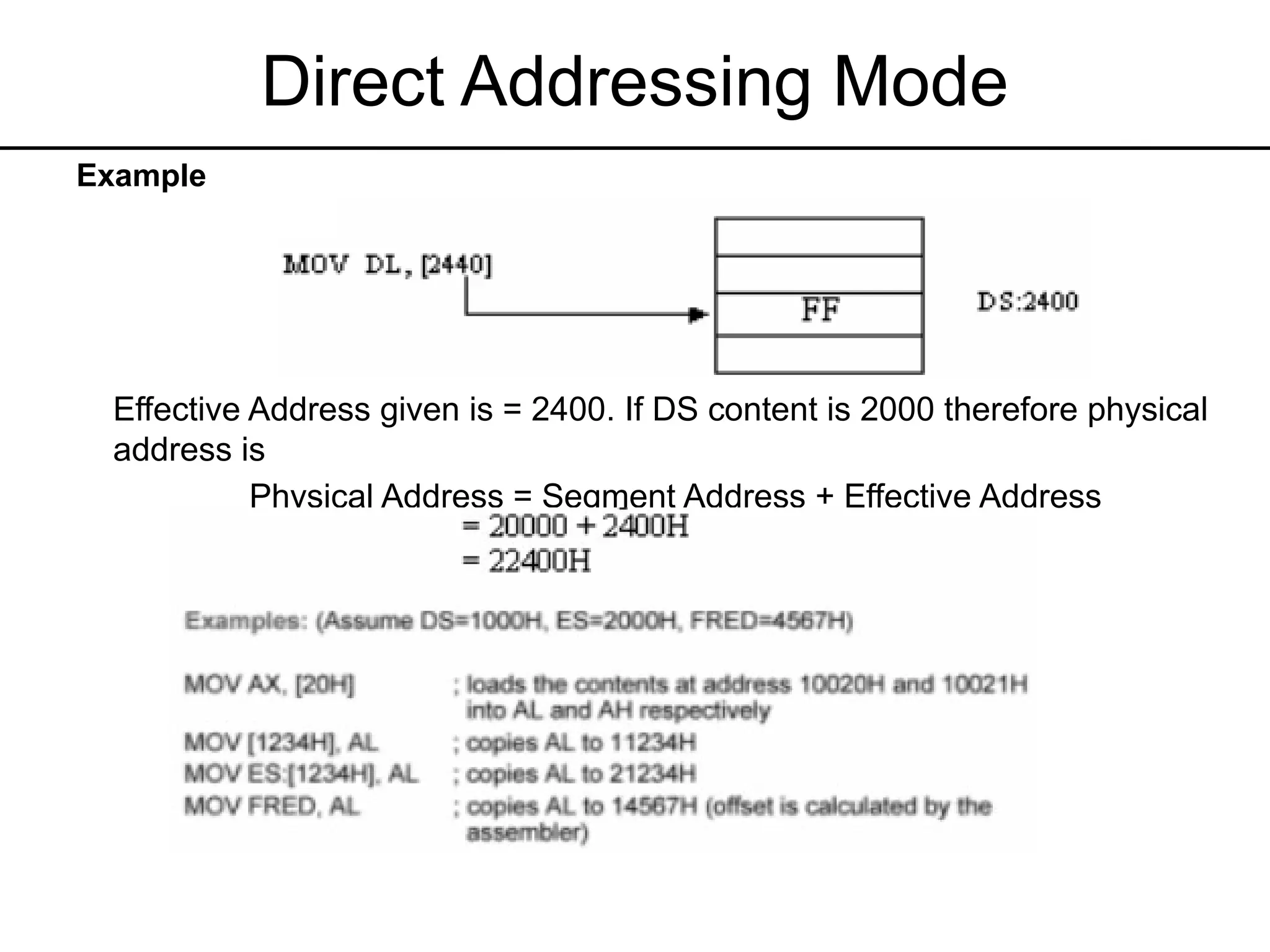
Direct Addressing Mode
Example
EffectiveAddress given is = 2400. If DS content is 2000 therefore physical
address is
Physical Address = Segment Address + Effective Address
20.
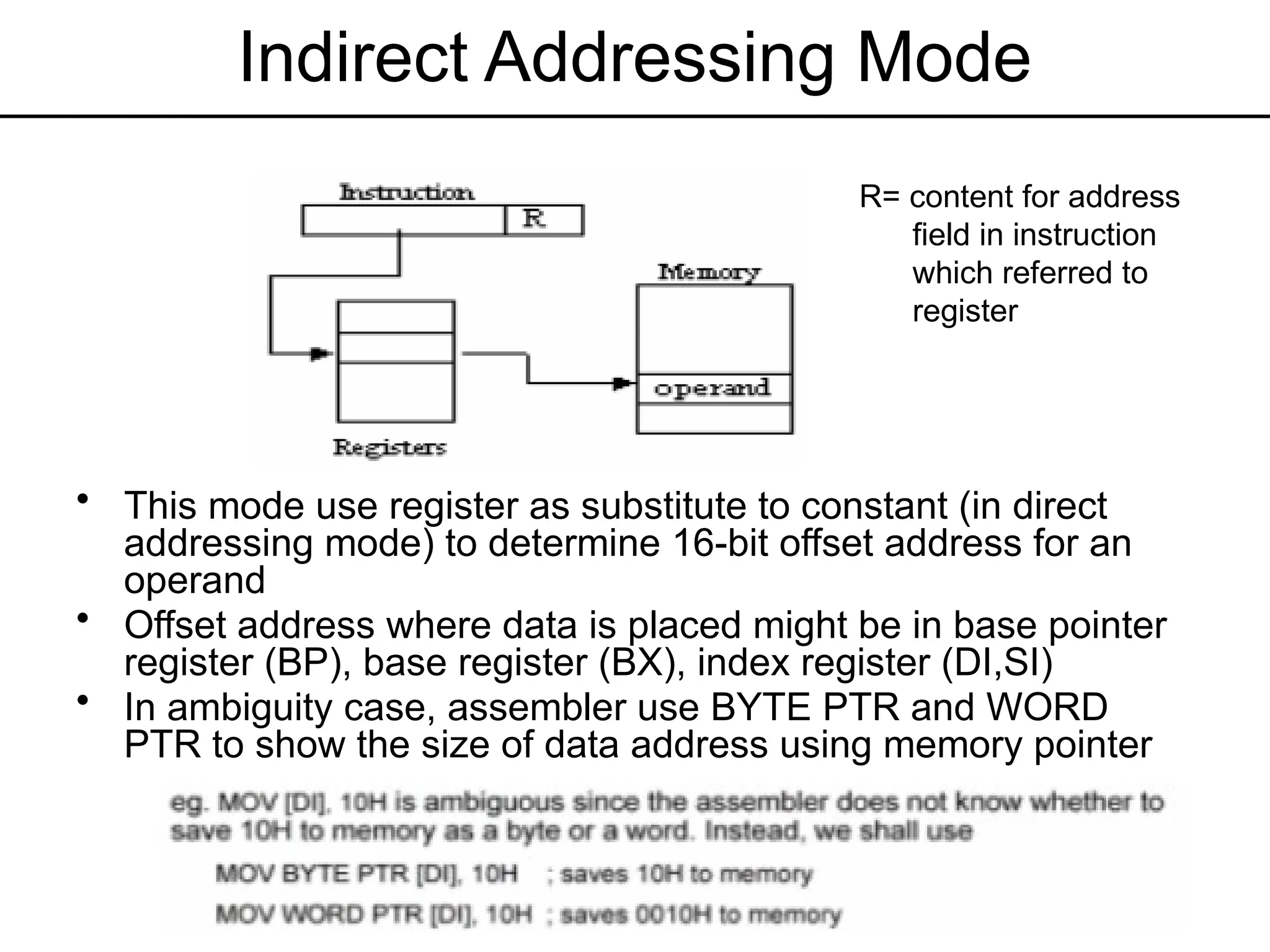
Indirect Addressing Mode
•This mode use register as substitute to constant (in direct
addressing mode) to determine 16-bit offset address for an
operand
• Offset address where data is placed might be in base pointer
register (BP), base register (BX), index register (DI,SI)
• In ambiguity case, assembler use BYTE PTR and WORD
PTR to show the size of data address using memory pointer
R= content for address
field in instruction
which referred to
register
21.
Indirect Addressing Mode
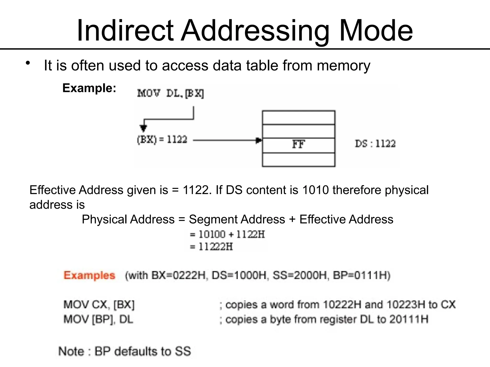
•It is often used to access data table from memory
Example:
Effective Address given is = 1122. If DS content is 1010 therefore physical
address is
Physical Address = Segment Address + Effective Address
22.
Base Relative AddressingMode
• Operand located in address obtained from addition of 8 or 16
bit displacement into one of BX or BP and the result is then
combined with segment data (DS/SS)
• This 8 or 16- bit displacement must be specified in operand
field and translated as signed two’s compliment
• For 8-bit, displacement must in the range of -128 to +127
• For 16-bit, displacement must in the range of -32768 to
+32767
• Effective Address = [Base register] + displacement
Physical Address = DS/SS = [Base register] + displacement
23.
Base Relative AddressingMode
Effective Address = Register [BX] + displacement
Example:
If DS content is 4000 therefore physical address is:
Physical Address = Segment Address + Effective Address
24.
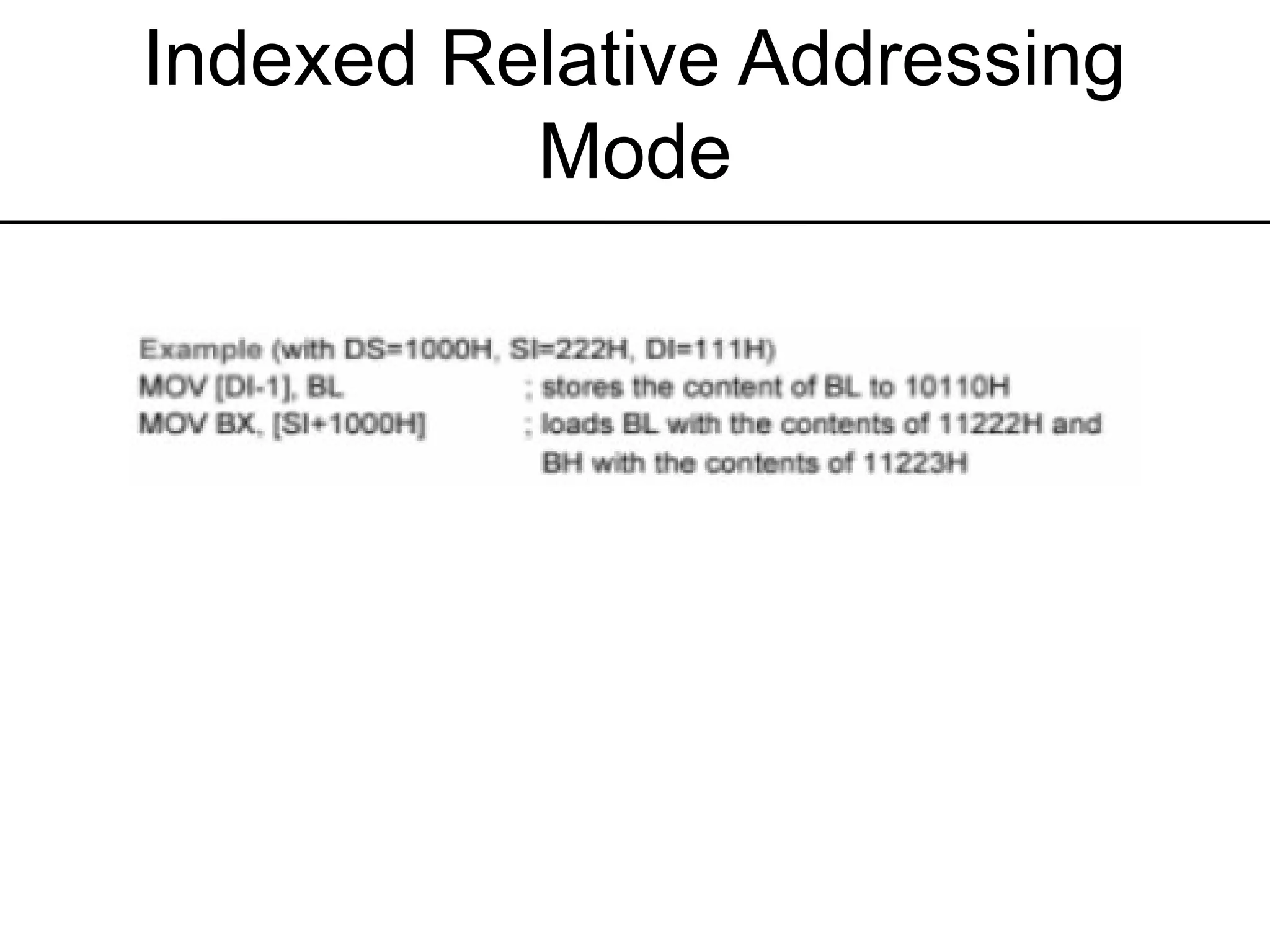
Indexed Relative AddressingMode
• The same as base addressing except that index register
(SI/DI) is used
• Operand is at given address by signed 8 or 16-bit
displacement addition to one of SI or DI and the result is then
added with segment register (DS=Default)
Example
MOV DX, ARRAY [SI]
Effective address = register [SI] + ARRAY
= 5000 + 1234H
= 6234H
If DS content is 2000, therefore the physical address is
Physical address = Segment address + Effective
address
= 20000H + 6234H
=26234H
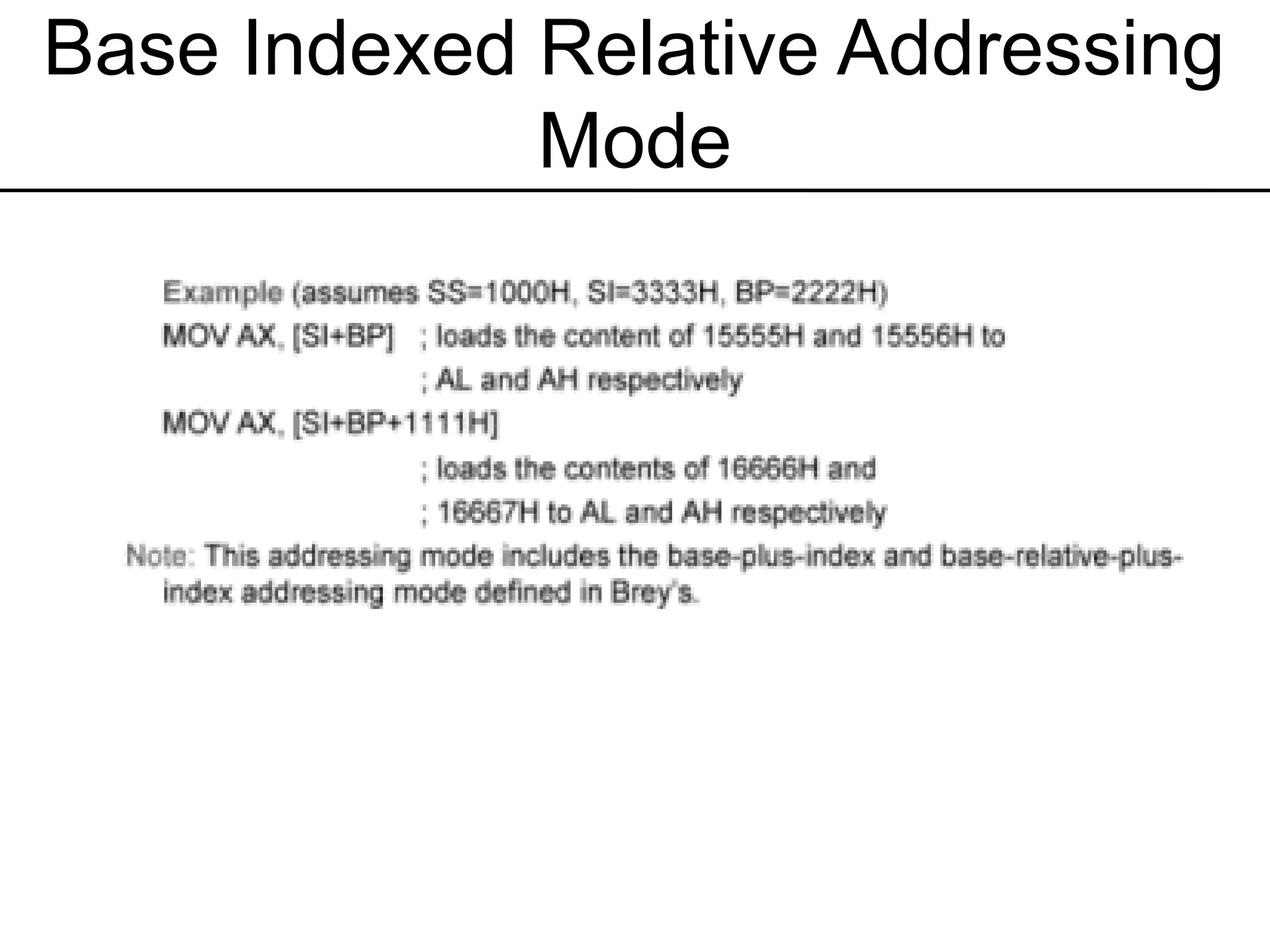
Base Indexed RelativeAddressing
Mode
• Combine base addressing mode and indexed addressing
mode
• Base register (BX?BP) is added to index register (DI/SI) as
positive integer (each register is in the range of 0 to 65535)
• As default, segment address is obtained from DS except for
BP register which is obtained form SS
• Effective Address = [base address] + [index register] +
displacement
Example
Let say BX = 1000X, SI = 2000H, BETA = 1234H, DS =1200H
Effective Address = register [BX] + register [SI] + ARRAY
Physical Address = Segment address + Effective address
MOV
REG, memory
memory, REG
REG,REG
memory,
immediate
REG,
immediate
SREG,
memory
memory,
SREG
REG, SREG
SREG, REG
Copy operand2 to operand1.
The MOV instruction cannot:
set the value of the CS and IP registers.
copy value of one segment register to another
segment register (should copy to general register
first).
copy immediate value to segment register (should
copy to general register first).
Algorithm:
operand1 = operand2
Example:
ORG 100h
MOV AX, 0B800h ; set AX = B800h (VGA memory).
MOV DS, AX ; copy value of AX to DS.
MOV CL, 'A' ; CL = 41h (ASCII code).
MOV CH, 01011111b ; CL = color attribute.
MOV BX, 15Eh ; BX = position on screen.
MOV [BX], CX ; w.[0B800h:015Eh] = CX.
RET ; returns to operating system.
C Z S O P A
unchanged
29.
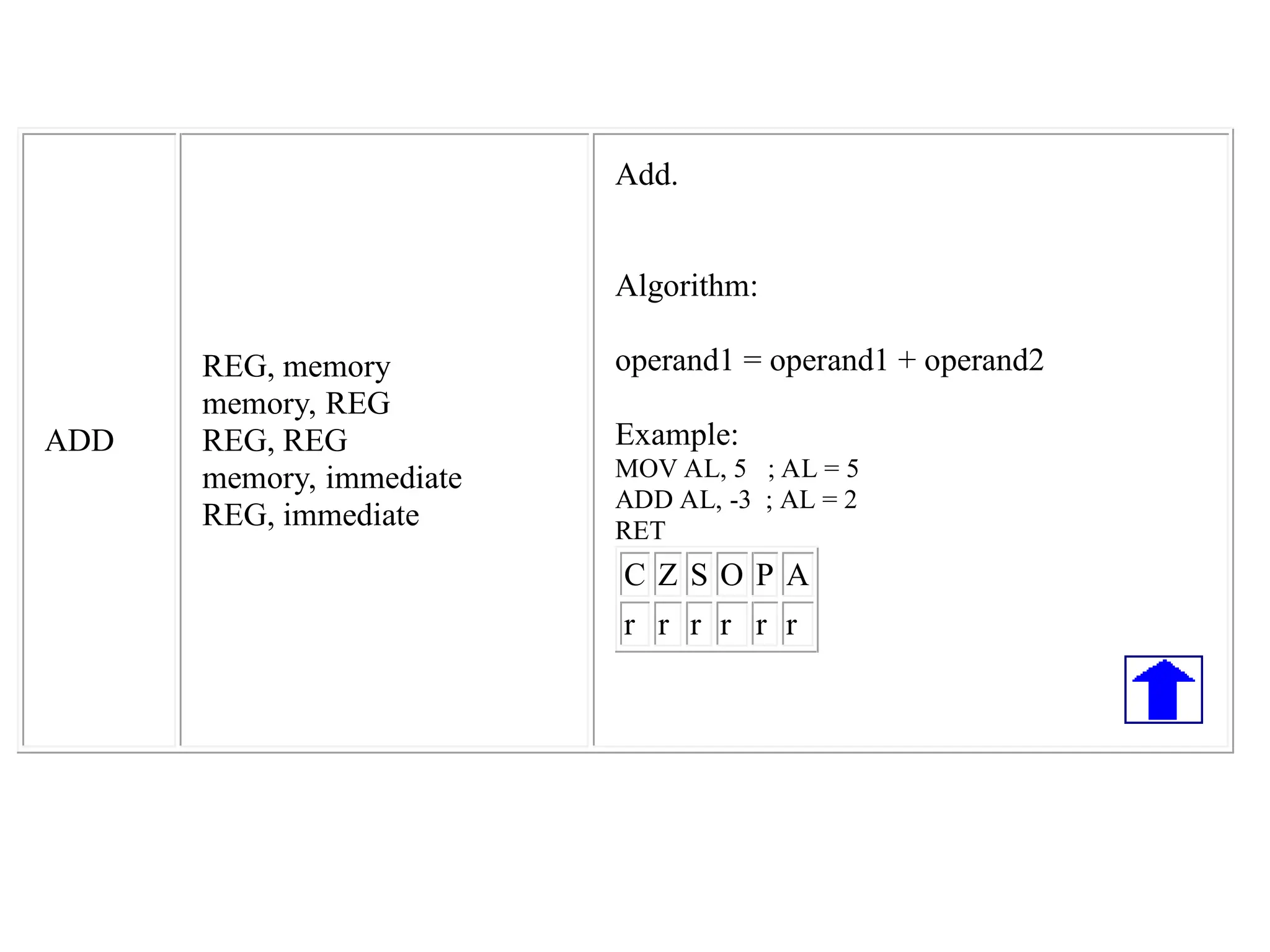
ADD
REG, memory
memory, REG
REG,REG
memory, immediate
REG, immediate
Add.
Algorithm:
operand1 = operand1 + operand2
Example:
MOV AL, 5 ; AL = 5
ADD AL, -3 ; AL = 2
RET
C Z S O P A
r r r r r r
30.
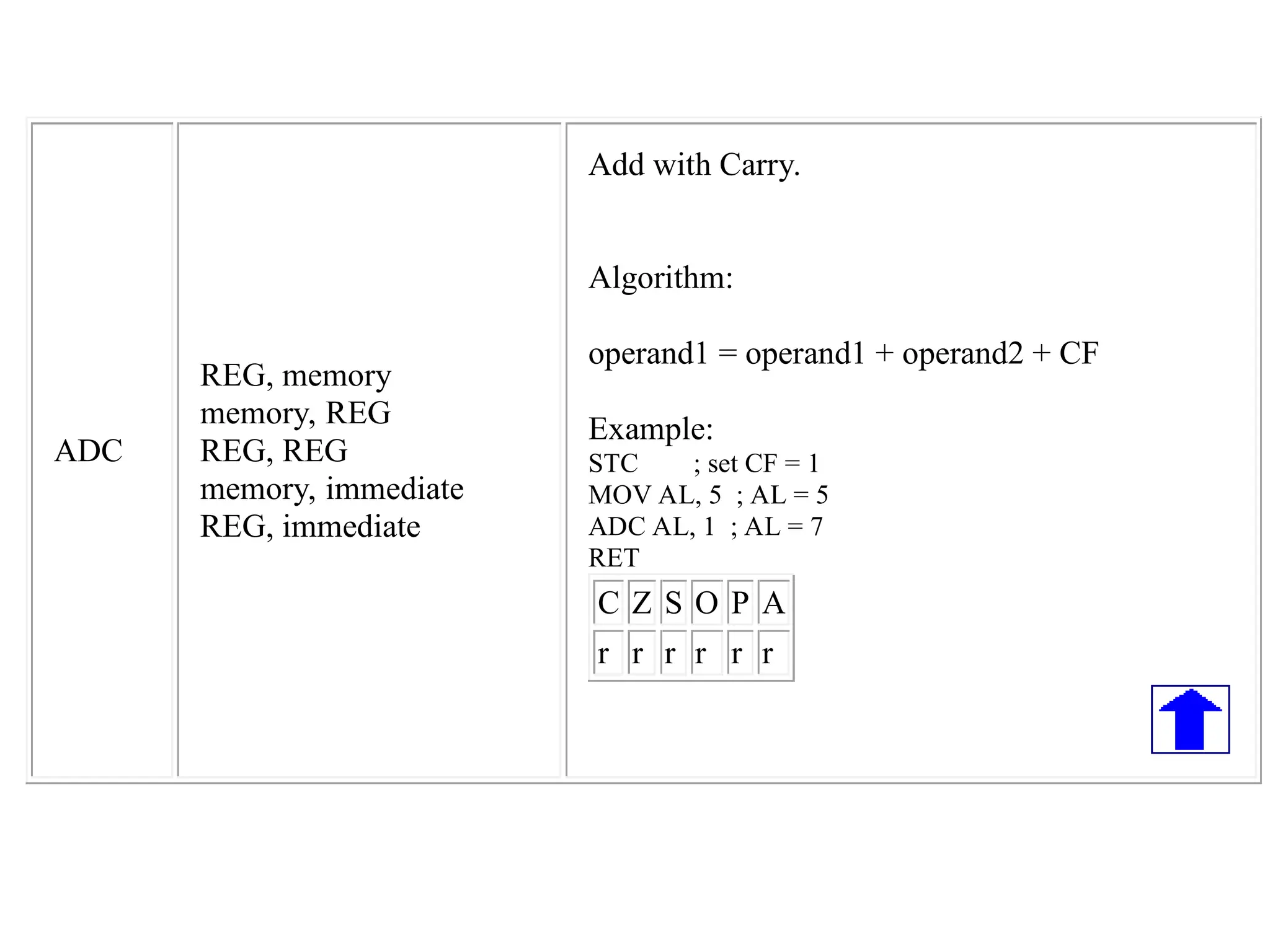
ADC
REG, memory
memory, REG
REG,REG
memory, immediate
REG, immediate
Add with Carry.
Algorithm:
operand1 = operand1 + operand2 + CF
Example:
STC ; set CF = 1
MOV AL, 5 ; AL = 5
ADC AL, 1 ; AL = 7
RET
C Z S O P A
r r r r r r
31.
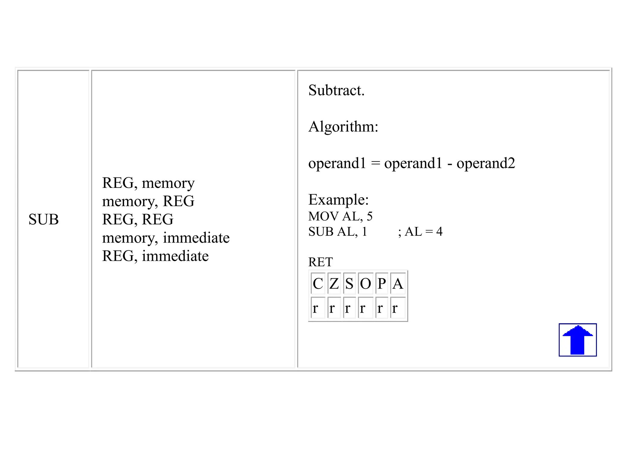
SUB
REG, memory
memory, REG
REG,REG
memory, immediate
REG, immediate
Subtract.
Algorithm:
operand1 = operand1 - operand2
Example:
MOV AL, 5
SUB AL, 1 ; AL = 4
RET
C Z S O P A
r r r r r r
32.
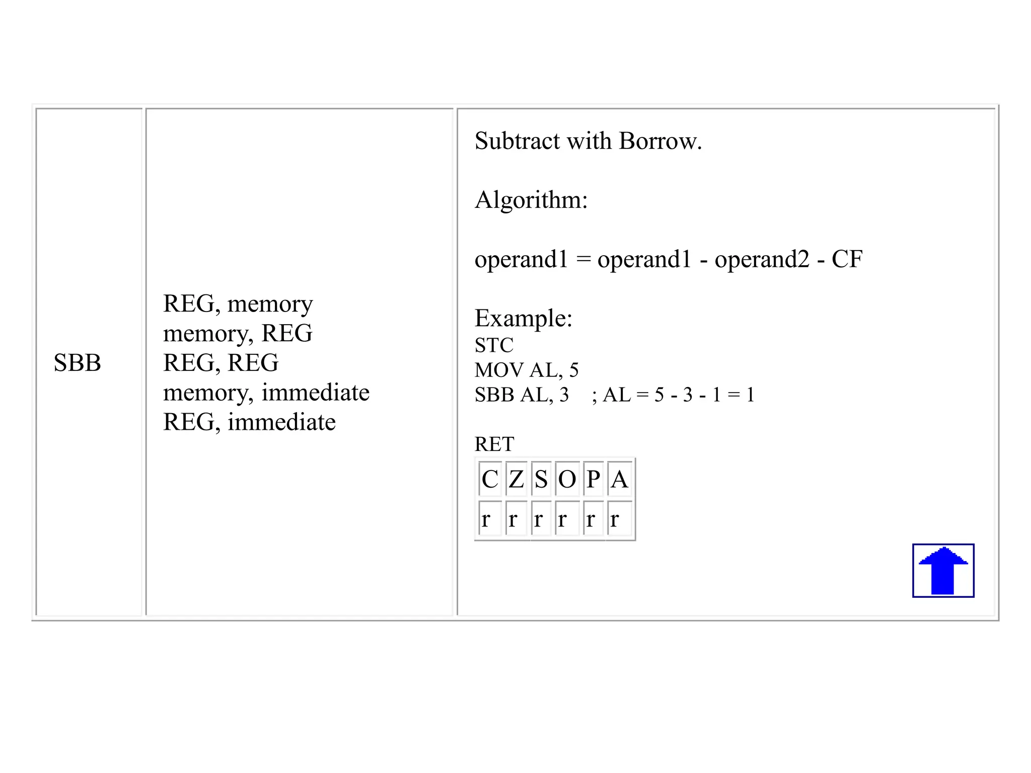
SBB
REG, memory
memory, REG
REG,REG
memory, immediate
REG, immediate
Subtract with Borrow.
Algorithm:
operand1 = operand1 - operand2 - CF
Example:
STC
MOV AL, 5
SBB AL, 3 ; AL = 5 - 3 - 1 = 1
RET
C Z S O P A
r r r r r r
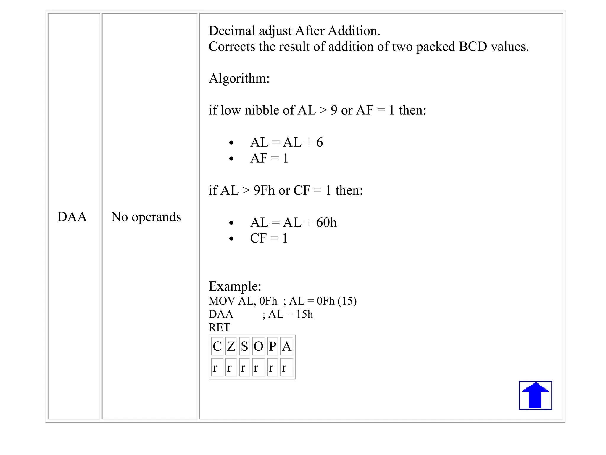
DAA No operands
Decimaladjust After Addition.
Corrects the result of addition of two packed BCD values.
Algorithm:
if low nibble of AL > 9 or AF = 1 then:
AL = AL + 6
AF = 1
if AL > 9Fh or CF = 1 then:
AL = AL + 60h
CF = 1
Example:
MOV AL, 0Fh ; AL = 0Fh (15)
DAA ; AL = 15h
RET
C Z S O P A
r r r r r r
36.
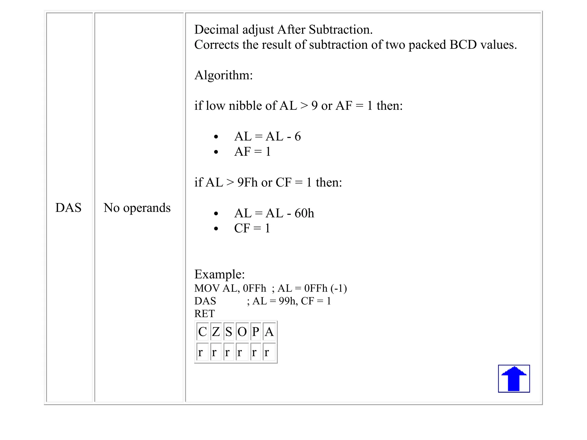
DAS No operands
Decimaladjust After Subtraction.
Corrects the result of subtraction of two packed BCD values.
Algorithm:
if low nibble of AL > 9 or AF = 1 then:
AL = AL - 6
AF = 1
if AL > 9Fh or CF = 1 then:
AL = AL - 60h
CF = 1
Example:
MOV AL, 0FFh ; AL = 0FFh (-1)
DAS ; AL = 99h, CF = 1
RET
C Z S O P A
r r r r r r
![Direct Addressing Mode
• Operand is stored in memory location, commonly data
segment (DS)
• Source operand is the address not immediate data (written in
[ ])
• This address is effective address which is the address of 16-
bit offset for operand storage location (from current DS value)
• Effective address need to be coupled with DS content to get
the true operand address (physical address)
EA = A
EA = Effective address for
location that contains
referred operand
A = Content for address field in
one instruction](https://image.slidesharecdn.com/addressingmodes80861-251005060738-8a04b206/75/ADDRESSING-MODES-8086-1-pptxaddressing-modes-of-8086-microprocessor-in-detail-18-2048.jpg)
![Base Relative Addressing Mode
• Operand located in address obtained from addition of 8 or 16
bit displacement into one of BX or BP and the result is then
combined with segment data (DS/SS)
• This 8 or 16- bit displacement must be specified in operand
field and translated as signed two’s compliment
• For 8-bit, displacement must in the range of -128 to +127
• For 16-bit, displacement must in the range of -32768 to
+32767
• Effective Address = [Base register] + displacement
Physical Address = DS/SS = [Base register] + displacement](https://image.slidesharecdn.com/addressingmodes80861-251005060738-8a04b206/75/ADDRESSING-MODES-8086-1-pptxaddressing-modes-of-8086-microprocessor-in-detail-22-2048.jpg)
![Base Relative Addressing Mode
Effective Address = Register [BX] + displacement
Example:
If DS content is 4000 therefore physical address is:
Physical Address = Segment Address + Effective Address](https://image.slidesharecdn.com/addressingmodes80861-251005060738-8a04b206/75/ADDRESSING-MODES-8086-1-pptxaddressing-modes-of-8086-microprocessor-in-detail-23-2048.jpg)
![Indexed Relative Addressing Mode
• The same as base addressing except that index register
(SI/DI) is used
• Operand is at given address by signed 8 or 16-bit
displacement addition to one of SI or DI and the result is then
added with segment register (DS=Default)
Example
MOV DX, ARRAY [SI]
Effective address = register [SI] + ARRAY
= 5000 + 1234H
= 6234H
If DS content is 2000, therefore the physical address is
Physical address = Segment address + Effective
address
= 20000H + 6234H
=26234H](https://image.slidesharecdn.com/addressingmodes80861-251005060738-8a04b206/75/ADDRESSING-MODES-8086-1-pptxaddressing-modes-of-8086-microprocessor-in-detail-24-2048.jpg)
![Base Indexed Relative Addressing
Mode
• Combine base addressing mode and indexed addressing
mode
• Base register (BX?BP) is added to index register (DI/SI) as
positive integer (each register is in the range of 0 to 65535)
• As default, segment address is obtained from DS except for
BP register which is obtained form SS
• Effective Address = [base address] + [index register] +
displacement
Example
Let say BX = 1000X, SI = 2000H, BETA = 1234H, DS =1200H
Effective Address = register [BX] + register [SI] + ARRAY
Physical Address = Segment address + Effective address](https://image.slidesharecdn.com/addressingmodes80861-251005060738-8a04b206/75/ADDRESSING-MODES-8086-1-pptxaddressing-modes-of-8086-microprocessor-in-detail-26-2048.jpg)
![MOV
REG, memory
memory, REG
REG, REG
memory,
immediate
REG,
immediate
SREG,
memory
memory,
SREG
REG, SREG
SREG, REG
Copy operand2 to operand1.
The MOV instruction cannot:
set the value of the CS and IP registers.
copy value of one segment register to another
segment register (should copy to general register
first).
copy immediate value to segment register (should
copy to general register first).
Algorithm:
operand1 = operand2
Example:
ORG 100h
MOV AX, 0B800h ; set AX = B800h (VGA memory).
MOV DS, AX ; copy value of AX to DS.
MOV CL, 'A' ; CL = 41h (ASCII code).
MOV CH, 01011111b ; CL = color attribute.
MOV BX, 15Eh ; BX = position on screen.
MOV [BX], CX ; w.[0B800h:015Eh] = CX.
RET ; returns to operating system.
C Z S O P A
unchanged](https://image.slidesharecdn.com/addressingmodes80861-251005060738-8a04b206/75/ADDRESSING-MODES-8086-1-pptxaddressing-modes-of-8086-microprocessor-in-detail-28-2048.jpg)