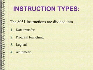
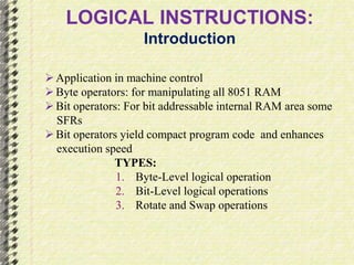
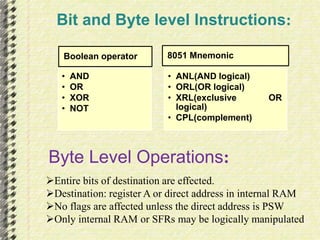
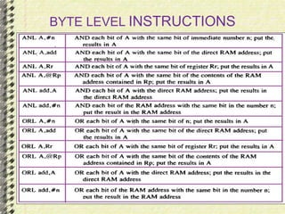
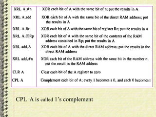
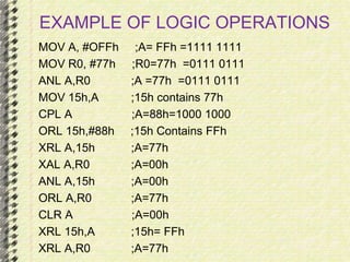
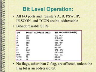
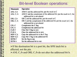
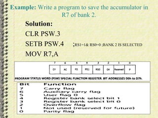
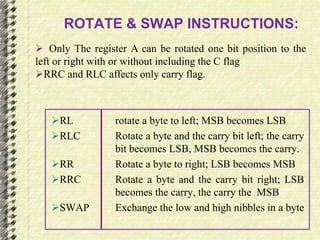
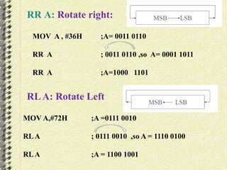
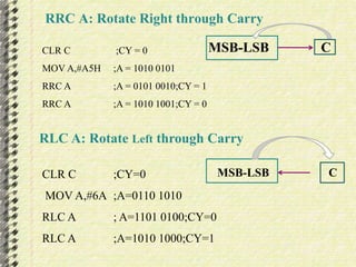
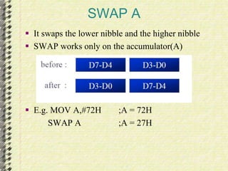
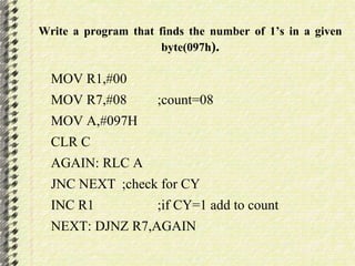
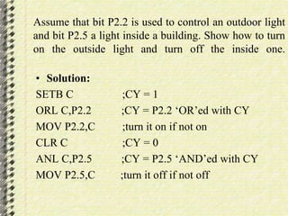
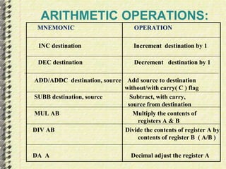
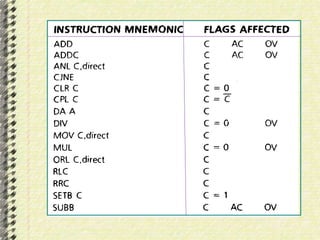
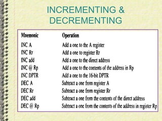
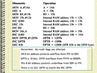
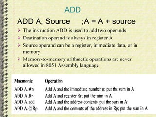
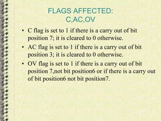
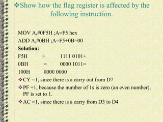
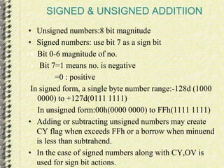
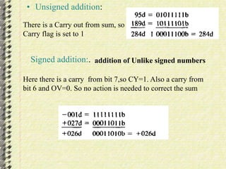
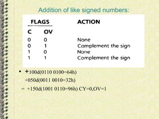
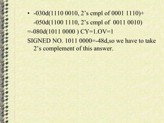
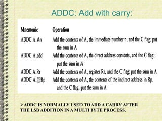
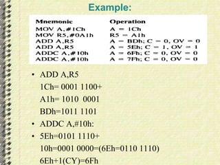
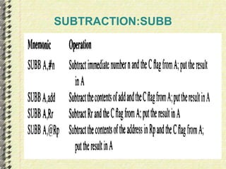
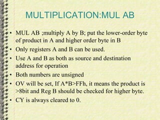
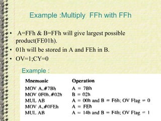
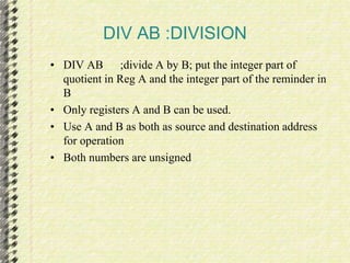
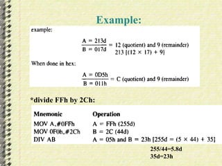
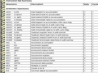
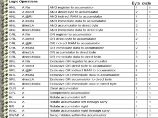
Presented by 
HEMANTH 
12MT06PED011 
ARITHMETIC 
AND 
LOGICAL 
OPERATIONS
INSTRUCTION TYPES: 
The 8051 instructions are divided into 
1. Data transfer 
2. Program branching 
3. Logical 
4. Arithmetic
LOGICAL INSTRUCTIONS: 
Introduction 
 Application in machine control 
 Byte operators: for manipulating all 8051 RAM 
 Bit operators: For bit addressable internal RAM area some 
SFRs 
 Bit operators yield compact program code and enhances 
execution speed 
TYPES: 
1. Byte-Level logical operation 
2. Bit-Level logical operations 
3. Rotate and Swap operations
Bit and Byte level Instructions: 
Boolean operator 
• AND 
• OR 
• XOR 
• NOT 
8051 Mnemonic 
• ANL(AND logical) 
• ORL(OR logical) 
• XRL(exclusive OR 
logical) 
• CPL(complement) 
Byte Level Operations: 
Entire bits of destination are effected. 
Destination: register A or direct address in internal RAM 
No flags are affected unless the direct address is PSW 
Only internal RAM or SFRs may be logically manipulated
BYTE LEVEL INSTRUCTIONS
CPL A is called 1’s complement
EXAMPLE OF LOGIC OPERATIONS 
MOV A, #OFFh ;A= FFh =1111 1111 
MOV R0, #77h ;R0=77h =0111 0111 
ANL A,R0 ;A =77h =0111 0111 
MOV 15h,A ;15h contains 77h 
CPL A ;A=88h=1000 1000 
ORL 15h,#88h ;15h Contains FFh 
XRL A,15h ;A=77h 
XAL A,R0 ;A=00h 
ANL A,15h ;A=00h 
ORL A,R0 ;A=77h 
CLR A ;A=00h 
XRL 15h,A ;15h= FFh 
XRL A,R0 ;A=77h
Bit Level Operation: 
• All I/O ports and registers A, B, PSW, IP, 
IE,SCON, and TCON are bit-addressable 
• Bit-addressable SFRs: 
• No flags, other than C flag, are affected, unless the 
flag bit is an addressed bit.
Bit-level Boolean operations: 
If the destination bit is a port bit, the SFR latch bit is 
affected, not the pin. 
ANL C,/b and ORL C,/b do not alter the addressed bit b.
Example: Write a program to save the accumulator in 
R7 of bank 2. 
Solution: 
CLR PSW.3 
SETB PSW.4 ;RS1=1& RS0=0 ;BANK 2 IS SELECTED 
MOV R7,A
ROTATE & SWAP INSTRUCTIONS: 
 Only The register A can be rotated one bit position to the 
left or right with or without including the C flag 
RRC and RLC affects only carry flag. 
RL rotate a byte to left; MSB becomes LSB 
RLC Rotate a byte and the carry bit left; the carry 
bit becomes LSB, MSB becomes the carry. 
RR Rotate a byte to right; LSB becomes MSB 
RRC Rotate a byte and the carry bit right; LSB 
becomes the carry, the carry the MSB 
SWAP Exchange the low and high nibbles in a byte
RR A: Rotate right: 
MOV A , #36H ;A= 0011 0110 
RR A ; 0011 0110 ,so A= 0001 1011 
RR A ;A=1000 1101 
RL A: Rotate Left 
MOV A,#72H ;A =0111 0010 
RL A ; 0111 0010 ,so A = 1110 0100 
RL A ;A = 1100 1001
RRC A: Rotate Right through Carry 
CLR C ;CY = 0 MSB-LSB C 
MOV A,#A5H ;A = 1010 0101 
RRC A ;A = 0101 0010;CY = 1 
RRC A ;A = 1010 1001;CY = 0 
RLC A: Rotate Left through Carry 
CLR C ;CY=0 
MOV A,#6A ;A=0110 1010 
RLC A ; A=1101 0100;CY=0 
RLC A ;A=1010 1000;CY=1 
MSB-LSB C
SWAP A 
 It swaps the lower nibble and the higher nibble 
 SWAP works only on the accumulator(A) 
 E.g. MOV A,#72H ;A = 72H 
SWAP A ;A = 27H
Write a program that finds the number of 1’s in a given 
byte(097h). 
MOV R1,#00 
MOV R7,#08 ;count=08 
MOV A,#097H 
CLR C 
AGAIN: RLC A 
JNC NEXT ;check for CY 
INC R1 ;if CY=1 add to count 
NEXT: DJNZ R7,AGAIN
Assume that bit P2.2 is used to control an outdoor light 
and bit P2.5 a light inside a building. Show how to turn 
on the outside light and turn off the inside one. 
• Solution: 
SETB C ;CY = 1 
ORL C,P2.2 ;CY = P2.2 ‘OR’ed with CY 
MOV P2.2,C ;turn it on if not on 
CLR C ;CY = 0 
ANL C,P2.5 ;CY = P2.5 ‘AND’ed with CY 
MOV P2.5,C ;turn it off if not off
ARITHMETIC OPERATIONS: 
MNEMONIC OPERATION 
INC destination Increment destination by 1 
DEC destination Decrement destination by 1 
ADD/ADDC destination, source Add source to destination 
without/with carry( C ) flag 
SUBB destination, source Subtract, with carry, 
source from destination 
MUL AB Multiply the contents of 
registers A & B 
DIV AB Divide the contents of register A by 
contents of register B ( A/B ) 
DA A Decimal adjust the register A
INCREMENTING & 
DECREMENTING
ADD 
ADD A, Source ;A = A + source 
 The instruction ADD is used to add two operands 
 Destination operand is always in register A 
 Source operand can be a register, immediate data, or in 
memory 
 Memory-to-memory arithmetic operations are never 
allowed in 8051 Assembly language
FLAGS AFFECTED: 
C,AC,OV 
• C flag is set to 1 if there is a carry out of bit 
position 7; it is cleared to 0 otherwise. 
• AC flag is set to 1 if there is a carry out of bit 
position 3; it is cleared to 0 otherwise. 
• OV flag is set to 1 if there is a carry out of bit 
position 7,not bit position6 or if there is a carry out 
of bit position6 not bit position7.
Show how the flag register is affected by the 
following instruction. 
MOV A,#0F5H ;A=F5 hex 
ADD A,#0BH ;A=F5+0B=00 
Solution: 
F5H + 1111 0101+ 
0BH = 0000 1011= 
100H 0000 0000 
CY =1, since there is a carry out from D7 
PF =1, because the number of 1s is zero (an even number), 
PF is set to 1. 
AC =1, since there is a carry from D3 to D4
SIGNED & UNSIGNED ADDITIION 
• Unsigned numbers:8 bit magnitude 
• Signed numbers: use bit 7 as a sign bit 
 Bit 0-6 magnitude of no. 
 Bit 7=1 means no. is negative 
=0 : positive 
In signed form, a single byte number range:-128d (1000 
0000) to +127d(0111 1111) 
In unsigned form:00h(0000 0000) to FFh(1111 1111) 
• Adding or subtracting unsigned numbers may create 
CY flag when exceeds FFh or a borrow when minuend 
is less than subtrahend. 
• In the case of signed numbers along with CY,OV is 
used for sign bit actions.
• Unsigned addition: 
There is a Carry out from sum, so 
Carry flag is set to 1 
Signed addition:. addition of Unlike signed numbers 
Here there is a carry from bit 7,so CY=1. Also a carry from 
bit 6 and OV=0. So no action is needed to correct the sum
Addition of like signed numbers: 
• +100d(0110 0100=64h) 
+050d(0011 0010=32h) 
= +150d(1001 0110=96h) CY=0,OV=1
• -030d(1110 0010, 2’s cmpl of 0001 1110)+ 
-050d(1100 1110, 2’s cmpl of 0011 0010) 
=-080d(1011 0000 ) CY=1.OV=1 
SIGNED NO. 1011 0000=-48d,so we have to take 
2’s complement of this answer.
ADDC: Add with carry: 
ADDC IS NORMALLY USED TO ADD A CARRY AFTER 
THE LSB ADDITION IN A MULTI BYTE PROCESS.
• ADD A,R5 
Example: 
1Ch= 0001 1100+ 
A1h= 1010 0001 
BDh=1011 1101 
• ADDC A,#10h: 
• 5Eh=0101 1110+ 
10h=0001 0000=(6Eh=0110 1110) 
6Eh+1(CY)=6Fh
SUBTRACTION:SUBB
MULTIPLICATION:MUL AB 
• MUL AB ;multiply A by B; put the lower-order byte 
of product in A and higher order byte in B 
• Only registers A and B can be used. 
• Use A and B as both as source and destination 
address for operation 
• Both numbers are unsigned 
• OV will be set, If A*B>FFh, it means the product is 
>8bit and Reg B should be checked for higher byte. 
• CY is always cleared to 0.
Example :Multiply FFh with FFh 
• A=FFh & B=FFh will give largest possible 
product(FE01h). 
• 01h will be stored in A and FEh in B. 
• OV=1;CY=0 
Example :
DIV AB :DIVISION 
• DIV AB ;divide A by B; put the integer part of 
quotient in Reg A and the integer part of the reminder in 
B 
• Only registers A and B can be used. 
• Use A and B as both as source and destination address 
for operation 
• Both numbers are unsigned
Example: 
*divide FFh by 2Ch: 
255/44=5.8d 
35d=23h
Byte cycle
Hemanth143

Hemanth143

  • 1.
    Presented by HEMANTH 12MT06PED011 ARITHMETIC AND LOGICAL OPERATIONS
  • 2.
    INSTRUCTION TYPES: The8051 instructions are divided into 1. Data transfer 2. Program branching 3. Logical 4. Arithmetic
  • 3.
    LOGICAL INSTRUCTIONS: Introduction  Application in machine control  Byte operators: for manipulating all 8051 RAM  Bit operators: For bit addressable internal RAM area some SFRs  Bit operators yield compact program code and enhances execution speed TYPES: 1. Byte-Level logical operation 2. Bit-Level logical operations 3. Rotate and Swap operations
  • 4.
    Bit and Bytelevel Instructions: Boolean operator • AND • OR • XOR • NOT 8051 Mnemonic • ANL(AND logical) • ORL(OR logical) • XRL(exclusive OR logical) • CPL(complement) Byte Level Operations: Entire bits of destination are effected. Destination: register A or direct address in internal RAM No flags are affected unless the direct address is PSW Only internal RAM or SFRs may be logically manipulated
  • 5.
  • 6.
    CPL A iscalled 1’s complement
  • 7.
    EXAMPLE OF LOGICOPERATIONS MOV A, #OFFh ;A= FFh =1111 1111 MOV R0, #77h ;R0=77h =0111 0111 ANL A,R0 ;A =77h =0111 0111 MOV 15h,A ;15h contains 77h CPL A ;A=88h=1000 1000 ORL 15h,#88h ;15h Contains FFh XRL A,15h ;A=77h XAL A,R0 ;A=00h ANL A,15h ;A=00h ORL A,R0 ;A=77h CLR A ;A=00h XRL 15h,A ;15h= FFh XRL A,R0 ;A=77h
  • 8.
    Bit Level Operation: • All I/O ports and registers A, B, PSW, IP, IE,SCON, and TCON are bit-addressable • Bit-addressable SFRs: • No flags, other than C flag, are affected, unless the flag bit is an addressed bit.
  • 9.
    Bit-level Boolean operations: If the destination bit is a port bit, the SFR latch bit is affected, not the pin. ANL C,/b and ORL C,/b do not alter the addressed bit b.
  • 10.
    Example: Write aprogram to save the accumulator in R7 of bank 2. Solution: CLR PSW.3 SETB PSW.4 ;RS1=1& RS0=0 ;BANK 2 IS SELECTED MOV R7,A
  • 11.
    ROTATE & SWAPINSTRUCTIONS:  Only The register A can be rotated one bit position to the left or right with or without including the C flag RRC and RLC affects only carry flag. RL rotate a byte to left; MSB becomes LSB RLC Rotate a byte and the carry bit left; the carry bit becomes LSB, MSB becomes the carry. RR Rotate a byte to right; LSB becomes MSB RRC Rotate a byte and the carry bit right; LSB becomes the carry, the carry the MSB SWAP Exchange the low and high nibbles in a byte
  • 12.
    RR A: Rotateright: MOV A , #36H ;A= 0011 0110 RR A ; 0011 0110 ,so A= 0001 1011 RR A ;A=1000 1101 RL A: Rotate Left MOV A,#72H ;A =0111 0010 RL A ; 0111 0010 ,so A = 1110 0100 RL A ;A = 1100 1001
  • 13.
    RRC A: RotateRight through Carry CLR C ;CY = 0 MSB-LSB C MOV A,#A5H ;A = 1010 0101 RRC A ;A = 0101 0010;CY = 1 RRC A ;A = 1010 1001;CY = 0 RLC A: Rotate Left through Carry CLR C ;CY=0 MOV A,#6A ;A=0110 1010 RLC A ; A=1101 0100;CY=0 RLC A ;A=1010 1000;CY=1 MSB-LSB C
  • 14.
    SWAP A It swaps the lower nibble and the higher nibble  SWAP works only on the accumulator(A)  E.g. MOV A,#72H ;A = 72H SWAP A ;A = 27H
  • 15.
    Write a programthat finds the number of 1’s in a given byte(097h). MOV R1,#00 MOV R7,#08 ;count=08 MOV A,#097H CLR C AGAIN: RLC A JNC NEXT ;check for CY INC R1 ;if CY=1 add to count NEXT: DJNZ R7,AGAIN
  • 16.
    Assume that bitP2.2 is used to control an outdoor light and bit P2.5 a light inside a building. Show how to turn on the outside light and turn off the inside one. • Solution: SETB C ;CY = 1 ORL C,P2.2 ;CY = P2.2 ‘OR’ed with CY MOV P2.2,C ;turn it on if not on CLR C ;CY = 0 ANL C,P2.5 ;CY = P2.5 ‘AND’ed with CY MOV P2.5,C ;turn it off if not off
  • 17.
    ARITHMETIC OPERATIONS: MNEMONICOPERATION INC destination Increment destination by 1 DEC destination Decrement destination by 1 ADD/ADDC destination, source Add source to destination without/with carry( C ) flag SUBB destination, source Subtract, with carry, source from destination MUL AB Multiply the contents of registers A & B DIV AB Divide the contents of register A by contents of register B ( A/B ) DA A Decimal adjust the register A
  • 19.
  • 21.
    ADD ADD A,Source ;A = A + source  The instruction ADD is used to add two operands  Destination operand is always in register A  Source operand can be a register, immediate data, or in memory  Memory-to-memory arithmetic operations are never allowed in 8051 Assembly language
  • 22.
    FLAGS AFFECTED: C,AC,OV • C flag is set to 1 if there is a carry out of bit position 7; it is cleared to 0 otherwise. • AC flag is set to 1 if there is a carry out of bit position 3; it is cleared to 0 otherwise. • OV flag is set to 1 if there is a carry out of bit position 7,not bit position6 or if there is a carry out of bit position6 not bit position7.
  • 23.
    Show how theflag register is affected by the following instruction. MOV A,#0F5H ;A=F5 hex ADD A,#0BH ;A=F5+0B=00 Solution: F5H + 1111 0101+ 0BH = 0000 1011= 100H 0000 0000 CY =1, since there is a carry out from D7 PF =1, because the number of 1s is zero (an even number), PF is set to 1. AC =1, since there is a carry from D3 to D4
  • 24.
    SIGNED & UNSIGNEDADDITIION • Unsigned numbers:8 bit magnitude • Signed numbers: use bit 7 as a sign bit  Bit 0-6 magnitude of no.  Bit 7=1 means no. is negative =0 : positive In signed form, a single byte number range:-128d (1000 0000) to +127d(0111 1111) In unsigned form:00h(0000 0000) to FFh(1111 1111) • Adding or subtracting unsigned numbers may create CY flag when exceeds FFh or a borrow when minuend is less than subtrahend. • In the case of signed numbers along with CY,OV is used for sign bit actions.
  • 25.
    • Unsigned addition: There is a Carry out from sum, so Carry flag is set to 1 Signed addition:. addition of Unlike signed numbers Here there is a carry from bit 7,so CY=1. Also a carry from bit 6 and OV=0. So no action is needed to correct the sum
  • 26.
    Addition of likesigned numbers: • +100d(0110 0100=64h) +050d(0011 0010=32h) = +150d(1001 0110=96h) CY=0,OV=1
  • 27.
    • -030d(1110 0010,2’s cmpl of 0001 1110)+ -050d(1100 1110, 2’s cmpl of 0011 0010) =-080d(1011 0000 ) CY=1.OV=1 SIGNED NO. 1011 0000=-48d,so we have to take 2’s complement of this answer.
  • 28.
    ADDC: Add withcarry: ADDC IS NORMALLY USED TO ADD A CARRY AFTER THE LSB ADDITION IN A MULTI BYTE PROCESS.
  • 29.
    • ADD A,R5 Example: 1Ch= 0001 1100+ A1h= 1010 0001 BDh=1011 1101 • ADDC A,#10h: • 5Eh=0101 1110+ 10h=0001 0000=(6Eh=0110 1110) 6Eh+1(CY)=6Fh
  • 30.
  • 31.
    MULTIPLICATION:MUL AB •MUL AB ;multiply A by B; put the lower-order byte of product in A and higher order byte in B • Only registers A and B can be used. • Use A and B as both as source and destination address for operation • Both numbers are unsigned • OV will be set, If A*B>FFh, it means the product is >8bit and Reg B should be checked for higher byte. • CY is always cleared to 0.
  • 32.
    Example :Multiply FFhwith FFh • A=FFh & B=FFh will give largest possible product(FE01h). • 01h will be stored in A and FEh in B. • OV=1;CY=0 Example :
  • 33.
    DIV AB :DIVISION • DIV AB ;divide A by B; put the integer part of quotient in Reg A and the integer part of the reminder in B • Only registers A and B can be used. • Use A and B as both as source and destination address for operation • Both numbers are unsigned
  • 34.
    Example: *divide FFhby 2Ch: 255/44=5.8d 35d=23h
  • 36.