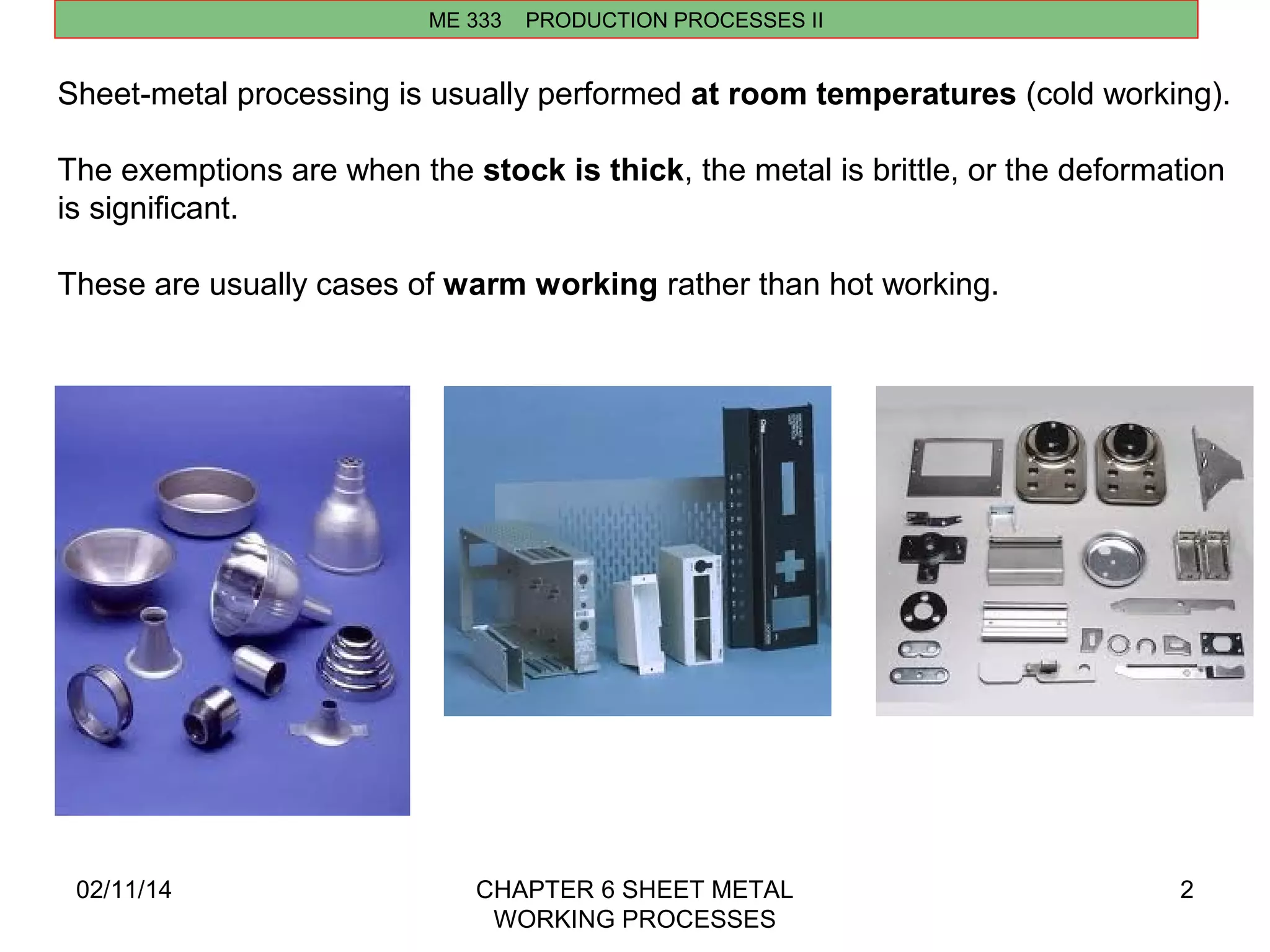
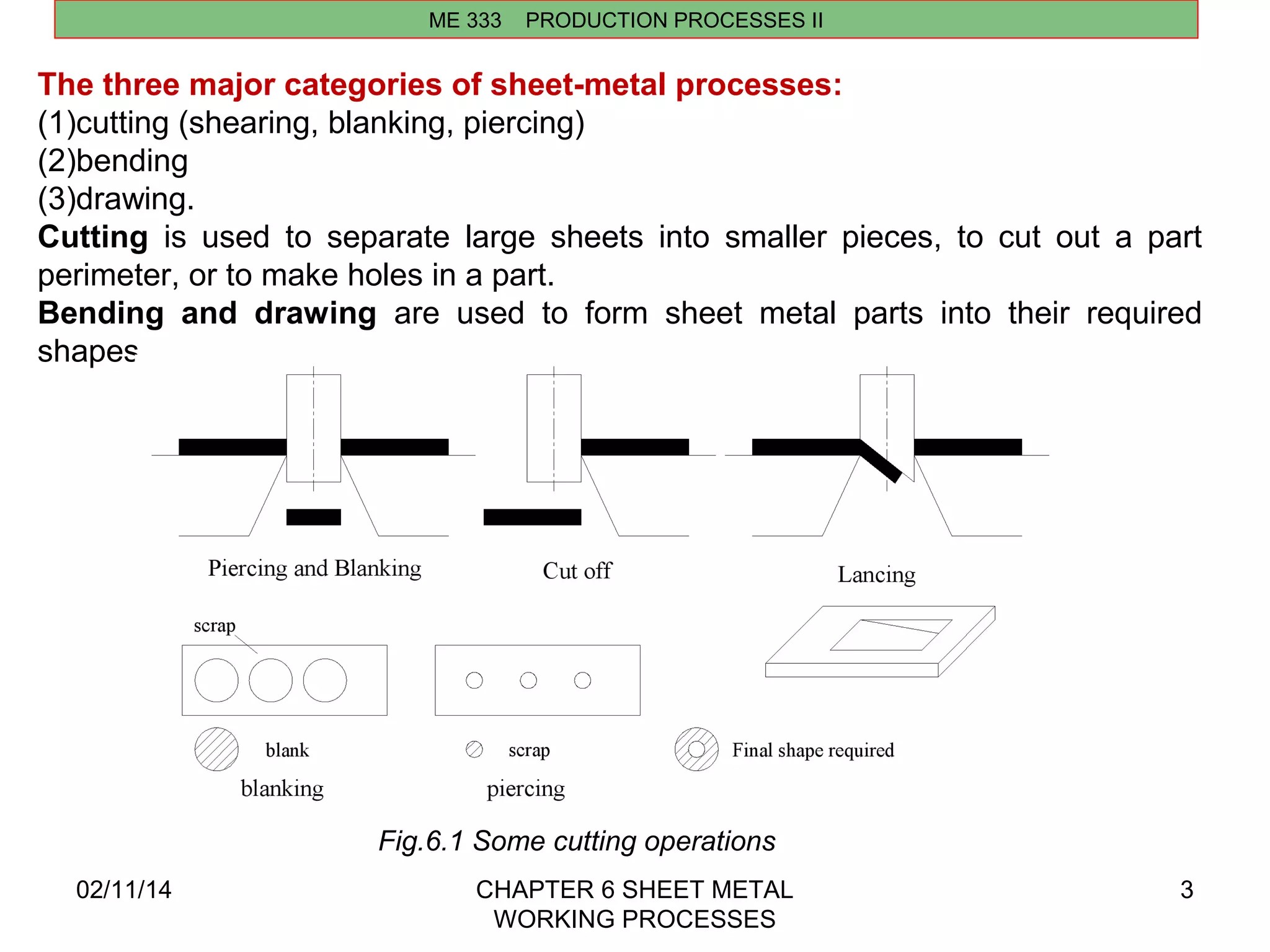
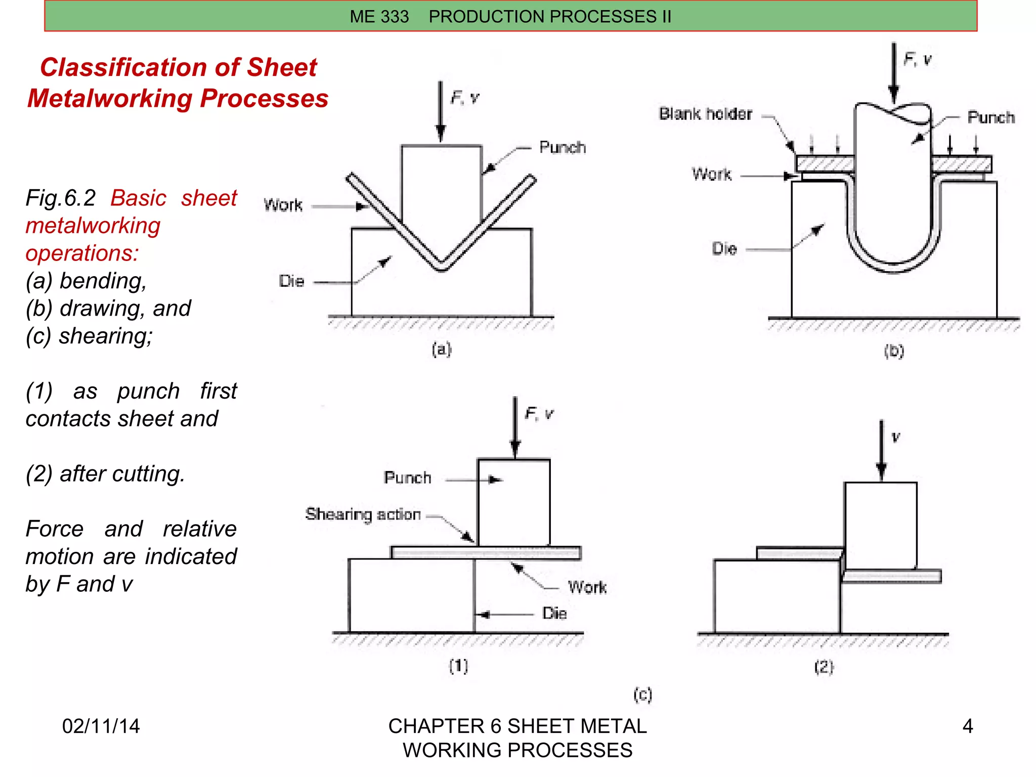
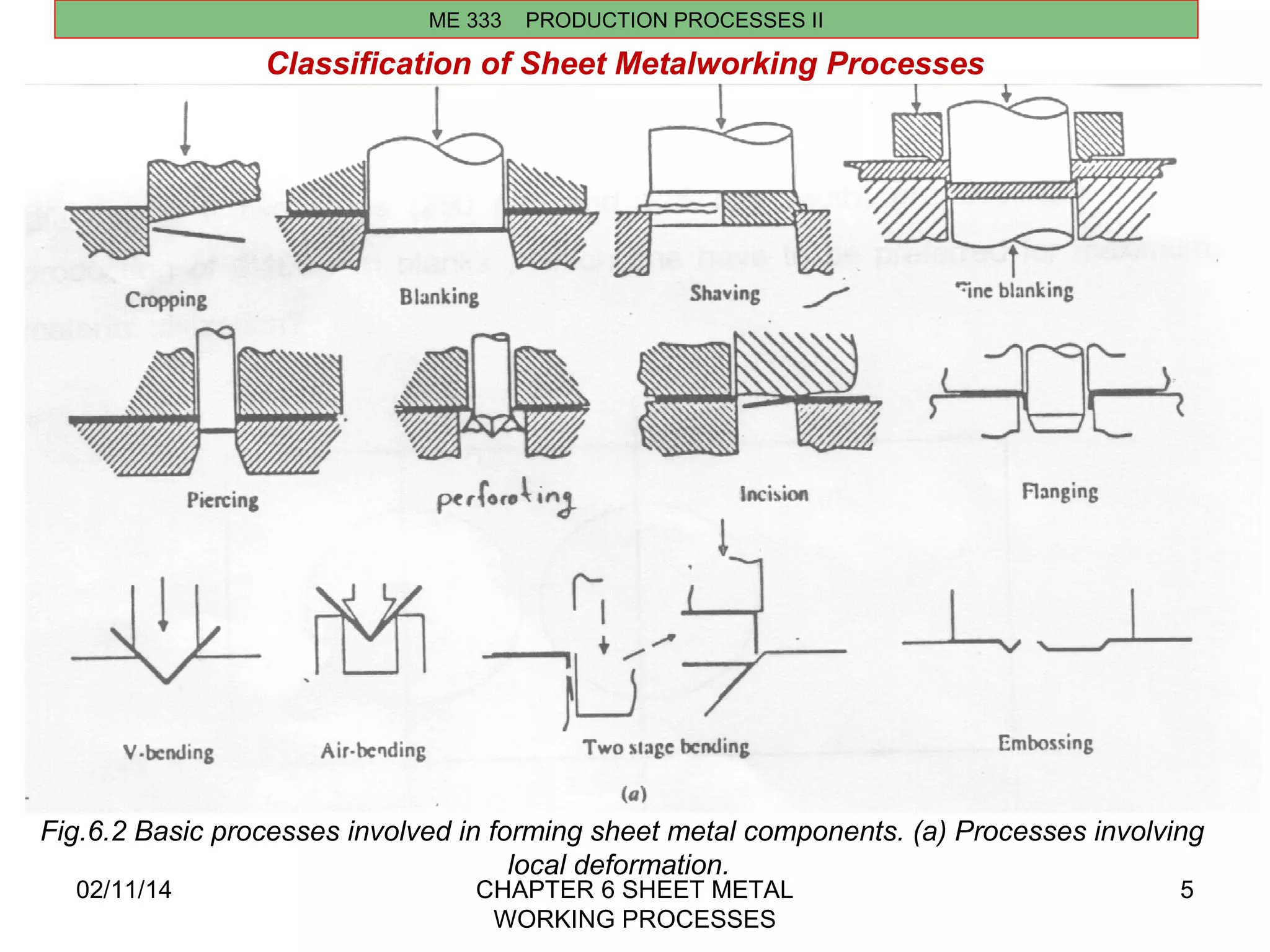
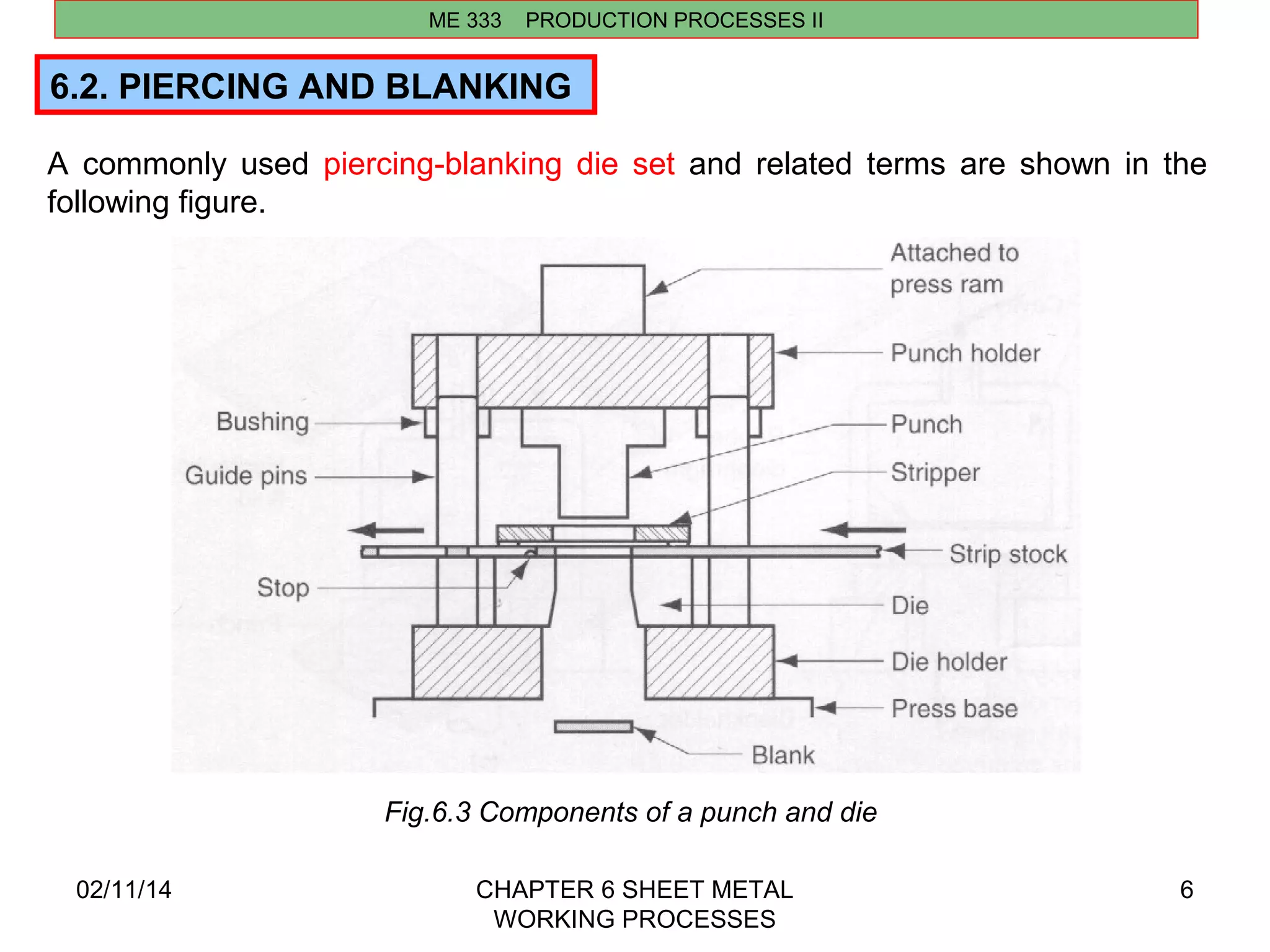
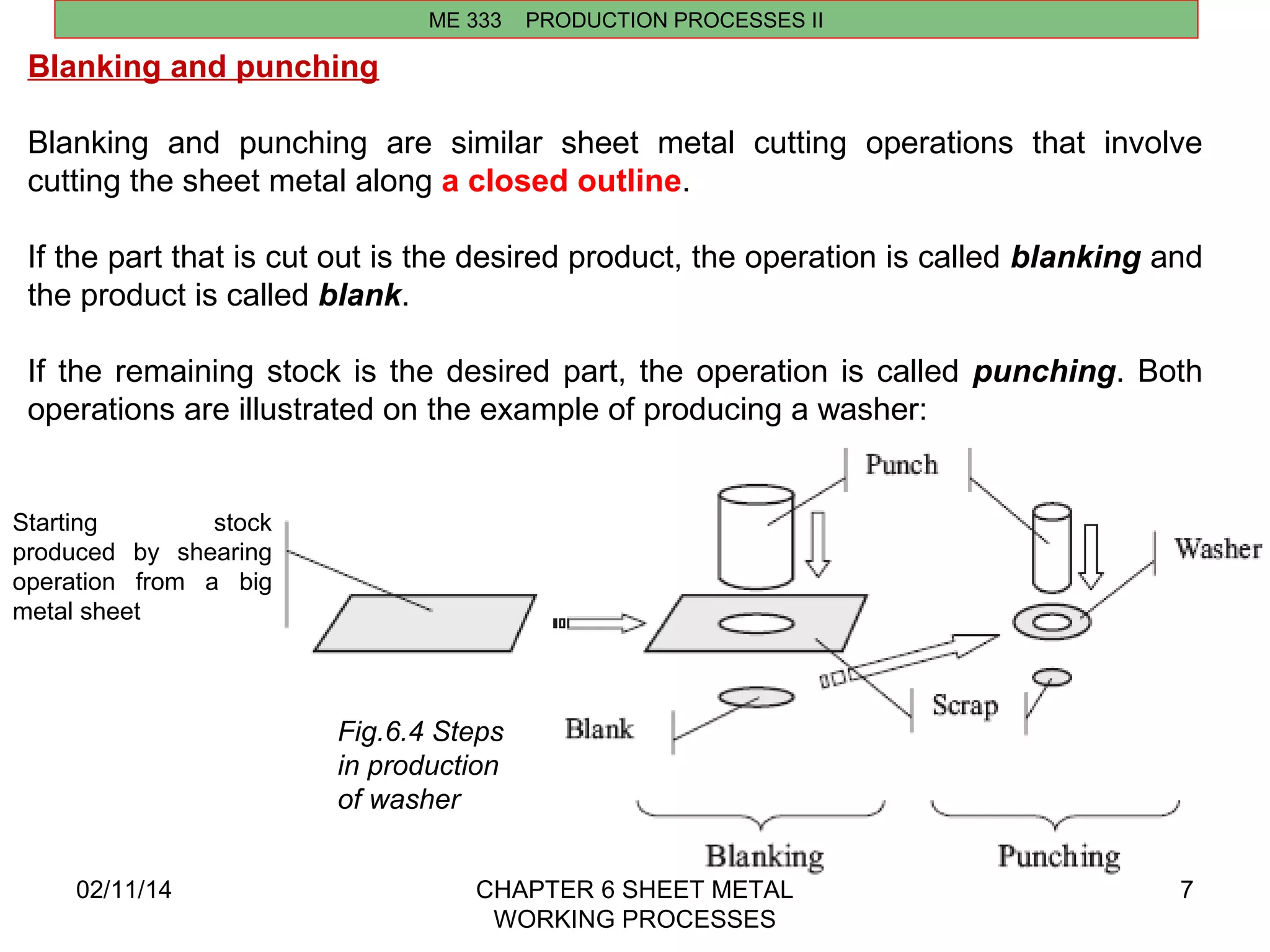
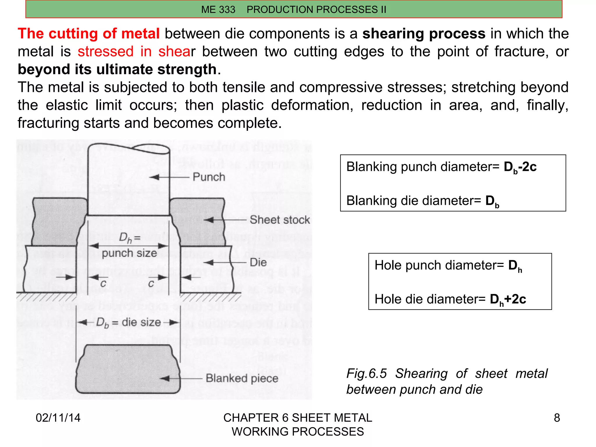
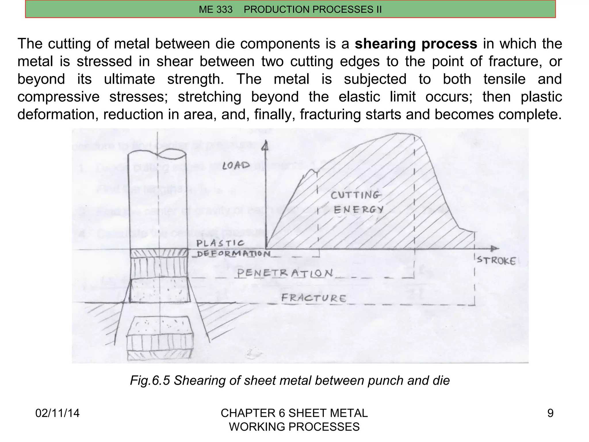
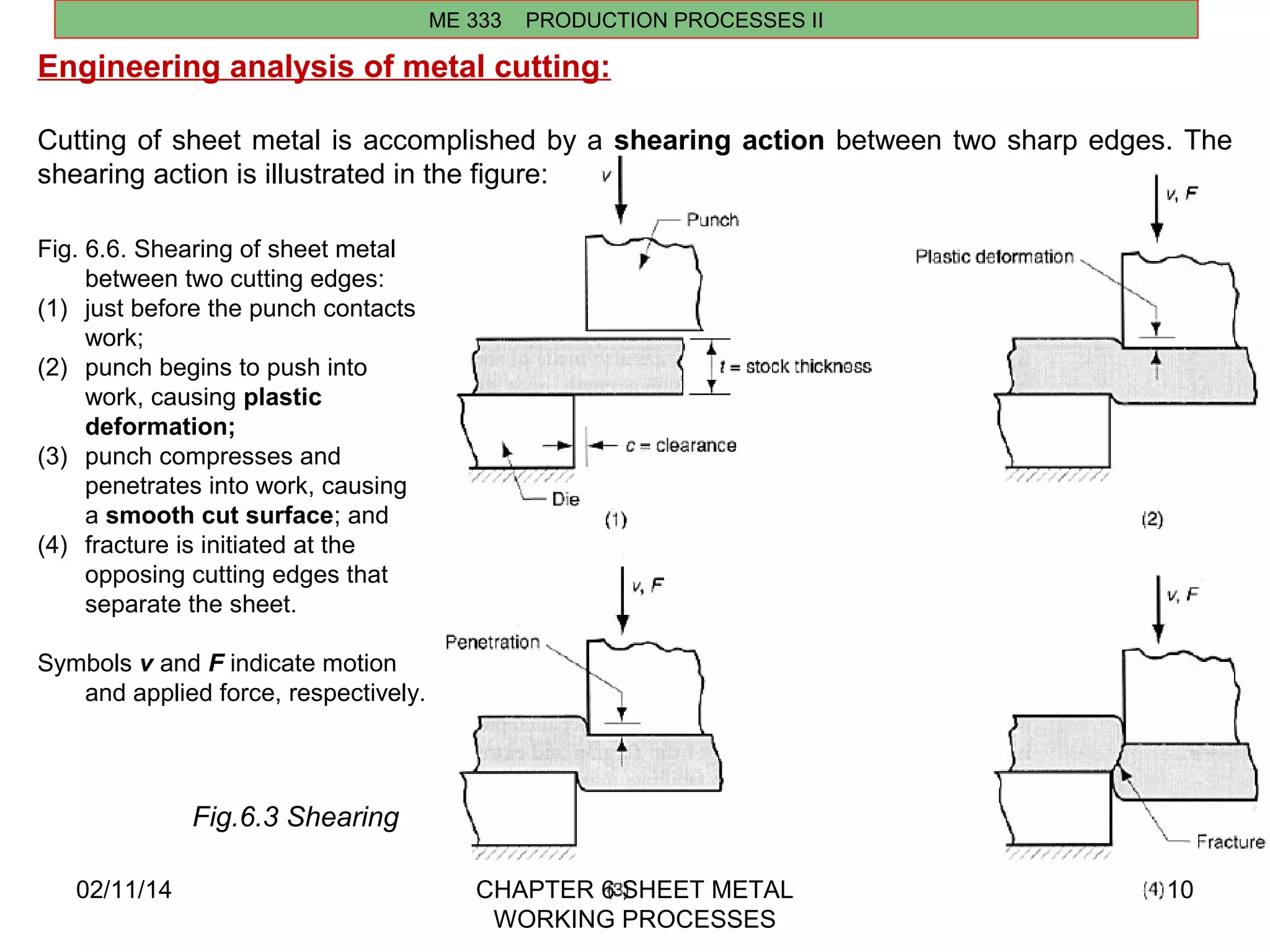
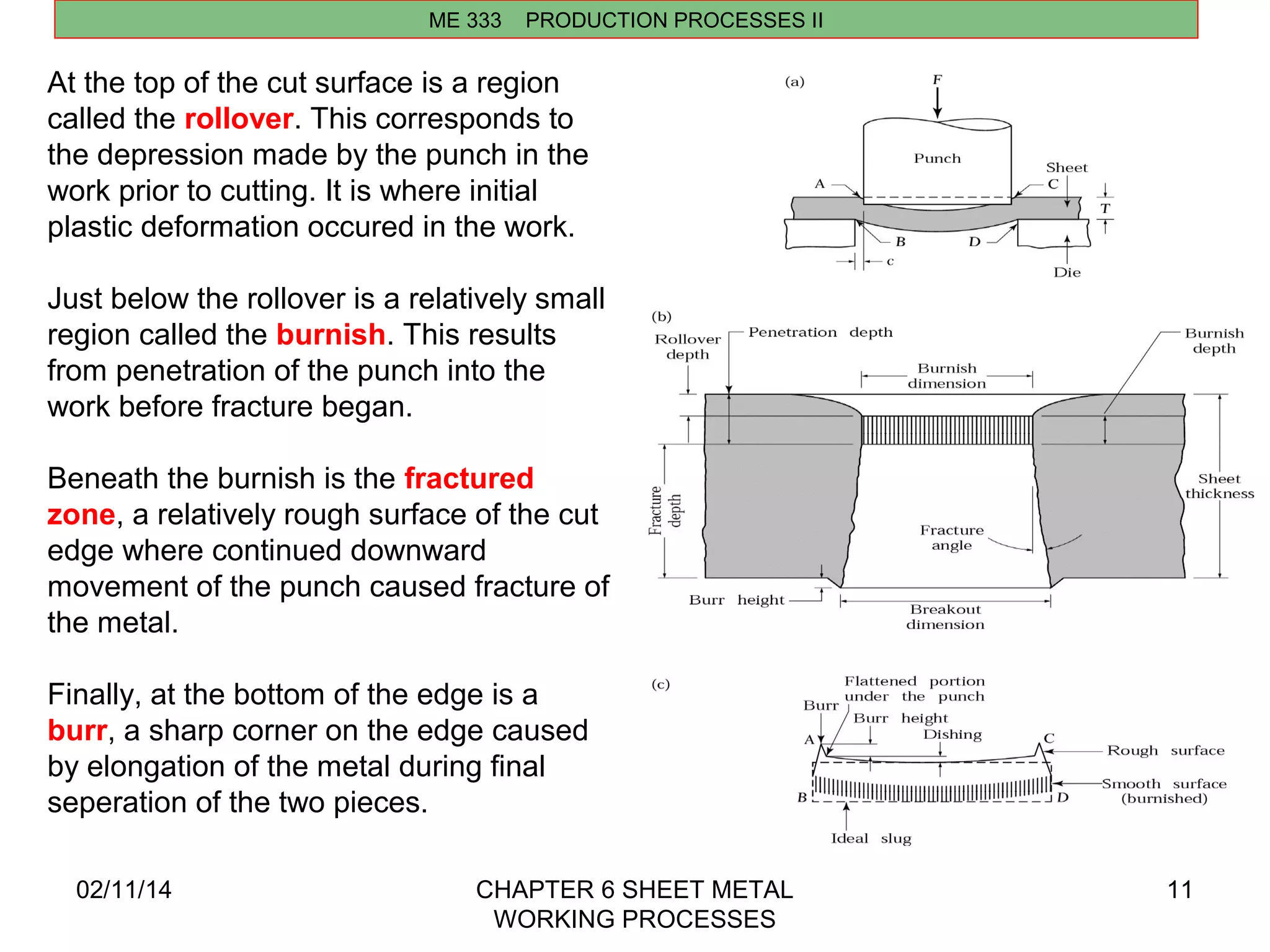
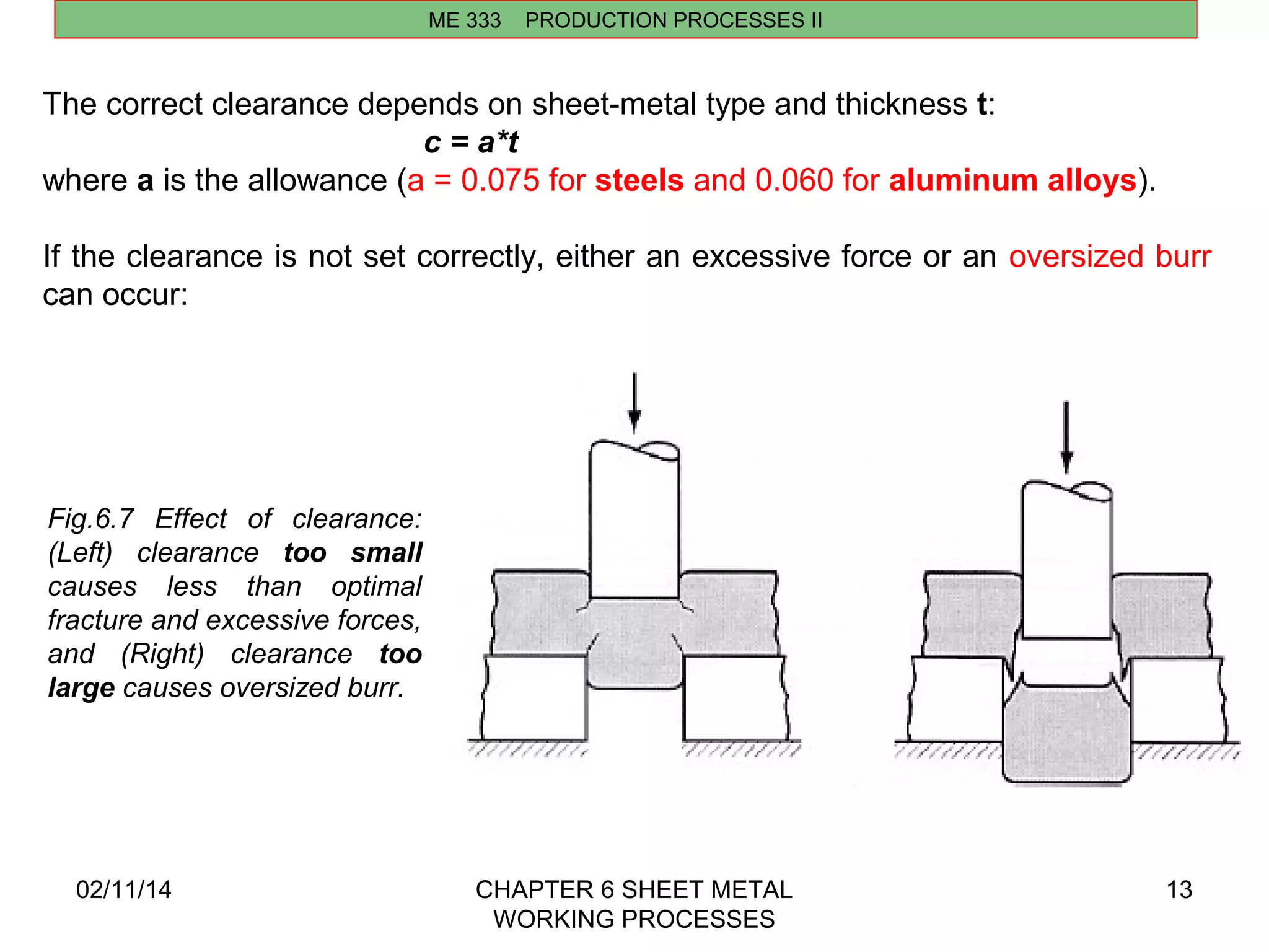
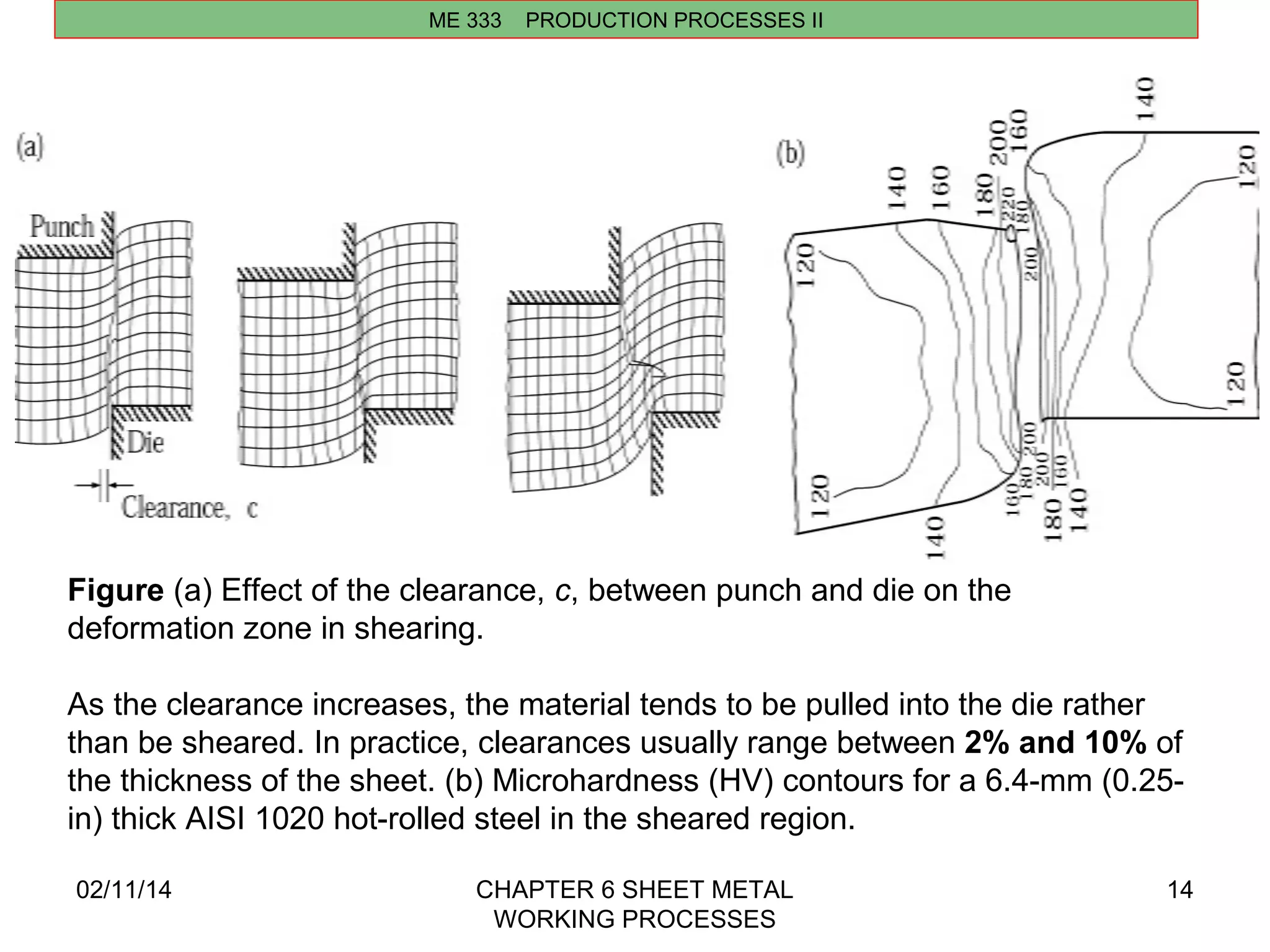
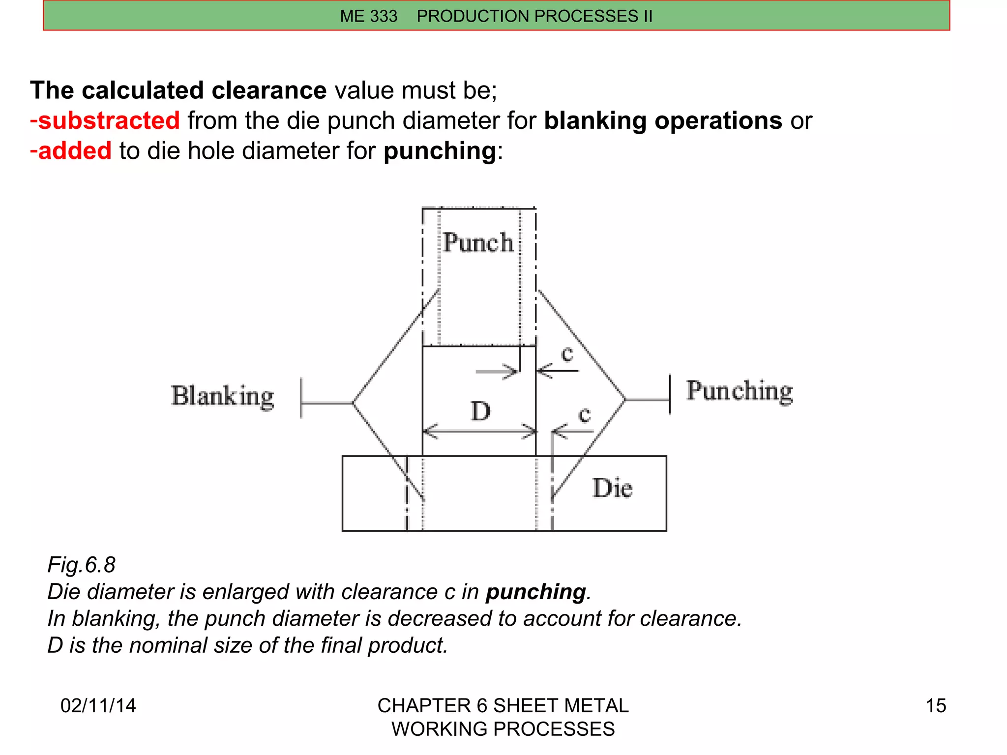
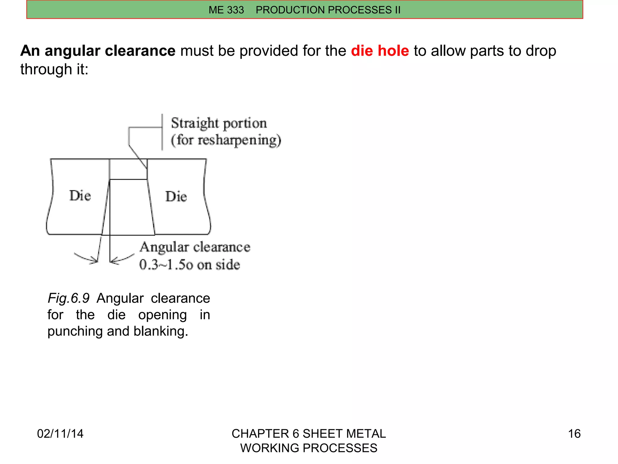
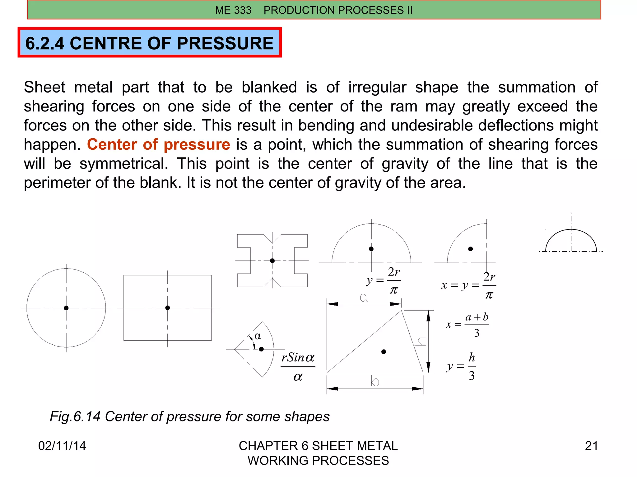
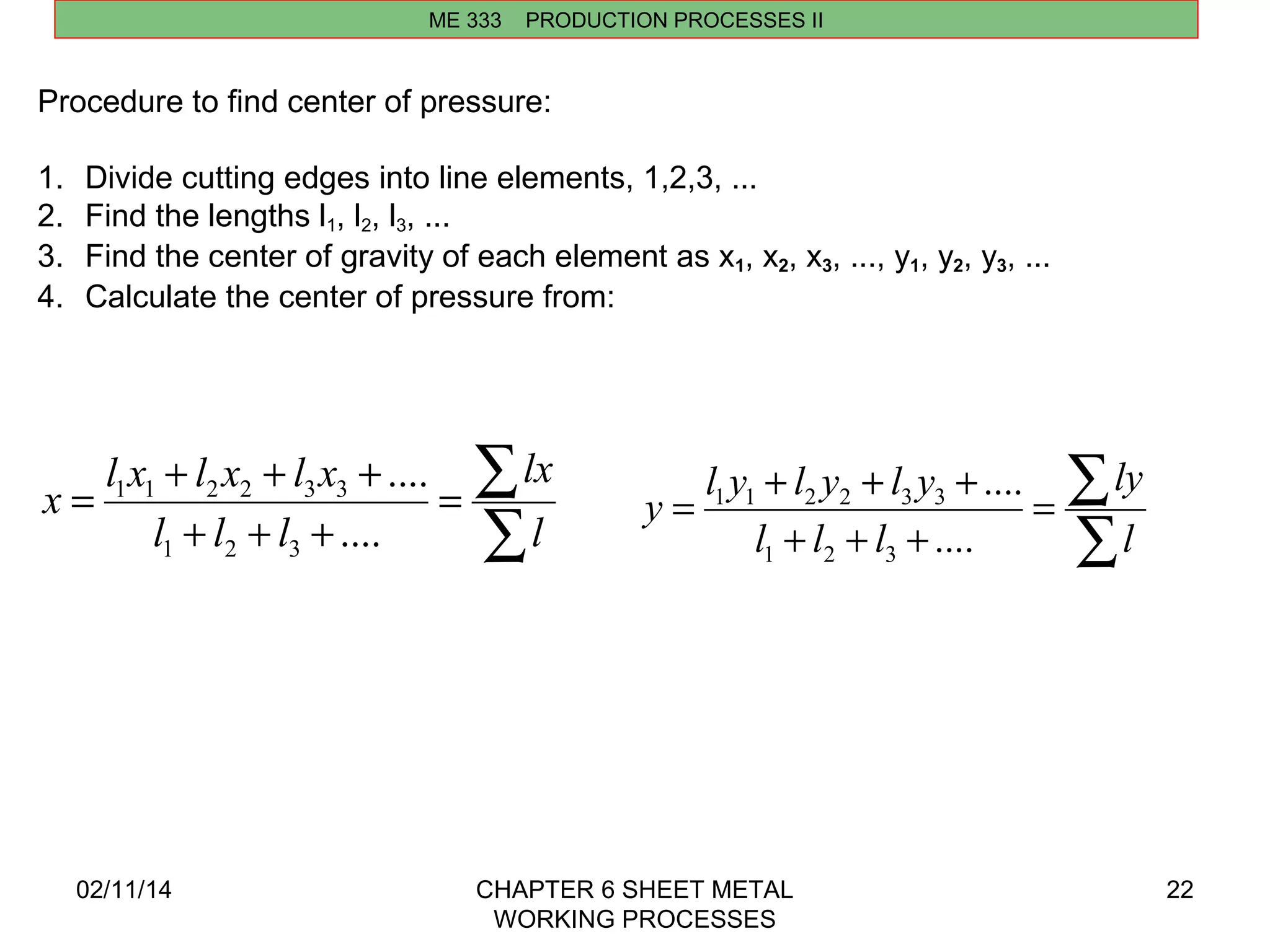
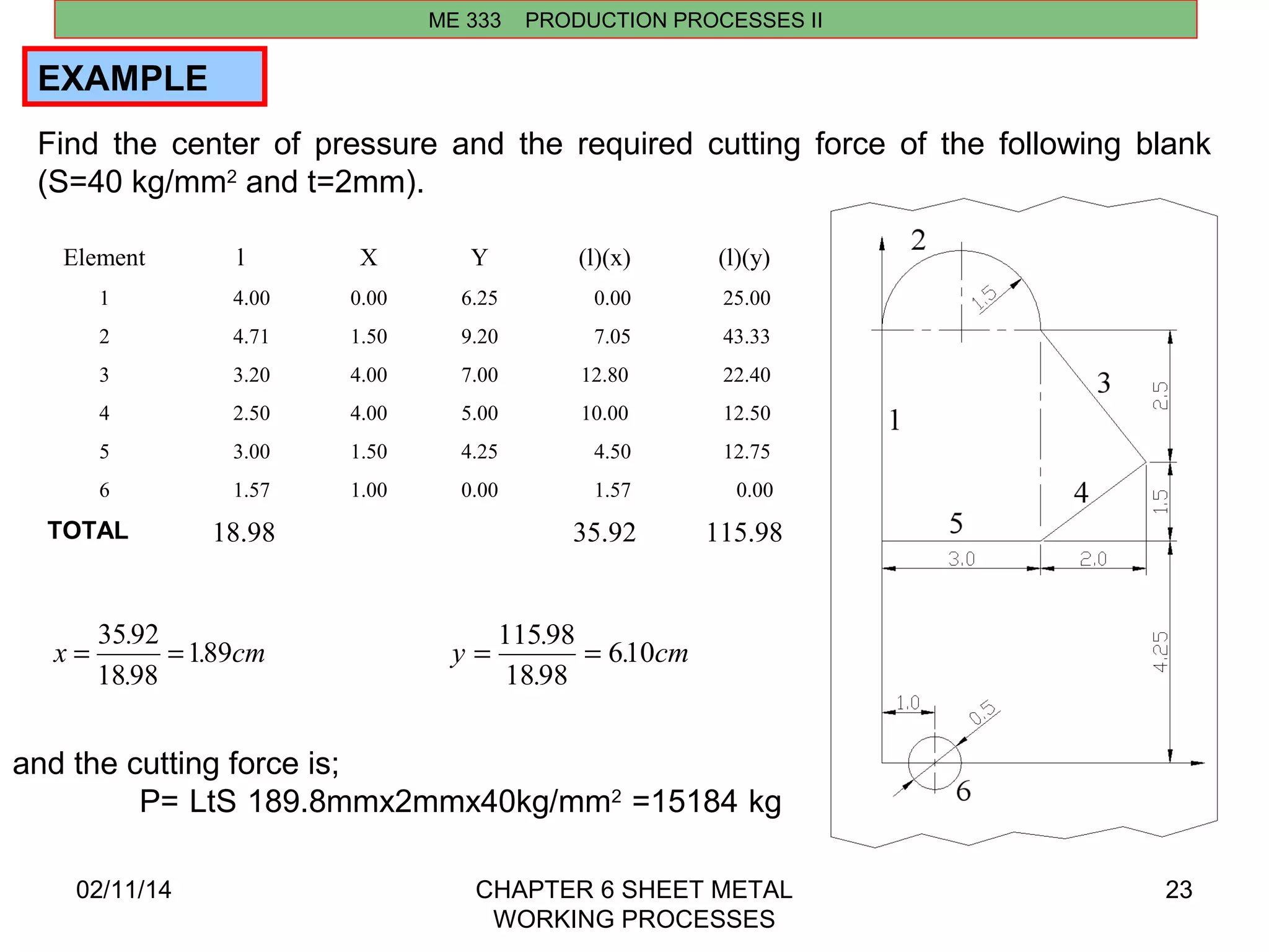
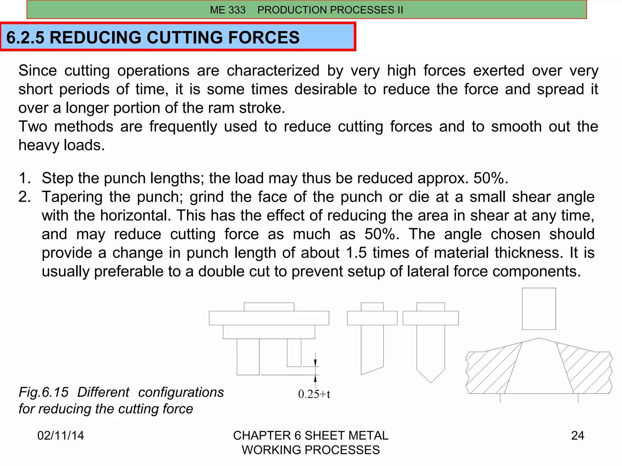
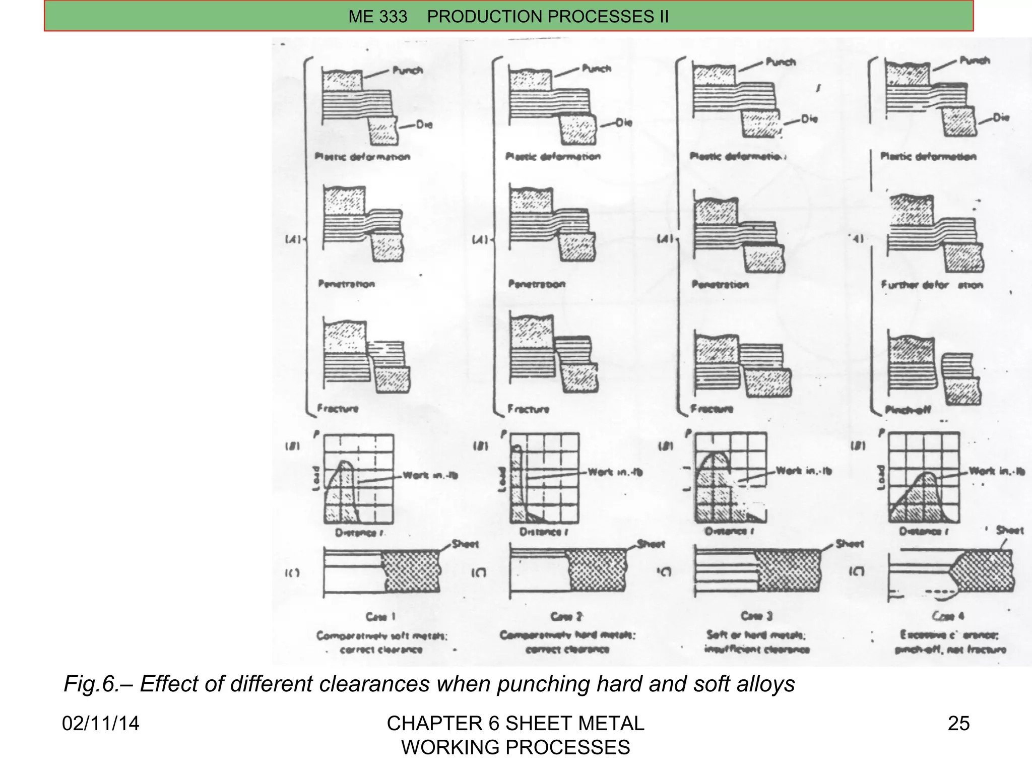
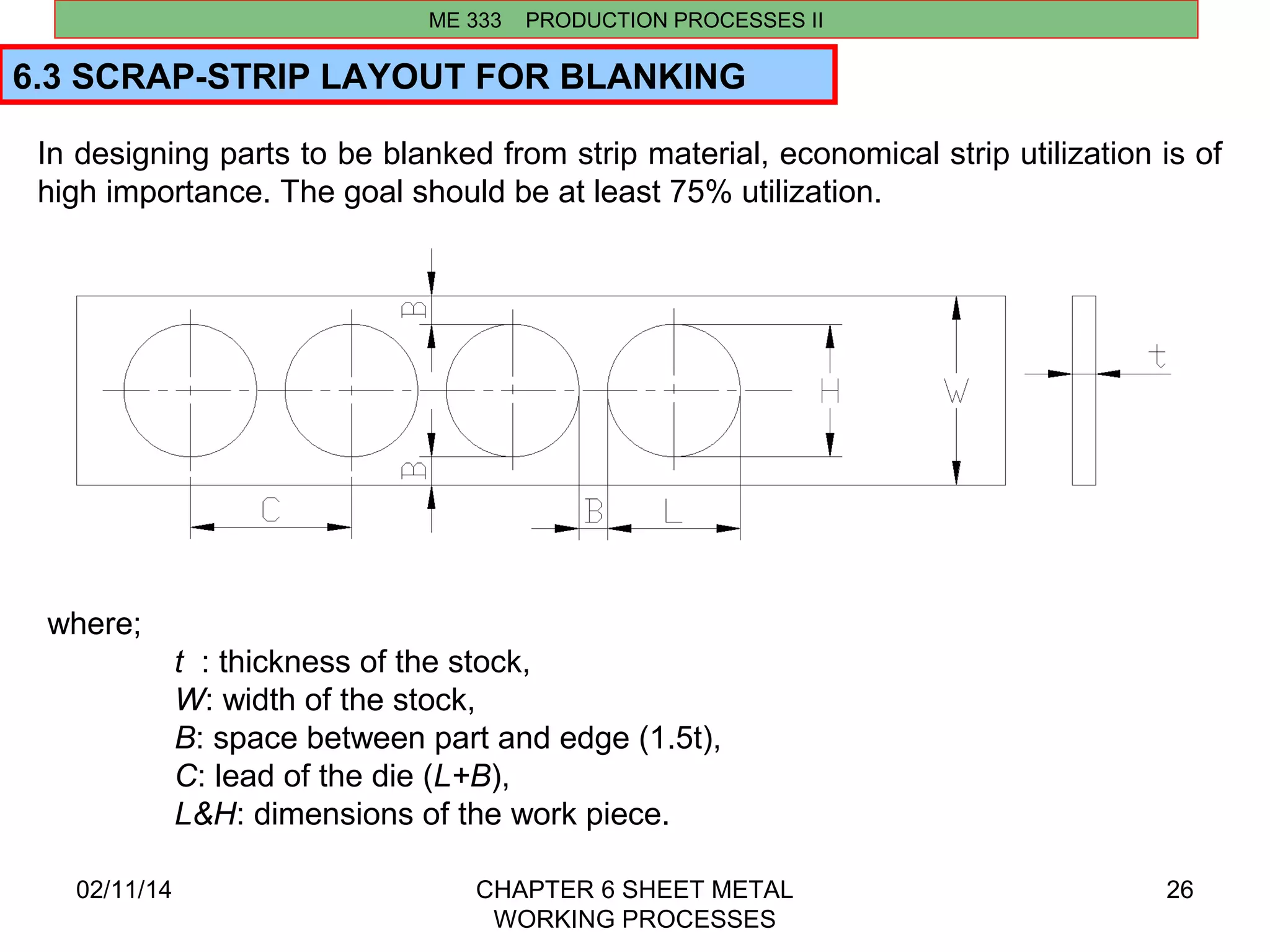
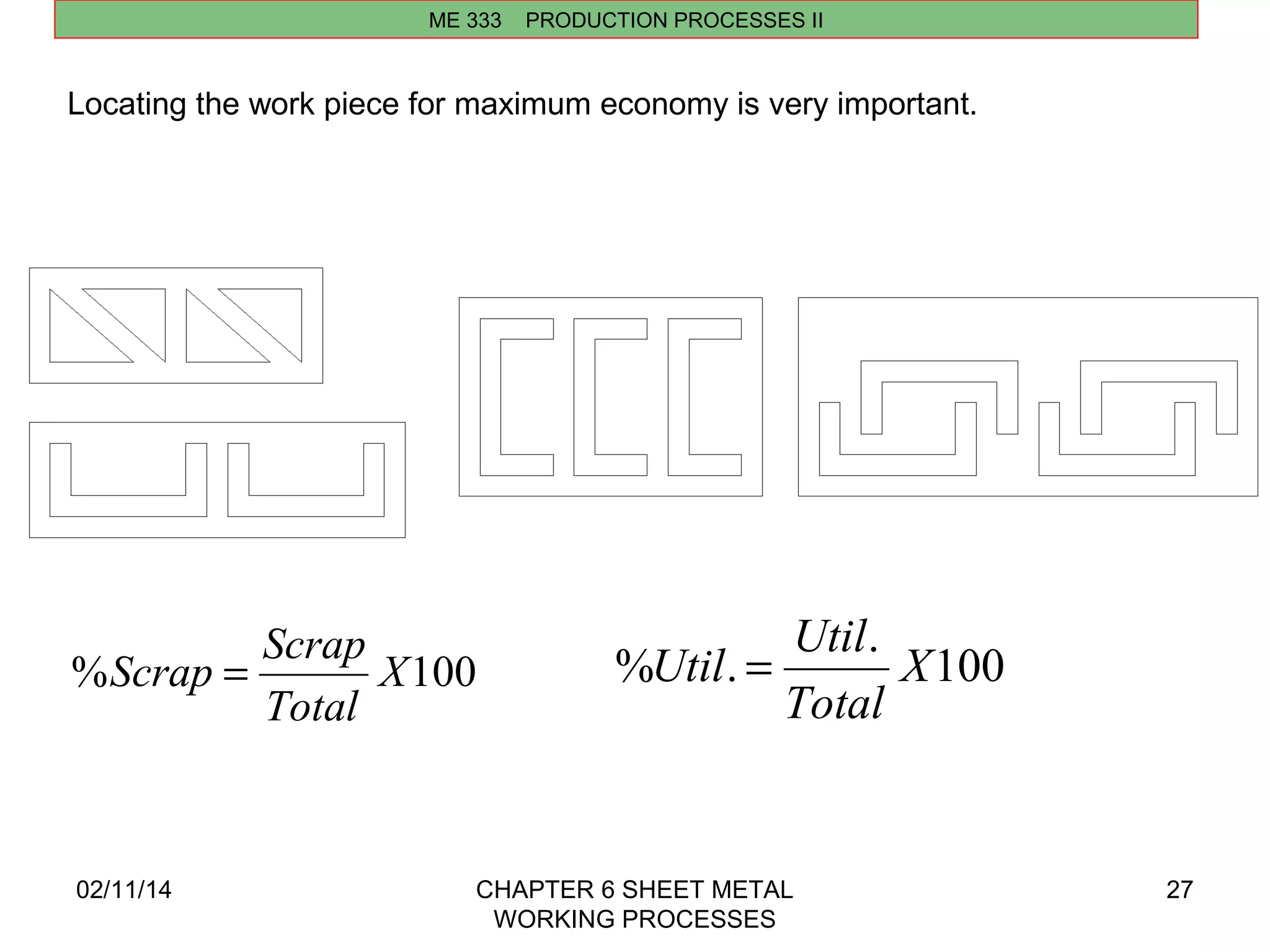
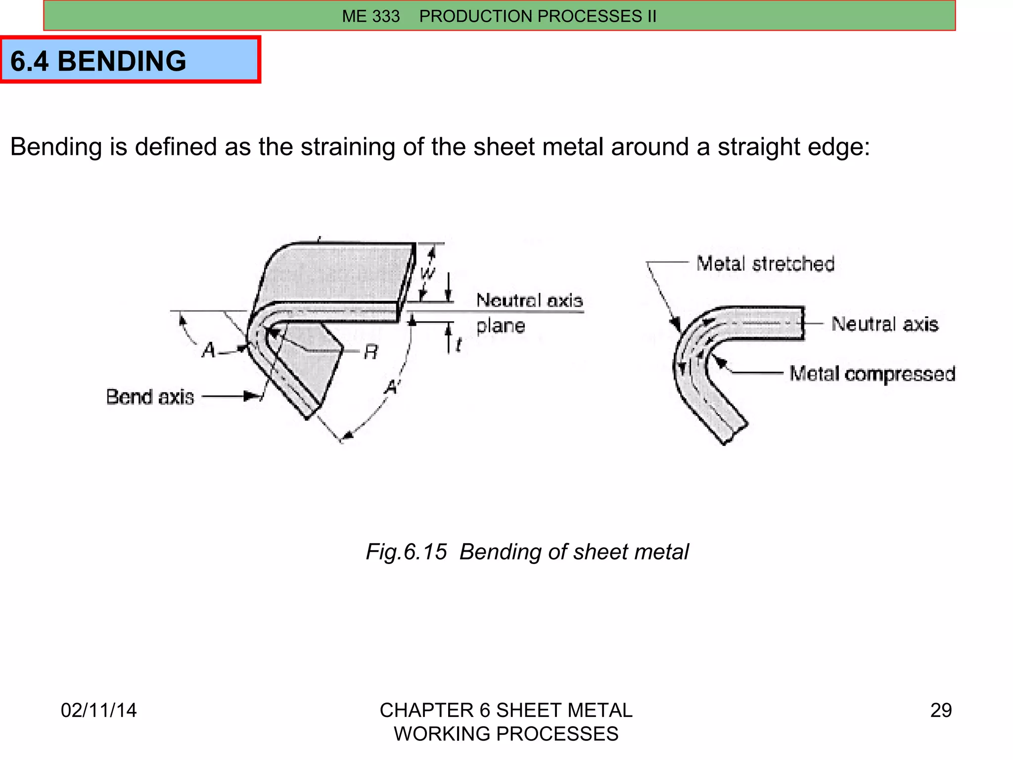
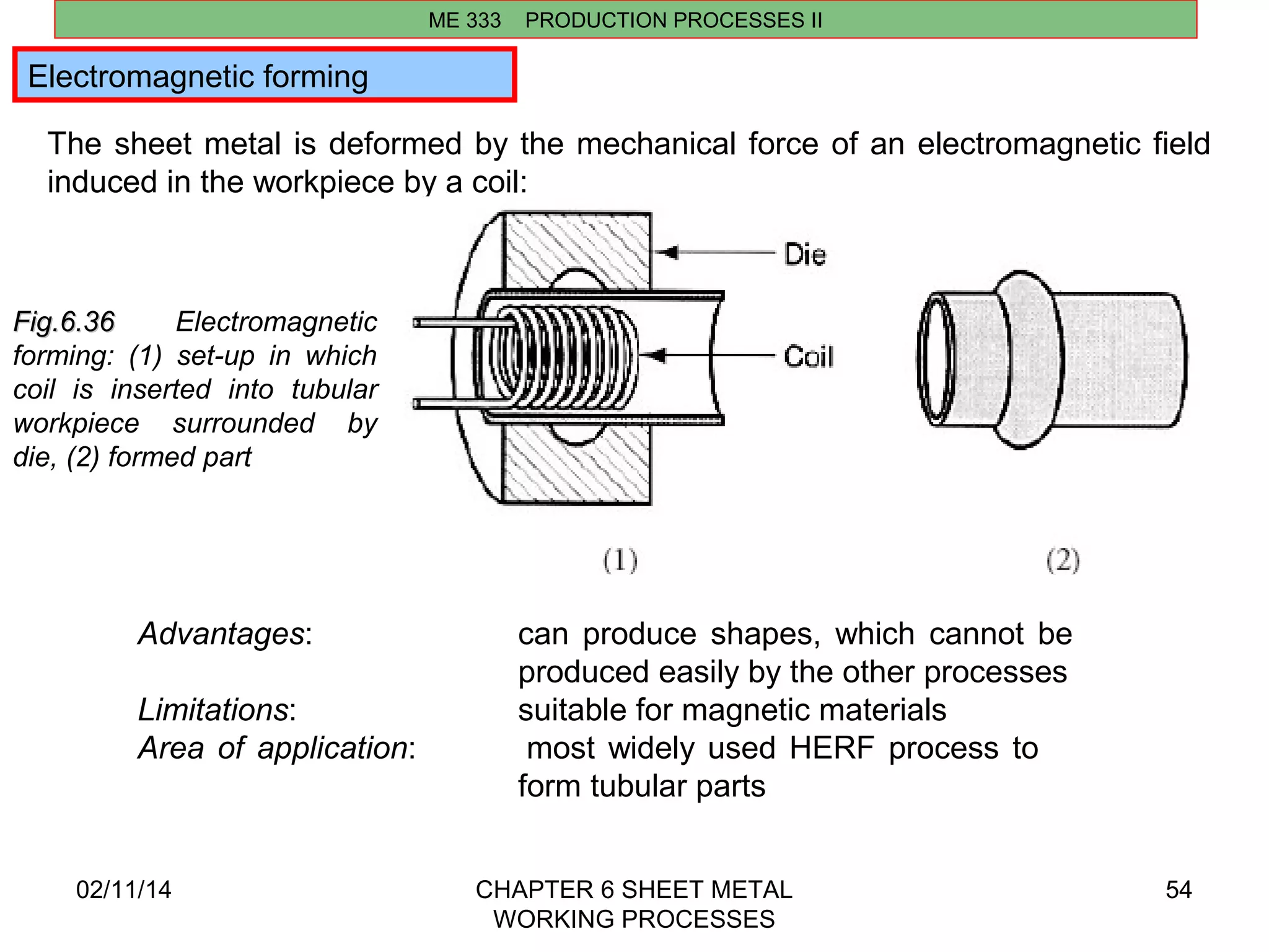
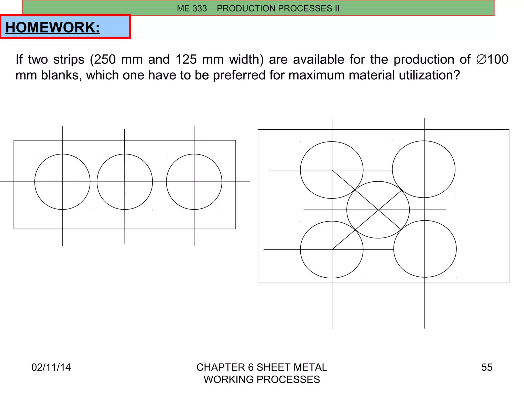
02/11/14 CHAPTER 6 SHEET METAL 
WORKING PROCESSES 
1 
CHAPTER 6 
SHEET METAL WORKING PROCESSES 
6.1 INTRODUCTION 
ME 333 PRODUCTION PROCESSES II 
Sheet metalworking includes cutting and forming operations performed on 
relatively thin sheets of metal (0.4-6 mm). 
The tooling used to perform sheet metalwork is called punch and die. Most sheet 
metal operations are performed on machine tools called presses. 
The term stamping press is used to distinguish these presses from forging and 
extrusion presses. The sheet metal products are called stampings. 
The commercial importance of sheet metalworking is significant. 
The number of consumer and industrial products that include sheet metal parts: 
automobile and truck bodies, airplanes, railway cars and locomotives, farm 
and construction equipment, small and large appliances, office furniture, 
computers and office equipment, and more. Sheet metal parts are generally 
characterized by high strength, good dimensional tolerances, good surface finish, 
and relatively low cost.
02/11/14 CHAPTER 6 SHEET METAL 
WORKING PROCESSES 
2 
ME 333 PRODUCTION PROCESSES II 
Sheet-metal processing is usually performed at room temperatures (cold working). 
The exemptions are when the stock is thick, the metal is brittle, or the deformation 
is significant. 
These are usually cases of warm working rather than hot working.
02/11/14 CHAPTER 6 SHEET METAL 
WORKING PROCESSES 
3 
ME 333 PRODUCTION PROCESSES II 
The three major categories of sheet-metal processes: 
(1)cutting (shearing, blanking, piercing) 
(2)bending 
(3)drawing. 
Cutting is used to separate large sheets into smaller pieces, to cut out a part 
perimeter, or to make holes in a part. 
Bending and drawing are used to form sheet metal parts into their required 
shapes. 
Fig.6.1 Some cutting operations
02/11/14 CHAPTER 6 SHEET METAL 
WORKING PROCESSES 
4 
ME 333 PRODUCTION PROCESSES II 
Classification of Sheet 
Metalworking Processes 
Fig.6.2 Basic sheet 
metalworking 
operations: 
(a) bending, 
(b) drawing, and 
(c) shearing; 
(1) as punch first 
contacts sheet and 
(2) after cutting. 
Force and relative 
motion are indicated 
by F and v
02/11/14 CHAPTER 6 SHEET METAL 
WORKING PROCESSES 
5 
ME 333 PRODUCTION PROCESSES II 
Classification of Sheet Metalworking Processes 
Fig.6.2 Basic processes involved in forming sheet metal components. (a) Processes involving 
local deformation.
02/11/14 CHAPTER 6 SHEET METAL 
WORKING PROCESSES 
6 
ME 333 PRODUCTION PROCESSES II 
6.2. PIERCING AND BLANKING 
A commonly used piercing-blanking die set and related terms are shown in the 
following figure. 
Fig.6.3 Components of a punch and die
02/11/14 CHAPTER 6 SHEET METAL 
WORKING PROCESSES 
7 
ME 333 PRODUCTION PROCESSES II 
Blanking and punching 
Blanking and punching are similar sheet metal cutting operations that involve 
cutting the sheet metal along a closed outline. 
If the part that is cut out is the desired product, the operation is called blanking and 
the product is called blank. 
If the remaining stock is the desired part, the operation is called punching. Both 
operations are illustrated on the example of producing a washer: 
Starting stock 
produced by shearing 
operation from a big 
metal sheet 
Fig.6.4 Steps 
in production 
of washer
Blanking punch diameter= Db-2c 
Blanking die diameter= Db 
02/11/14 CHAPTER 6 SHEET METAL 
WORKING PROCESSES 
8 
ME 333 PRODUCTION PROCESSES II 
The cutting of metal between die components is a shearing process in which the 
metal is stressed in shear between two cutting edges to the point of fracture, or 
beyond its ultimate strength. 
The metal is subjected to both tensile and compressive stresses; stretching beyond 
the elastic limit occurs; then plastic deformation, reduction in area, and, finally, 
fracturing starts and becomes complete. 
Hole punch diameter= Dh 
Hole die diameter= Dh+2c 
Fig.6.5 Shearing of sheet metal 
between punch and die
02/11/14 CHAPTER 6 SHEET METAL 
WORKING PROCESSES 
9 
ME 333 PRODUCTION PROCESSES II 
The cutting of metal between die components is a shearing process in which the 
metal is stressed in shear between two cutting edges to the point of fracture, or 
beyond its ultimate strength. The metal is subjected to both tensile and 
compressive stresses; stretching beyond the elastic limit occurs; then plastic 
deformation, reduction in area, and, finally, fracturing starts and becomes complete. 
Fig.6.5 Shearing of sheet metal between punch and die
Fig. 6.6. Shearing of sheet metal 
between two cutting edges: 
(1) just before the punch contacts 
02/11/14 CHAPTER 6 SHEET METAL 
WORKING PROCESSES 
10 
ME 333 PRODUCTION PROCESSES II 
Engineering analysis of metal cutting: 
Cutting of sheet metal is accomplished by a shearing action between two sharp edges. The 
shearing action is illustrated in the figure: 
Fig.6.3 Shearing 
work; 
(2) punch begins to push into 
work, causing plastic 
deformation; 
(3) punch compresses and 
penetrates into work, causing 
a smooth cut surface; and 
(4) fracture is initiated at the 
opposing cutting edges that 
separate the sheet. 
Symbols v and F indicate motion 
and applied force, respectively.
02/11/14 CHAPTER 6 SHEET METAL 
WORKING PROCESSES 
11 
ME 333 PRODUCTION PROCESSES II 
At the top of the cut surface is a region 
called the rollover. This corresponds to 
the depression made by the punch in the 
work prior to cutting. It is where initial 
plastic deformation occured in the work. 
Just below the rollover is a relatively small 
region called the burnish. This results 
from penetration of the punch into the 
work before fracture began. 
Beneath the burnish is the fractured 
zone, a relatively rough surface of the cut 
edge where continued downward 
movement of the punch caused fracture of 
the metal. 
Finally, at the bottom of the edge is a 
burr, a sharp corner on the edge caused 
by elongation of the metal during final 
seperation of the two pieces.
Process parameters in sheet metal cutting are clearence between punch and die, 
stock thickness, type of metal and its strength and length of the cut 
Clearance c in a shearing operation is the space between the mating members of a 
die set (e.g.punch and die). 
For optimum finish of cut edge, proper clearance is necessary and is a function 
of the kind, thickness, and hardness of the work material. 
In an ideal cutting operation the punch penetrates the material to a depth equal to 
about 1/3 of its thickness before fracture occurs, and forces an equal portion of 
the material into the die opening. 
Common die clearances (linear clearance) are 2-5% of the material thickness. 
Angular clearance is gradient given to the hole in the die such that cut material will 
easily be removed. Angular clearance is usually ground from 0.25⁰ to 1.5⁰ per side. 
02/11/14 CHAPTER 6 SHEET METAL 
WORKING PROCESSES 
12 
ME 333 PRODUCTION PROCESSES II 
6.2.1. Engineering Analysis_CLEARANCE
02/11/14 CHAPTER 6 SHEET METAL 
WORKING PROCESSES 
13 
ME 333 PRODUCTION PROCESSES II 
The correct clearance depends on sheet-metal type and thickness t: 
c = a*t 
where a is the allowance (a = 0.075 for steels and 0.060 for aluminum alloys). 
If the clearance is not set correctly, either an excessive force or an oversized burr 
can occur: 
Fig.6.7 Effect of clearance: 
(Left) clearance too small 
causes less than optimal 
fracture and excessive forces, 
and (Right) clearance too 
large causes oversized burr.
02/11/14 CHAPTER 6 SHEET METAL 
WORKING PROCESSES 
14 
ME 333 PRODUCTION PROCESSES II 
Figure (a) Effect of the clearance, c, between punch and die on the 
deformation zone in shearing. 
As the clearance increases, the material tends to be pulled into the die rather 
than be sheared. In practice, clearances usually range between 2% and 10% of 
the thickness of the sheet. (b) Microhardness (HV) contours for a 6.4-mm (0.25- 
in) thick AISI 1020 hot-rolled steel in the sheared region.
02/11/14 CHAPTER 6 SHEET METAL 
WORKING PROCESSES 
15 
ME 333 PRODUCTION PROCESSES II 
The calculated clearance value must be; 
-substracted from the die punch diameter for blanking operations or 
-added to die hole diameter for punching: 
Fig.6.8 
Die diameter is enlarged with clearance c in punching. 
In blanking, the punch diameter is decreased to account for clearance. 
D is the nominal size of the final product.
02/11/14 CHAPTER 6 SHEET METAL 
WORKING PROCESSES 
16 
ME 333 PRODUCTION PROCESSES II 
An angular clearance must be provided for the die hole to allow parts to drop 
through it: 
Fig.6.9 Angular clearance 
for the die opening in 
punching and blanking.
ME 333 PRODUCTION PROCESSES II 
P =pDtS 
P =SLt 
(for round holes) 
(for any contours) 
02/11/14 CHAPTER 6 SHEET METAL 
WORKING PROCESSES 
17 
6.2.2. CUTTING FORCE 
The pressure (or stress) required to cut (shear) work material is; 
For example to produce a hole of 20mmX20mm in a material 2mm in 
thickness with 40 kg/mm2 shear strength: 
P= 40 kg/mm2x(2x20+2x20)mmx2mm 
P= 40x160 kg= 6400 kg force is required. 
where; 
S= shear strength of material, kg/mm2 
D= hole diameter, mm 
L= shear length, mm 
t= material thickness, mm
ME 333 PRODUCTION PROCESSES II 
Simple dies 
02/11/14 CHAPTER 6 SHEET METAL 
WORKING PROCESSES 
18 
6.2.3 TOOLS AND DIES FOR CUTTING OPERATIONS 
When the die is designed to perform a single operation (for example, cutting, 
blanking, or punching) with each stroke of the press, it is referred to as a simple 
die: 
Fig.6.10 The basic components of the simple blanking and punching dies
Multi-operational dies 
02/11/14 CHAPTER 6 SHEET METAL 
WORKING PROCESSES 
19 
ME 333 PRODUCTION PROCESSES II 
More complicated pressworking dies include: 
• compound die to perform two or more operations at a single position of the 
metal strip 
• progressive die to perform two or more operations at two or more positions of 
the metal strip 
Fig.6.11 Method of making a simple washer in a compound blanking and punching die
02/11/14 CHAPTER 6 SHEET METAL 
WORKING PROCESSES 
20 
ME 333 PRODUCTION PROCESSES II 
Multi-operational dies 
Schematic illustrations: (a) before and (b) after 
blanking a common washer in a compound die. 
Note the separate movements of the die (for 
blanking) and the punch (for punching the hole in 
the washer). (c) Schematic illustration of making a 
washer in a progressive die. (d) Forming of the top 
piece of an aerosol spray can in a progressive die. 
Note that the part is attached to the strip until the 
last operation is completed.
ME 333 PRODUCTION PROCESSES II 
y = 2r 
α 3 
rSina 
02/11/14 CHAPTER 6 SHEET METAL 
WORKING PROCESSES 
21 
6.2.4 CENTRE OF PRESSURE 
Sheet metal part that to be blanked is of irregular shape the summation of 
shearing forces on one side of the center of the ram may greatly exceed the 
forces on the other side. This result in bending and undesirable deflections might 
happen. Center of pressure is a point, which the summation of shearing forces 
will be symmetrical. This point is the center of gravity of the line that is the 
perimeter of the blank. It is not the center of gravity of the area. 
p 
x = y = 2r 
p 
a 
x = a + b 
y = h 
3 
Fig.6.14 Center of pressure for some shapes
ME 333 PRODUCTION PROCESSES II 
å = 
x l x l x l x 
= + + + 
lx 
1 1 2 2 3 3 
y l y l y l y 
= + + + 
1 1 2 2 3 3 
02/11/14 CHAPTER 6 SHEET METAL 
WORKING PROCESSES 
22 
Procedure to find center of pressure: 
1. Divide cutting edges into line elements, 1,2,3, ... 
2. Find the lengths l1, l2, l3, ... 
3. Find the center of gravity of each element as x1, x2, x3, ..., y1, y2, y3, ... 
4. Calculate the center of pressure from: 
å 
+ + + 
l 
l l l 
.... 
.... 
1 2 3 
å = 
ly 
å 
+ + + 
l 
l l l 
.... 
.... 
1 2 3
Find the center of pressure and the required cutting force of the following blank 
(S=40 kg/mm2 and t=2mm). 
x . 189 
y . 610 
= 35 92 = = 115 98 = 
. cm 
02/11/14 CHAPTER 6 SHEET METAL 
WORKING PROCESSES 
23 
ME 333 PRODUCTION PROCESSES II 
EXAMPLE 
Element l X Y (l)(x) (l)(y) 
1 4.00 0.00 6.25 0.00 25.00 
2 4.71 1.50 9.20 7.05 43.33 
3 3.20 4.00 7.00 12.80 22.40 
4 2.50 4.00 5.00 10.00 12.50 
5 3.00 1.50 4.25 4.50 12.75 
6 1.57 1.00 0.00 1.57 0.00 
TOTAL 18.98 35.92 115.98 
. cm 
. 
18 98 
. 
18 98 
and the cutting force is; 
P= LtS 189.8mmx2mmx40kg/mm2 =15184 kg
Since cutting operations are characterized by very high forces exerted over very 
short periods of time, it is some times desirable to reduce the force and spread it 
over a longer portion of the ram stroke. 
Two methods are frequently used to reduce cutting forces and to smooth out the 
heavy loads. 
02/11/14 CHAPTER 6 SHEET METAL 
WORKING PROCESSES 
24 
ME 333 PRODUCTION PROCESSES II 
6.2.5 REDUCING CUTTING FORCES 
1. Step the punch lengths; the load may thus be reduced approx. 50%. 
2. Tapering the punch; grind the face of the punch or die at a small shear angle 
with the horizontal. This has the effect of reducing the area in shear at any time, 
and may reduce cutting force as much as 50%. The angle chosen should 
provide a change in punch length of about 1.5 times of material thickness. It is 
usually preferable to a double cut to prevent setup of lateral force components. 
Fig.6.15 Different configurations 
for reducing the cutting force
02/11/14 CHAPTER 6 SHEET METAL 
WORKING PROCESSES 
25 
ME 333 PRODUCTION PROCESSES II 
Fig.6.– Effect of different clearances when punching hard and soft alloys
In designing parts to be blanked from strip material, economical strip utilization is of 
high importance. The goal should be at least 75% utilization. 
02/11/14 CHAPTER 6 SHEET METAL 
WORKING PROCESSES 
26 
ME 333 PRODUCTION PROCESSES II 
6.3 SCRAP-STRIP LAYOUT FOR BLANKING 
where; 
t : thickness of the stock, 
W: width of the stock, 
B: space between part and edge (1.5t), 
C: lead of the die (L+B), 
L&H: dimensions of the work piece.
Util = Util 
Scrap = Scrap % . . X100 
02/11/14 CHAPTER 6 SHEET METAL 
WORKING PROCESSES 
27 
ME 333 PRODUCTION PROCESSES II 
Locating the work piece for maximum economy is very important. 
% X100 
Total 
Total
HOMEWORK: 
02/11/14 CHAPTER 6 SHEET METAL 
WORKING PROCESSES 
28 
ME 333 PRODUCTION PROCESSES II 
If two strips (250 mm and 125 mm width) are available for the production of Æ100 
mm blanks, which one have to be preferred for maximum material utilization?
ME 333 PRODUCTION PROCESSES II 
6.4 BENDING 
02/11/14 CHAPTER 6 SHEET METAL 
WORKING PROCESSES 
29 
Bending is defined as the straining of the sheet metal around a straight edge: 
Fig.6.15 Bending of sheet metal
02/11/14 CHAPTER 6 SHEET METAL 
WORKING PROCESSES 
30 
ME 333 PRODUCTION PROCESSES II 
Bending operations involve the processes of V-bending and edge bending: 
Fig.6.16 (Left) V-bending, and (Right) edge bending; (1) before and (2) after bending 
•V-bending—sheet metal is bent along a straight line between a V-shape punch and die. 
•Edge bending—bending of the cantilever part of the sheet around the die edge.
Bending is the process by which a straight length is transformed into a curved 
length. It is a very common forming process for changing sheet and plate into 
channel, tanks, etc. 
For a given bending operation the bend radius can not be made smaller than a 
certain value, otherwise the metal will crack on the outer tensile surface. Minimum 
bend radius is usually expressed in multiples of the sheets thickness. It varies 
considerable between different metal and always increases with cold working. Bend 
radius is not less than 1 mm and for high strength sheet alloys the minimum bend 
radius may be 5t or higher. 
02/11/14 CHAPTER 6 SHEET METAL 
WORKING PROCESSES 
31 
ME 333 PRODUCTION PROCESSES II 
R - bend radius 
BA - bend allowance 
a - bend angle 
L0 - original length 
t - sheet thickness 
Lf > L0 
Lf=L1+L2+BA Rmin>5t practical
ME 333 PRODUCTION PROCESSES II 
where Lb is the length of the blank, L are 
the lengths of the straight parts of the 
blank, BA is the bend allowance, 
02/11/14 CHAPTER 6 SHEET METAL 
WORKING PROCESSES 
32 
This is the stretching length that occurs 
during bending. It must be accounted to 
determine the length of the blank, 
Fig.6.17 Calculation of bend allowance 
where A is the bend angle; t is the sheet thickness; 
R is the bend radius; Kba is a factor to estimate stretching, 
defined as follows: 
Kba = 0.33 for R < 2t 
Kba = 0.50 for R ≥ 2t
min = 1 - 
r t A 
2 
( 1 
A ) 
r 
A A 
A A 
r A 
2 
Springback ratio R t/ 
= f 
= + 
o 
a 
02/11/14 CHAPTER 6 SHEET METAL 
WORKING PROCESSES 
33 
ME 333 PRODUCTION PROCESSES II 
The minimum bend radius for a given thickness of sheet can be predicted fairly 
accurately from the reduction of area measured in tension test, Ar. 
1 
2 
R 
2 
min 
2 
r r 
t 
R 
- 
= - 
for Ar< 0.2, 
for Ar> 0.2, 
o f 
o 
A 
- 
= 
Another common problem is springback. It is the dimensional change of the formed 
part after pressure of the forming tool has been removed. It results from the change 
in strain produced by elastic recovery. 
2 
R t/ 
f 
o 
+ 
a
02/11/14 CHAPTER 6 SHEET METAL 
WORKING PROCESSES 
34 
ME 333 PRODUCTION PROCESSES II 
The commonest method of compensating for springback is to bend the part to a 
smaller radius of curvature than is desired so that after springback the part has 
the proper radius. 
Springback is the elastic recovery leading to the increase of the included angle 
when the bending pressure is removed. 
To compensate for springback two methods are commonly used: 
1. Overbending—the punch angle and radius are smaller than the final ones. 
2. Bottoming—squeezing the part at the end of the stroke. 
Fig.6.18 Springback in bending 
Fig.6.19 Compensation of springback by: 
(a) and (b) overbending; (c) and (d) bottoming
s 2 a 
R t 
P oLt 
+ 
02/11/14 CHAPTER 6 SHEET METAL 
WORKING PROCESSES 
35 
ME 333 PRODUCTION PROCESSES II 
The force required bending a length L about a radius R may be estimated from; 
2 
tan 
2( /2) 
= 
Bending forces 
The maximum bending force is estimated as 
where Kbf is the constant that depends on the process, Kbf = 1.33 for V-bending 
and Kbf = 0.33 for edge bending; w is the width of bending; D is the die opening 
dimension as shown in the figure: 
Fig.6.20 Die opening dimension D, 
(a) V-bending, (b) edge bending
02/11/14 CHAPTER 6 SHEET METAL 
WORKING PROCESSES 
36 
ME 333 PRODUCTION PROCESSES II 
Equipment for bending operations 
Fig.6.21 Press brake with CNC gauging system Fig.6.22 Dies and stages in the press brake 
forming of a roll bead
ME 333 PRODUCTION PROCESSES II 
6.5 DEEP DRAWING (Derin Çekme) 
02/11/14 CHAPTER 6 SHEET METAL 
WORKING PROCESSES 
37 
Deep drawing is the metal working 
process used for shaping flat sheets 
into cup-shaped articles such as 
bathtubs, shell cases, and 
automobile fenders. Generally a hold 
down or pressure pad is required to 
press the blank against the die to 
prevent wrinkling. Optional pressure 
pad from the bottom may also be 
used. 
Fig.6.23 Drawing of a cup shaped part
ME 333 PRODUCTION PROCESSES II 
02/11/14 CHAPTER 6 SHEET METAL 
WORKING PROCESSES 
38 
Deep drawing of a cup-shaped part 
Fig.6.24 Deep drawing of a cup-shaped part: (Left) start of the 
operation before punch contacts blank, and (Right) end of stroke
02/11/14 CHAPTER 6 SHEET METAL 
WORKING PROCESSES 
39 
ME 333 PRODUCTION PROCESSES II 
In the deep drawing of a cup the metal 
is subjected to three different types of 
deformations. In the flange part, as it is 
drawn in, the outer circumference must 
continuously decrease from that of the 
original blank pDo to that of the finish 
cup pDp. This means that it is 
subjected to a compressive strain in the 
hoop (tangential) direction and a tensile 
strain in the radial direction. As a result 
of these principal strains, there is a 
continual increase in the thickness as 
the metal moves inward. However, as 
the metal pass over the die radius, it is 
first bend and then straightened while 
at the same time being subjected to a 
tensile stress. This plastic bending 
under tension results in considerable 
thinning. Punch region is under very 
little stress. 
Fig.6.23 Types of deformations in different region 
during deep drawing of a cup shaped part
ME 333 PRODUCTION PROCESSES II 
Clearance 
Clearance c is the distance between the punch and die and is about 10% greater 
than the stock thickness: 
02/11/14 CHAPTER 6 SHEET METAL 
WORKING PROCESSES 
40 
c = 1.1t 
Holding force 
The improper application of the holding force can cause severe defects in the 
drawn parts such as (a) flange wrinkling or (b) wall wrinkling if the holding force is 
too small, and (c) tearing if the folding force is overestimated. 
Fig.6.25 Defects in deep drawing of a cup-shaped part
p 1.1s  h 2 hp 2 + / 
02/11/14 CHAPTER 6 SHEET METAL 
WORKING PROCESSES 
41 
ME 333 PRODUCTION PROCESSES II 
The force on the punch required to produce a cup is the summation of the ideal 
force of deformation, the frictional forces, and the force required to produce 
ironing. Mathematical calculation of the drawing force is very complex. Following 
approximate equation is developed: 
P dt( ) n D ( ) 
d 
H d 
D 
e B o = + æè ç 
öø ÷ 
é 
ë ê 
ù 
û ú 
where; 
P = total punch load, so= average flow stress, 
d = punch diameter, D = blank diameter, 
H = hold drawn force, B = force required to bend, 
t = wall thickness, m = coefficient of friction, 
h = efficiency 
Drawing force may be calculated for practical purposes by: 
P dt o =s p when LDR » 2 (Limiting Drawing Ratio)
LDR D ö ÷ø 
çè 
» = + and D = (d 2 +4dh) 
2 2 
4 4 
02/11/14 CHAPTER 6 SHEET METAL 
WORKING PROCESSES 
42 
ME 333 PRODUCTION PROCESSES II 
The drawability of a metal is measured by the ratio of the blank diameter to the 
diameter of the cup drawn from the blank (usually accepted as punch diameter). For 
a given material there is a Limiting Drawing Ratio (LDR), representing the largest 
blank that can be drawn through a die without tearing. 
eh 
d 
» æ 
Where, h is an efficiency term to account for frictional losses. If h=1, then LDR=2.7 
while h=0.7, LDR»2 which is used in most practical applications. 
Some of the practical considerations which affect drawability: 
Rd» 10t 
Rp» should be big enough to prevent tearing. 
Clearance between punch and die; 20 to 40% greater than “t”. 
Hold-down pressure; 2% of so and lubricate die walls 
The diameter of blank required to draw a given cup may be obtained approximately 
by equating surface areas. 
where; h is height of cup. 
pD pd pdh
6.5.1 REDRAWING 
02/11/14 CHAPTER 6 SHEET METAL 
WORKING PROCESSES 
43 
ME 333 PRODUCTION PROCESSES II 
If the shape change required by the part design is too severe (limiting drawing ratio is 
too high, or LDR is not sufficient to form a desired cup), complete forming of the part 
require more than one drawing step. The second drawing step and any further 
drawing steps if needed, are referred to as redrawing. Throat angle is 10°-15°. 
Redrawing is generally done in decreasing ratios as given below: 
(D/d)= 1.43, 1.33, 1.25, 1.19, 1.14 and 1.11. 
If these redrawing steps are not enough to reach required cup diameter, annealing 
have to be performed and then redrawing can be performed. 
Fig.6.26 Redrawing of a cup
6.5.2 EXAMPLE: 
Draw 1st 2nd 3rd 4th 5th 6th 
Ratio 1.43 1.33 1.25 1.19 1.14 1.10 
Solution: 
LDR=2 D/d = 200/50 = 4 > 2 
So that redrawing is necessary. 
1.43 200 1 
D 
1. 139.86 
1.33 139.86 2 
D 
1 = ® D = = 
D 
1.25 105.16 3 
2 = ® D = = 
D 
D 
3 = ® D = = 
D 
1.14 70.69 5 
4 = ® D = = 
D 
1.1 62.01 6 
D 
5 = ® D = = 
D 
02/11/14 CHAPTER 6 SHEET METAL 
WORKING PROCESSES 
44 
ME 333 PRODUCTION PROCESSES II 
A Æ 200 mm blank is to be drawn to a 50 mm cup. Estimate the minimum number of 
draws required using the drawing ratios given below: 
56.38>50 
1.43 
1 
= ® D = = 
D 
2. 105.16 
1.33 
2 
3. 84.13 
1.25 
3 
D 
1.19 84.13 4 
4. 70.69 
1.19 
4 
5. 62.01 
1.14 
5 
D 
6. 56.38 
1.1 
6
84.13 = < 2 
02/11/14 CHAPTER 6 SHEET METAL 
WORKING PROCESSES 
45 
ME 333 PRODUCTION PROCESSES II 
Therefore annealing should be applied. But it might be better to anneal the blank 
before 6th draw to reduce number of redraws. We know that LDR=2. So that if 
annealing is performed after 3rd draw where D3 = 84.13 mm, than ratio to reach 
required cup diameter is: 
1.68 
50 
Therefore, after 3rd draw, blank is annealed and then redraw with a ratio of 1.68 to 
obtain required cup diameter. The required number of drawing is then 4.
ME 333 PRODUCTION PROCESSES II 
6.6 OTHER SHEET-METAL FORMING OPERATIONS 
02/11/14 CHAPTER 6 SHEET METAL 
WORKING PROCESSES 
46 
The Guerin process involves the use of a thick rubber pad to form sheet metal 
over a positive form block: 
Fig.6.27 The Guerin process: (Left) start of the operation before 
rubber pad contacts sheet, and (Right) end of stroke 
The Guerin process
ME 333 PRODUCTION PROCESSES II 
02/11/14 CHAPTER 6 SHEET METAL 
WORKING PROCESSES 
47 
Examples of equipment and products manufactured by the Guerin process: 
Fig.6.28 Rubber pad press showing 
forming tools on the press table 
Fig.6.29 A large number of different components 
can be made simultaneously during one press cycle 
with rubber pad presses 
Advantages: small cost of tooling 
Limitations: for relatively shallow shapes 
Area of application: small-quantity production
ME 333 PRODUCTION PROCESSES II 
02/11/14 CHAPTER 6 SHEET METAL 
WORKING PROCESSES 
48 
It is similar to Guerin process but instead of rubber pad a rubber diaphragm 
filled with fluid is used: 
Fig.6.30 Hydroform process: 
(1) start-up, no fluid in the cavity; 
(2) press closed, cavity pressurized 
with hydraulic fluid; 
(3) punch pressed into work to form 
part. 
Symbols: 
v - velocity, 
F – applied force, and 
p - hydraulic pressure 
Hydroforming 
Advantages: small cost of tooling 
Limitations: simple shapes 
Area of application: small-quantity production
Stretch forming 
In stretch forming the sheet metal is stretched and bent to achieve the desired shape: 
02/11/14 CHAPTER 6 SHEET METAL 
WORKING PROCESSES 
49 
ME 333 PRODUCTION PROCESSES II 
FFiigg..66..3311 SSttrreettcchh ffoorrmmiinngg:: ((11)) ssttaarrtt ooff tthhee pprroocceessss;; ((22)) ffoorrmm ddiiee iiss pprreesssseedd iinnttoo tthhee wwoorrkk 
ccaauussiinngg iitt ttoo ssttrreettcchheedd aanndd bbeenntt oovveerr tthhee ffoorrmm.. SSyymmbboollss:: vv - vveelloocciittyy,, FFddiiee - aapppplliieedd ffoorrccee 
Advantages: small cost of tooling, large parts 
Limitations: simple shapes 
Area of application: small-quantity production
Spinning 
Spinning is a metal forming process in which an axially symmetric part is gradually 
shaped over a mandrel by means of a rounded tool or roller: 
02/11/14 CHAPTER 6 SHEET METAL 
WORKING PROCESSES 
50 
ME 333 PRODUCTION PROCESSES II 
FFiigg..66..3322 In spinning operation, flat circular blanks are often formed into hollow shapes such 
as photographic reflectors. In a lathe, tool is forced against a rotating disk, gradually forcing 
the metal over the chuck to conform to its shape. Chucks and follow blocks are usually 
made of wood for this operation 
Advantages: small cost of tooling, large parts (up to 5 m or more) 
Limitations: only axially symmetric parts 
Area of application: small-quantity production
HIGH-ENERGY-RATE FORMING (HERF) 
These are metal forming processes in which large amount of energy is applied in a 
very short time. Some of the most important HREF operations include: 
Explosive forming 
It involves the use of an explosive charge placed in water to form sheet into the die cavity. 
02/11/14 CHAPTER 6 SHEET METAL 
WORKING PROCESSES 
51 
ME 333 PRODUCTION PROCESSES II 
FFiigg..66..3333 Explosive forming: (1) set-up, (2) explosive is detonated, and (3) shock wave forms 
part
Explosively formed elliptical dome 3-m in diameter being removed from 
the forming die 
02/11/14 CHAPTER 6 SHEET METAL 
WORKING PROCESSES 
52 
ME 333 PRODUCTION PROCESSES II 
FFiigg..66..3344 Explosively formed 
elliptical dome 3-m in diameter 
being removed from the forming die 
Advantages: small cost of tooling, large parts 
Limitations: skilled and experienced labor 
Area of application: large parts typical of the aerospace industry
Electrohydraulic forming 
This is a HREF process in which a shock wave to deform the work into a die cavity is 
generated by the discharge of electrical energy between two electrodes submerged in 
water. Similar to explosive forming, but applied only to small part sizes. 
02/11/14 CHAPTER 6 SHEET METAL 
WORKING PROCESSES 
53 
ME 333 PRODUCTION PROCESSES II 
FFiigg..66..3355 Setup of electrohydraulic forming
Electromagnetic forming 
The sheet metal is deformed by the mechanical force of an electromagnetic field 
induced in the workpiece by a coil: 
02/11/14 CHAPTER 6 SHEET METAL 
WORKING PROCESSES 
54 
ME 333 PRODUCTION PROCESSES II 
FFiigg..66..3366 Electromagnetic 
forming: (1) set-up in which 
coil is inserted into tubular 
workpiece surrounded by 
die, (2) formed part 
Advantages: can produce shapes, which cannot be 
produced easily by the other processes 
Limitations: suitable for magnetic materials 
Area of application: most widely used HERF process to 
form tubular parts
HOMEWORK: 
02/11/14 CHAPTER 6 SHEET METAL 
WORKING PROCESSES 
55 
ME 333 PRODUCTION PROCESSES II 
If two strips (250 mm and 125 mm width) are available for the production of Æ100 
mm blanks, which one have to be preferred for maximum material utilization?
ME 333 PRODUCTION PROCESSES II 
02/11/14 CHAPTER 6 SHEET METAL 
WORKING PROCESSES 
56 
THE END
02/11/14 CHAPTER 6 SHEET METAL 
WORKING PROCESSES 
57 
ME 333 PRODUCTION PROCESSES II

Ch6 sheetmetw proc Erdi Karaçal Mechanical Engineer University of Gaziantep

  • 1.
    02/11/14 CHAPTER 6SHEET METAL WORKING PROCESSES 1 CHAPTER 6 SHEET METAL WORKING PROCESSES 6.1 INTRODUCTION ME 333 PRODUCTION PROCESSES II Sheet metalworking includes cutting and forming operations performed on relatively thin sheets of metal (0.4-6 mm). The tooling used to perform sheet metalwork is called punch and die. Most sheet metal operations are performed on machine tools called presses. The term stamping press is used to distinguish these presses from forging and extrusion presses. The sheet metal products are called stampings. The commercial importance of sheet metalworking is significant. The number of consumer and industrial products that include sheet metal parts: automobile and truck bodies, airplanes, railway cars and locomotives, farm and construction equipment, small and large appliances, office furniture, computers and office equipment, and more. Sheet metal parts are generally characterized by high strength, good dimensional tolerances, good surface finish, and relatively low cost.
  • 2.
    02/11/14 CHAPTER 6SHEET METAL WORKING PROCESSES 2 ME 333 PRODUCTION PROCESSES II Sheet-metal processing is usually performed at room temperatures (cold working). The exemptions are when the stock is thick, the metal is brittle, or the deformation is significant. These are usually cases of warm working rather than hot working.
  • 3.
    02/11/14 CHAPTER 6SHEET METAL WORKING PROCESSES 3 ME 333 PRODUCTION PROCESSES II The three major categories of sheet-metal processes: (1)cutting (shearing, blanking, piercing) (2)bending (3)drawing. Cutting is used to separate large sheets into smaller pieces, to cut out a part perimeter, or to make holes in a part. Bending and drawing are used to form sheet metal parts into their required shapes. Fig.6.1 Some cutting operations
  • 4.
    02/11/14 CHAPTER 6SHEET METAL WORKING PROCESSES 4 ME 333 PRODUCTION PROCESSES II Classification of Sheet Metalworking Processes Fig.6.2 Basic sheet metalworking operations: (a) bending, (b) drawing, and (c) shearing; (1) as punch first contacts sheet and (2) after cutting. Force and relative motion are indicated by F and v
  • 5.
    02/11/14 CHAPTER 6SHEET METAL WORKING PROCESSES 5 ME 333 PRODUCTION PROCESSES II Classification of Sheet Metalworking Processes Fig.6.2 Basic processes involved in forming sheet metal components. (a) Processes involving local deformation.
  • 6.
    02/11/14 CHAPTER 6SHEET METAL WORKING PROCESSES 6 ME 333 PRODUCTION PROCESSES II 6.2. PIERCING AND BLANKING A commonly used piercing-blanking die set and related terms are shown in the following figure. Fig.6.3 Components of a punch and die
  • 7.
    02/11/14 CHAPTER 6SHEET METAL WORKING PROCESSES 7 ME 333 PRODUCTION PROCESSES II Blanking and punching Blanking and punching are similar sheet metal cutting operations that involve cutting the sheet metal along a closed outline. If the part that is cut out is the desired product, the operation is called blanking and the product is called blank. If the remaining stock is the desired part, the operation is called punching. Both operations are illustrated on the example of producing a washer: Starting stock produced by shearing operation from a big metal sheet Fig.6.4 Steps in production of washer
  • 8.
    Blanking punch diameter=Db-2c Blanking die diameter= Db 02/11/14 CHAPTER 6 SHEET METAL WORKING PROCESSES 8 ME 333 PRODUCTION PROCESSES II The cutting of metal between die components is a shearing process in which the metal is stressed in shear between two cutting edges to the point of fracture, or beyond its ultimate strength. The metal is subjected to both tensile and compressive stresses; stretching beyond the elastic limit occurs; then plastic deformation, reduction in area, and, finally, fracturing starts and becomes complete. Hole punch diameter= Dh Hole die diameter= Dh+2c Fig.6.5 Shearing of sheet metal between punch and die
  • 9.
    02/11/14 CHAPTER 6SHEET METAL WORKING PROCESSES 9 ME 333 PRODUCTION PROCESSES II The cutting of metal between die components is a shearing process in which the metal is stressed in shear between two cutting edges to the point of fracture, or beyond its ultimate strength. The metal is subjected to both tensile and compressive stresses; stretching beyond the elastic limit occurs; then plastic deformation, reduction in area, and, finally, fracturing starts and becomes complete. Fig.6.5 Shearing of sheet metal between punch and die
  • 10.
    Fig. 6.6. Shearingof sheet metal between two cutting edges: (1) just before the punch contacts 02/11/14 CHAPTER 6 SHEET METAL WORKING PROCESSES 10 ME 333 PRODUCTION PROCESSES II Engineering analysis of metal cutting: Cutting of sheet metal is accomplished by a shearing action between two sharp edges. The shearing action is illustrated in the figure: Fig.6.3 Shearing work; (2) punch begins to push into work, causing plastic deformation; (3) punch compresses and penetrates into work, causing a smooth cut surface; and (4) fracture is initiated at the opposing cutting edges that separate the sheet. Symbols v and F indicate motion and applied force, respectively.
  • 11.
    02/11/14 CHAPTER 6SHEET METAL WORKING PROCESSES 11 ME 333 PRODUCTION PROCESSES II At the top of the cut surface is a region called the rollover. This corresponds to the depression made by the punch in the work prior to cutting. It is where initial plastic deformation occured in the work. Just below the rollover is a relatively small region called the burnish. This results from penetration of the punch into the work before fracture began. Beneath the burnish is the fractured zone, a relatively rough surface of the cut edge where continued downward movement of the punch caused fracture of the metal. Finally, at the bottom of the edge is a burr, a sharp corner on the edge caused by elongation of the metal during final seperation of the two pieces.
  • 12.
    Process parameters insheet metal cutting are clearence between punch and die, stock thickness, type of metal and its strength and length of the cut Clearance c in a shearing operation is the space between the mating members of a die set (e.g.punch and die). For optimum finish of cut edge, proper clearance is necessary and is a function of the kind, thickness, and hardness of the work material. In an ideal cutting operation the punch penetrates the material to a depth equal to about 1/3 of its thickness before fracture occurs, and forces an equal portion of the material into the die opening. Common die clearances (linear clearance) are 2-5% of the material thickness. Angular clearance is gradient given to the hole in the die such that cut material will easily be removed. Angular clearance is usually ground from 0.25⁰ to 1.5⁰ per side. 02/11/14 CHAPTER 6 SHEET METAL WORKING PROCESSES 12 ME 333 PRODUCTION PROCESSES II 6.2.1. Engineering Analysis_CLEARANCE
  • 13.
    02/11/14 CHAPTER 6SHEET METAL WORKING PROCESSES 13 ME 333 PRODUCTION PROCESSES II The correct clearance depends on sheet-metal type and thickness t: c = a*t where a is the allowance (a = 0.075 for steels and 0.060 for aluminum alloys). If the clearance is not set correctly, either an excessive force or an oversized burr can occur: Fig.6.7 Effect of clearance: (Left) clearance too small causes less than optimal fracture and excessive forces, and (Right) clearance too large causes oversized burr.
  • 14.
    02/11/14 CHAPTER 6SHEET METAL WORKING PROCESSES 14 ME 333 PRODUCTION PROCESSES II Figure (a) Effect of the clearance, c, between punch and die on the deformation zone in shearing. As the clearance increases, the material tends to be pulled into the die rather than be sheared. In practice, clearances usually range between 2% and 10% of the thickness of the sheet. (b) Microhardness (HV) contours for a 6.4-mm (0.25- in) thick AISI 1020 hot-rolled steel in the sheared region.
  • 15.
    02/11/14 CHAPTER 6SHEET METAL WORKING PROCESSES 15 ME 333 PRODUCTION PROCESSES II The calculated clearance value must be; -substracted from the die punch diameter for blanking operations or -added to die hole diameter for punching: Fig.6.8 Die diameter is enlarged with clearance c in punching. In blanking, the punch diameter is decreased to account for clearance. D is the nominal size of the final product.
  • 16.
    02/11/14 CHAPTER 6SHEET METAL WORKING PROCESSES 16 ME 333 PRODUCTION PROCESSES II An angular clearance must be provided for the die hole to allow parts to drop through it: Fig.6.9 Angular clearance for the die opening in punching and blanking.
  • 17.
    ME 333 PRODUCTIONPROCESSES II P =pDtS P =SLt (for round holes) (for any contours) 02/11/14 CHAPTER 6 SHEET METAL WORKING PROCESSES 17 6.2.2. CUTTING FORCE The pressure (or stress) required to cut (shear) work material is; For example to produce a hole of 20mmX20mm in a material 2mm in thickness with 40 kg/mm2 shear strength: P= 40 kg/mm2x(2x20+2x20)mmx2mm P= 40x160 kg= 6400 kg force is required. where; S= shear strength of material, kg/mm2 D= hole diameter, mm L= shear length, mm t= material thickness, mm
  • 18.
    ME 333 PRODUCTIONPROCESSES II Simple dies 02/11/14 CHAPTER 6 SHEET METAL WORKING PROCESSES 18 6.2.3 TOOLS AND DIES FOR CUTTING OPERATIONS When the die is designed to perform a single operation (for example, cutting, blanking, or punching) with each stroke of the press, it is referred to as a simple die: Fig.6.10 The basic components of the simple blanking and punching dies
  • 19.
    Multi-operational dies 02/11/14CHAPTER 6 SHEET METAL WORKING PROCESSES 19 ME 333 PRODUCTION PROCESSES II More complicated pressworking dies include: • compound die to perform two or more operations at a single position of the metal strip • progressive die to perform two or more operations at two or more positions of the metal strip Fig.6.11 Method of making a simple washer in a compound blanking and punching die
  • 20.
    02/11/14 CHAPTER 6SHEET METAL WORKING PROCESSES 20 ME 333 PRODUCTION PROCESSES II Multi-operational dies Schematic illustrations: (a) before and (b) after blanking a common washer in a compound die. Note the separate movements of the die (for blanking) and the punch (for punching the hole in the washer). (c) Schematic illustration of making a washer in a progressive die. (d) Forming of the top piece of an aerosol spray can in a progressive die. Note that the part is attached to the strip until the last operation is completed.
  • 21.
    ME 333 PRODUCTIONPROCESSES II y = 2r α 3 rSina 02/11/14 CHAPTER 6 SHEET METAL WORKING PROCESSES 21 6.2.4 CENTRE OF PRESSURE Sheet metal part that to be blanked is of irregular shape the summation of shearing forces on one side of the center of the ram may greatly exceed the forces on the other side. This result in bending and undesirable deflections might happen. Center of pressure is a point, which the summation of shearing forces will be symmetrical. This point is the center of gravity of the line that is the perimeter of the blank. It is not the center of gravity of the area. p x = y = 2r p a x = a + b y = h 3 Fig.6.14 Center of pressure for some shapes
  • 22.
    ME 333 PRODUCTIONPROCESSES II å = x l x l x l x = + + + lx 1 1 2 2 3 3 y l y l y l y = + + + 1 1 2 2 3 3 02/11/14 CHAPTER 6 SHEET METAL WORKING PROCESSES 22 Procedure to find center of pressure: 1. Divide cutting edges into line elements, 1,2,3, ... 2. Find the lengths l1, l2, l3, ... 3. Find the center of gravity of each element as x1, x2, x3, ..., y1, y2, y3, ... 4. Calculate the center of pressure from: å + + + l l l l .... .... 1 2 3 å = ly å + + + l l l l .... .... 1 2 3
  • 23.
    Find the centerof pressure and the required cutting force of the following blank (S=40 kg/mm2 and t=2mm). x . 189 y . 610 = 35 92 = = 115 98 = . cm 02/11/14 CHAPTER 6 SHEET METAL WORKING PROCESSES 23 ME 333 PRODUCTION PROCESSES II EXAMPLE Element l X Y (l)(x) (l)(y) 1 4.00 0.00 6.25 0.00 25.00 2 4.71 1.50 9.20 7.05 43.33 3 3.20 4.00 7.00 12.80 22.40 4 2.50 4.00 5.00 10.00 12.50 5 3.00 1.50 4.25 4.50 12.75 6 1.57 1.00 0.00 1.57 0.00 TOTAL 18.98 35.92 115.98 . cm . 18 98 . 18 98 and the cutting force is; P= LtS 189.8mmx2mmx40kg/mm2 =15184 kg
  • 24.
    Since cutting operationsare characterized by very high forces exerted over very short periods of time, it is some times desirable to reduce the force and spread it over a longer portion of the ram stroke. Two methods are frequently used to reduce cutting forces and to smooth out the heavy loads. 02/11/14 CHAPTER 6 SHEET METAL WORKING PROCESSES 24 ME 333 PRODUCTION PROCESSES II 6.2.5 REDUCING CUTTING FORCES 1. Step the punch lengths; the load may thus be reduced approx. 50%. 2. Tapering the punch; grind the face of the punch or die at a small shear angle with the horizontal. This has the effect of reducing the area in shear at any time, and may reduce cutting force as much as 50%. The angle chosen should provide a change in punch length of about 1.5 times of material thickness. It is usually preferable to a double cut to prevent setup of lateral force components. Fig.6.15 Different configurations for reducing the cutting force
  • 25.
    02/11/14 CHAPTER 6SHEET METAL WORKING PROCESSES 25 ME 333 PRODUCTION PROCESSES II Fig.6.– Effect of different clearances when punching hard and soft alloys
  • 26.
    In designing partsto be blanked from strip material, economical strip utilization is of high importance. The goal should be at least 75% utilization. 02/11/14 CHAPTER 6 SHEET METAL WORKING PROCESSES 26 ME 333 PRODUCTION PROCESSES II 6.3 SCRAP-STRIP LAYOUT FOR BLANKING where; t : thickness of the stock, W: width of the stock, B: space between part and edge (1.5t), C: lead of the die (L+B), L&H: dimensions of the work piece.
  • 27.
    Util = Util Scrap = Scrap % . . X100 02/11/14 CHAPTER 6 SHEET METAL WORKING PROCESSES 27 ME 333 PRODUCTION PROCESSES II Locating the work piece for maximum economy is very important. % X100 Total Total
  • 28.
    HOMEWORK: 02/11/14 CHAPTER6 SHEET METAL WORKING PROCESSES 28 ME 333 PRODUCTION PROCESSES II If two strips (250 mm and 125 mm width) are available for the production of Æ100 mm blanks, which one have to be preferred for maximum material utilization?
  • 29.
    ME 333 PRODUCTIONPROCESSES II 6.4 BENDING 02/11/14 CHAPTER 6 SHEET METAL WORKING PROCESSES 29 Bending is defined as the straining of the sheet metal around a straight edge: Fig.6.15 Bending of sheet metal
  • 30.
    02/11/14 CHAPTER 6SHEET METAL WORKING PROCESSES 30 ME 333 PRODUCTION PROCESSES II Bending operations involve the processes of V-bending and edge bending: Fig.6.16 (Left) V-bending, and (Right) edge bending; (1) before and (2) after bending •V-bending—sheet metal is bent along a straight line between a V-shape punch and die. •Edge bending—bending of the cantilever part of the sheet around the die edge.
  • 31.
    Bending is theprocess by which a straight length is transformed into a curved length. It is a very common forming process for changing sheet and plate into channel, tanks, etc. For a given bending operation the bend radius can not be made smaller than a certain value, otherwise the metal will crack on the outer tensile surface. Minimum bend radius is usually expressed in multiples of the sheets thickness. It varies considerable between different metal and always increases with cold working. Bend radius is not less than 1 mm and for high strength sheet alloys the minimum bend radius may be 5t or higher. 02/11/14 CHAPTER 6 SHEET METAL WORKING PROCESSES 31 ME 333 PRODUCTION PROCESSES II R - bend radius BA - bend allowance a - bend angle L0 - original length t - sheet thickness Lf > L0 Lf=L1+L2+BA Rmin>5t practical
  • 32.
    ME 333 PRODUCTIONPROCESSES II where Lb is the length of the blank, L are the lengths of the straight parts of the blank, BA is the bend allowance, 02/11/14 CHAPTER 6 SHEET METAL WORKING PROCESSES 32 This is the stretching length that occurs during bending. It must be accounted to determine the length of the blank, Fig.6.17 Calculation of bend allowance where A is the bend angle; t is the sheet thickness; R is the bend radius; Kba is a factor to estimate stretching, defined as follows: Kba = 0.33 for R < 2t Kba = 0.50 for R ≥ 2t
  • 33.
    min = 1- r t A 2 ( 1 A ) r A A A A r A 2 Springback ratio R t/ = f = + o a 02/11/14 CHAPTER 6 SHEET METAL WORKING PROCESSES 33 ME 333 PRODUCTION PROCESSES II The minimum bend radius for a given thickness of sheet can be predicted fairly accurately from the reduction of area measured in tension test, Ar. 1 2 R 2 min 2 r r t R - = - for Ar< 0.2, for Ar> 0.2, o f o A - = Another common problem is springback. It is the dimensional change of the formed part after pressure of the forming tool has been removed. It results from the change in strain produced by elastic recovery. 2 R t/ f o + a
  • 34.
    02/11/14 CHAPTER 6SHEET METAL WORKING PROCESSES 34 ME 333 PRODUCTION PROCESSES II The commonest method of compensating for springback is to bend the part to a smaller radius of curvature than is desired so that after springback the part has the proper radius. Springback is the elastic recovery leading to the increase of the included angle when the bending pressure is removed. To compensate for springback two methods are commonly used: 1. Overbending—the punch angle and radius are smaller than the final ones. 2. Bottoming—squeezing the part at the end of the stroke. Fig.6.18 Springback in bending Fig.6.19 Compensation of springback by: (a) and (b) overbending; (c) and (d) bottoming
  • 35.
    s 2 a R t P oLt + 02/11/14 CHAPTER 6 SHEET METAL WORKING PROCESSES 35 ME 333 PRODUCTION PROCESSES II The force required bending a length L about a radius R may be estimated from; 2 tan 2( /2) = Bending forces The maximum bending force is estimated as where Kbf is the constant that depends on the process, Kbf = 1.33 for V-bending and Kbf = 0.33 for edge bending; w is the width of bending; D is the die opening dimension as shown in the figure: Fig.6.20 Die opening dimension D, (a) V-bending, (b) edge bending
  • 36.
    02/11/14 CHAPTER 6SHEET METAL WORKING PROCESSES 36 ME 333 PRODUCTION PROCESSES II Equipment for bending operations Fig.6.21 Press brake with CNC gauging system Fig.6.22 Dies and stages in the press brake forming of a roll bead
  • 37.
    ME 333 PRODUCTIONPROCESSES II 6.5 DEEP DRAWING (Derin Çekme) 02/11/14 CHAPTER 6 SHEET METAL WORKING PROCESSES 37 Deep drawing is the metal working process used for shaping flat sheets into cup-shaped articles such as bathtubs, shell cases, and automobile fenders. Generally a hold down or pressure pad is required to press the blank against the die to prevent wrinkling. Optional pressure pad from the bottom may also be used. Fig.6.23 Drawing of a cup shaped part
  • 38.
    ME 333 PRODUCTIONPROCESSES II 02/11/14 CHAPTER 6 SHEET METAL WORKING PROCESSES 38 Deep drawing of a cup-shaped part Fig.6.24 Deep drawing of a cup-shaped part: (Left) start of the operation before punch contacts blank, and (Right) end of stroke
  • 39.
    02/11/14 CHAPTER 6SHEET METAL WORKING PROCESSES 39 ME 333 PRODUCTION PROCESSES II In the deep drawing of a cup the metal is subjected to three different types of deformations. In the flange part, as it is drawn in, the outer circumference must continuously decrease from that of the original blank pDo to that of the finish cup pDp. This means that it is subjected to a compressive strain in the hoop (tangential) direction and a tensile strain in the radial direction. As a result of these principal strains, there is a continual increase in the thickness as the metal moves inward. However, as the metal pass over the die radius, it is first bend and then straightened while at the same time being subjected to a tensile stress. This plastic bending under tension results in considerable thinning. Punch region is under very little stress. Fig.6.23 Types of deformations in different region during deep drawing of a cup shaped part
  • 40.
    ME 333 PRODUCTIONPROCESSES II Clearance Clearance c is the distance between the punch and die and is about 10% greater than the stock thickness: 02/11/14 CHAPTER 6 SHEET METAL WORKING PROCESSES 40 c = 1.1t Holding force The improper application of the holding force can cause severe defects in the drawn parts such as (a) flange wrinkling or (b) wall wrinkling if the holding force is too small, and (c) tearing if the folding force is overestimated. Fig.6.25 Defects in deep drawing of a cup-shaped part
  • 41.
    p 1.1s h 2 hp 2 + / 02/11/14 CHAPTER 6 SHEET METAL WORKING PROCESSES 41 ME 333 PRODUCTION PROCESSES II The force on the punch required to produce a cup is the summation of the ideal force of deformation, the frictional forces, and the force required to produce ironing. Mathematical calculation of the drawing force is very complex. Following approximate equation is developed: P dt( ) n D ( ) d H d D e B o = + æè ç öø ÷ é ë ê ù û ú where; P = total punch load, so= average flow stress, d = punch diameter, D = blank diameter, H = hold drawn force, B = force required to bend, t = wall thickness, m = coefficient of friction, h = efficiency Drawing force may be calculated for practical purposes by: P dt o =s p when LDR » 2 (Limiting Drawing Ratio)
  • 42.
    LDR D ö÷ø çè » = + and D = (d 2 +4dh) 2 2 4 4 02/11/14 CHAPTER 6 SHEET METAL WORKING PROCESSES 42 ME 333 PRODUCTION PROCESSES II The drawability of a metal is measured by the ratio of the blank diameter to the diameter of the cup drawn from the blank (usually accepted as punch diameter). For a given material there is a Limiting Drawing Ratio (LDR), representing the largest blank that can be drawn through a die without tearing. eh d » æ Where, h is an efficiency term to account for frictional losses. If h=1, then LDR=2.7 while h=0.7, LDR»2 which is used in most practical applications. Some of the practical considerations which affect drawability: Rd» 10t Rp» should be big enough to prevent tearing. Clearance between punch and die; 20 to 40% greater than “t”. Hold-down pressure; 2% of so and lubricate die walls The diameter of blank required to draw a given cup may be obtained approximately by equating surface areas. where; h is height of cup. pD pd pdh
  • 43.
    6.5.1 REDRAWING 02/11/14CHAPTER 6 SHEET METAL WORKING PROCESSES 43 ME 333 PRODUCTION PROCESSES II If the shape change required by the part design is too severe (limiting drawing ratio is too high, or LDR is not sufficient to form a desired cup), complete forming of the part require more than one drawing step. The second drawing step and any further drawing steps if needed, are referred to as redrawing. Throat angle is 10°-15°. Redrawing is generally done in decreasing ratios as given below: (D/d)= 1.43, 1.33, 1.25, 1.19, 1.14 and 1.11. If these redrawing steps are not enough to reach required cup diameter, annealing have to be performed and then redrawing can be performed. Fig.6.26 Redrawing of a cup
  • 44.
    6.5.2 EXAMPLE: Draw1st 2nd 3rd 4th 5th 6th Ratio 1.43 1.33 1.25 1.19 1.14 1.10 Solution: LDR=2 D/d = 200/50 = 4 > 2 So that redrawing is necessary. 1.43 200 1 D 1. 139.86 1.33 139.86 2 D 1 = ® D = = D 1.25 105.16 3 2 = ® D = = D D 3 = ® D = = D 1.14 70.69 5 4 = ® D = = D 1.1 62.01 6 D 5 = ® D = = D 02/11/14 CHAPTER 6 SHEET METAL WORKING PROCESSES 44 ME 333 PRODUCTION PROCESSES II A Æ 200 mm blank is to be drawn to a 50 mm cup. Estimate the minimum number of draws required using the drawing ratios given below: 56.38>50 1.43 1 = ® D = = D 2. 105.16 1.33 2 3. 84.13 1.25 3 D 1.19 84.13 4 4. 70.69 1.19 4 5. 62.01 1.14 5 D 6. 56.38 1.1 6
  • 45.
    84.13 = <2 02/11/14 CHAPTER 6 SHEET METAL WORKING PROCESSES 45 ME 333 PRODUCTION PROCESSES II Therefore annealing should be applied. But it might be better to anneal the blank before 6th draw to reduce number of redraws. We know that LDR=2. So that if annealing is performed after 3rd draw where D3 = 84.13 mm, than ratio to reach required cup diameter is: 1.68 50 Therefore, after 3rd draw, blank is annealed and then redraw with a ratio of 1.68 to obtain required cup diameter. The required number of drawing is then 4.
  • 46.
    ME 333 PRODUCTIONPROCESSES II 6.6 OTHER SHEET-METAL FORMING OPERATIONS 02/11/14 CHAPTER 6 SHEET METAL WORKING PROCESSES 46 The Guerin process involves the use of a thick rubber pad to form sheet metal over a positive form block: Fig.6.27 The Guerin process: (Left) start of the operation before rubber pad contacts sheet, and (Right) end of stroke The Guerin process
  • 47.
    ME 333 PRODUCTIONPROCESSES II 02/11/14 CHAPTER 6 SHEET METAL WORKING PROCESSES 47 Examples of equipment and products manufactured by the Guerin process: Fig.6.28 Rubber pad press showing forming tools on the press table Fig.6.29 A large number of different components can be made simultaneously during one press cycle with rubber pad presses Advantages: small cost of tooling Limitations: for relatively shallow shapes Area of application: small-quantity production
  • 48.
    ME 333 PRODUCTIONPROCESSES II 02/11/14 CHAPTER 6 SHEET METAL WORKING PROCESSES 48 It is similar to Guerin process but instead of rubber pad a rubber diaphragm filled with fluid is used: Fig.6.30 Hydroform process: (1) start-up, no fluid in the cavity; (2) press closed, cavity pressurized with hydraulic fluid; (3) punch pressed into work to form part. Symbols: v - velocity, F – applied force, and p - hydraulic pressure Hydroforming Advantages: small cost of tooling Limitations: simple shapes Area of application: small-quantity production
  • 49.
    Stretch forming Instretch forming the sheet metal is stretched and bent to achieve the desired shape: 02/11/14 CHAPTER 6 SHEET METAL WORKING PROCESSES 49 ME 333 PRODUCTION PROCESSES II FFiigg..66..3311 SSttrreettcchh ffoorrmmiinngg:: ((11)) ssttaarrtt ooff tthhee pprroocceessss;; ((22)) ffoorrmm ddiiee iiss pprreesssseedd iinnttoo tthhee wwoorrkk ccaauussiinngg iitt ttoo ssttrreettcchheedd aanndd bbeenntt oovveerr tthhee ffoorrmm.. SSyymmbboollss:: vv - vveelloocciittyy,, FFddiiee - aapppplliieedd ffoorrccee Advantages: small cost of tooling, large parts Limitations: simple shapes Area of application: small-quantity production
  • 50.
    Spinning Spinning isa metal forming process in which an axially symmetric part is gradually shaped over a mandrel by means of a rounded tool or roller: 02/11/14 CHAPTER 6 SHEET METAL WORKING PROCESSES 50 ME 333 PRODUCTION PROCESSES II FFiigg..66..3322 In spinning operation, flat circular blanks are often formed into hollow shapes such as photographic reflectors. In a lathe, tool is forced against a rotating disk, gradually forcing the metal over the chuck to conform to its shape. Chucks and follow blocks are usually made of wood for this operation Advantages: small cost of tooling, large parts (up to 5 m or more) Limitations: only axially symmetric parts Area of application: small-quantity production
  • 51.
    HIGH-ENERGY-RATE FORMING (HERF) These are metal forming processes in which large amount of energy is applied in a very short time. Some of the most important HREF operations include: Explosive forming It involves the use of an explosive charge placed in water to form sheet into the die cavity. 02/11/14 CHAPTER 6 SHEET METAL WORKING PROCESSES 51 ME 333 PRODUCTION PROCESSES II FFiigg..66..3333 Explosive forming: (1) set-up, (2) explosive is detonated, and (3) shock wave forms part
  • 52.
    Explosively formed ellipticaldome 3-m in diameter being removed from the forming die 02/11/14 CHAPTER 6 SHEET METAL WORKING PROCESSES 52 ME 333 PRODUCTION PROCESSES II FFiigg..66..3344 Explosively formed elliptical dome 3-m in diameter being removed from the forming die Advantages: small cost of tooling, large parts Limitations: skilled and experienced labor Area of application: large parts typical of the aerospace industry
  • 53.
    Electrohydraulic forming Thisis a HREF process in which a shock wave to deform the work into a die cavity is generated by the discharge of electrical energy between two electrodes submerged in water. Similar to explosive forming, but applied only to small part sizes. 02/11/14 CHAPTER 6 SHEET METAL WORKING PROCESSES 53 ME 333 PRODUCTION PROCESSES II FFiigg..66..3355 Setup of electrohydraulic forming
  • 54.
    Electromagnetic forming Thesheet metal is deformed by the mechanical force of an electromagnetic field induced in the workpiece by a coil: 02/11/14 CHAPTER 6 SHEET METAL WORKING PROCESSES 54 ME 333 PRODUCTION PROCESSES II FFiigg..66..3366 Electromagnetic forming: (1) set-up in which coil is inserted into tubular workpiece surrounded by die, (2) formed part Advantages: can produce shapes, which cannot be produced easily by the other processes Limitations: suitable for magnetic materials Area of application: most widely used HERF process to form tubular parts
  • 55.
    HOMEWORK: 02/11/14 CHAPTER6 SHEET METAL WORKING PROCESSES 55 ME 333 PRODUCTION PROCESSES II If two strips (250 mm and 125 mm width) are available for the production of Æ100 mm blanks, which one have to be preferred for maximum material utilization?
  • 56.
    ME 333 PRODUCTIONPROCESSES II 02/11/14 CHAPTER 6 SHEET METAL WORKING PROCESSES 56 THE END
  • 57.
    02/11/14 CHAPTER 6SHEET METAL WORKING PROCESSES 57 ME 333 PRODUCTION PROCESSES II