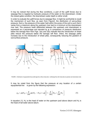
This document discusses the hydraulic design of the main diversion structure of a barrage. It covers sub-surface flow considerations like seepage pressure, exit gradient, and uplift forces. It also discusses surface flow conditions during floods when barrage gates are open. Analytical solutions and graphs are provided to calculate seepage pressures and exit gradient. Corrections are also described to account for factors like floor thickness, slope, and interference between sheet piles. Surface flow hydraulics involve operating barrage gates to pass floods while maintaining the pool water level.

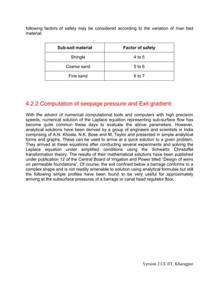
![• A straight horizontal floor of negligible thickness with a sheet pile at either end
[Figure 6(a) or 6(b)].
• A straight horizontal floor of negligible thickness with an intermediate sheet pile
[Figure 6(c)].
• A straight horizontal floor depressed below the bed but with no sheet pile [Figure
6(d)].
The solution for these simple profiles has been obtained in terms of the pressure
head ratio (or percentage) at key points as shown in the figures.
Version 2 CE IIT, Kharagpur](https://image.slidesharecdn.com/m4l02-220208062439/85/M4l02-10-320.jpg)
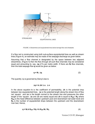
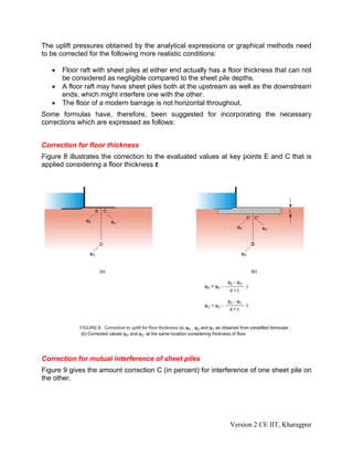
![These key points are the junction points of the sheet pile with floor incase of floors of
negligible thickness and at the corners of the base at the upstream and down stream
end incase of depressed floor. The analytical expressions of each of the above
cases are given as under:
• For sheet piles at either upstream end [Figure 6(a)] or the down stream end
[Figure 6(b)].
φE = (1/π) cos-1
[(λ-2)/ λ] (10)
φD = (1/π) cos-1
[(λ-1)/ λ] (11)
φC 1 = 100 - φE (12)
φD 1 = 100 - φD (13)
φE 1 = 100 (14)
where λ = (1/2)[ 1+√(1+α2
) ]
and α = (b/d)
• For sheet piles at the intermediate point [ Figure 6( c ) ]
φE = (1/π) cos-1
[(λ1-1)/ λ2] (15)
φD = (1/π) cos-1
[λ1/ λ2] (16)
φC = (1/π) cos-1
[(λ1+1)/ λ2] (17)
In the above equations, λ1 and λ2 are given as:
λ1= (1/2)[ √(1+α1
2
) - √(1+α2
2
)] (18)
λ2= (1/2)[ √(1+α1
2
) + √(1+α2
2
)] (19)
where α1 = (b1/d)
α2 = (b2/d)
• For the case of a depressed floor ,
φD' = φD - (2/3)[φE -φD] +(3/ α2
) (20)
φD' = 100 - φD
Version 2 CE IIT, Kharagpur](https://image.slidesharecdn.com/m4l02-220208062439/85/M4l02-11-320.jpg)
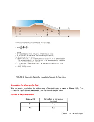
![Where φD and φE are given as
φD = (1/π) cos-1
[(λ-1)/ λ] (21)
φE = (1/π) cos-1
[(λ-2)/ λ] (22)
The above expressions may also be determined from the graph shown in Figure 7.
Version 2 CE IIT, Kharagpur](https://image.slidesharecdn.com/m4l02-220208062439/85/M4l02-12-320.jpg)
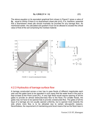
![1:3 4.5
1:4 3.3
1:5 2.8
1:6 2.5
1:7 2.3
1:8 2.0
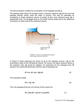
The corrections will have to be taken positive for down slopes and negative for up-
slopes taken in the direction of flow. The corrections are applicable to the key points of
the pile line fixed at the beginning or the end of the slope, for example the pile line 2 at
its end E for the floor and sheet-pile shown in Figure 9.
Corresponding to the downstream sheet pile [Figure 6 (b)], the exit gradient, denoted
as GE, is given below:
Version 2 CE IIT, Kharagpur](https://image.slidesharecdn.com/m4l02-220208062439/85/M4l02-15-320.jpg)
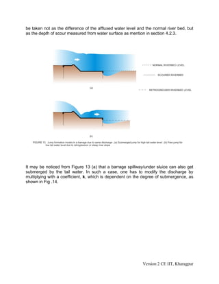
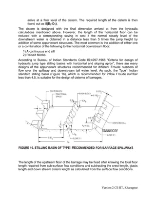
![a river, more and more gate opening is provided till such time when the gates are fully
open.
The corresponding upstream stage-discharge curve shown in Figure 12(a) shows that
up to a river discharge of Q0, the water level behind the barrage is maintained at Pond
Level. At any higher discharge, the stage discharge curve is similar to that of the normal
river downstream [Figure 12(b)] but with an afflux.
Hence, at any discharge Q greater than Q0, the water level behind the barrage (Hu) is
higher than that downstream of the barrage (HD). In some rivers the construction of a
barrage causes the downstream riverbed to get degraded to progressively up to a
certain extent, a phenomenon that is called Retrogression, which has been found to be
more pronounced in alluvial rivers carrying more silt or having finer bed material and
having steep slope. IS 6966 (part 1): 1989 “Hydraulic design of barrages and weirs-
guidelines” recommends a retrogression of 1.25 to 2.25 m for alluvial rivers at lower
river stages depending upon the amount of silt in the river, type of bed material, and
slope. As a result of retrogression, low stages of the river are generally affected more
compared to the maximum flood levels. At the design flood, the reduction of stages due
to retrogression may be within 0.3 to 0.5m depending upon whether the river is shallow
or confined during floods. Figure 12(c) shows a typical retrogressed water stage versus
discharge and for the same discharge Q1, the corresponding water level (HD′ ) would be
much lower than the upstream water level (Hu).
The above discussion implies that for the same flood discharge, a non-retrogressed
river may exhibit submerged flow phenomenon [Figure 13(a)] compared to a free flow
condition [Figure 13(b)] expected for a retrogressed condition. As a consequence, there
Version 2 CE IIT, Kharagpur](https://image.slidesharecdn.com/m4l02-220208062439/85/M4l02-17-320.jpg)
![would be a difference in scour depths in either case. Nevertheless, IS 6966 [part 1]:
1989 recommends that for non cohesive soils, the depth of scour may be calculated
from the Lacey’s formula which is as follows:
R=0.473(Q/f)1/3
when looseness factor is more than 1 (24)
or
R=1.35(q2
/f)1/3
when looseness factor is less than 1 (25)
Where
R=depth of scour below the highest flood level (in meters).
Q=high flood discharge in the river (in m3
/s)
f=silt factor which may be calculated knowing the average particle
size mr(in mm), of the soil from the following relationship
f=1.76√d50
(26)
q=intensity of flood discharge is in m3
/s per meter width
The extent of scour in a river with erodible bed material varies at different places along
a barrage. The likely extent of scour at various points are given in the following table:
Location Range Mean
Upstream cutoff (sheet pile) depth 1.0R*
Downstream cutoff (sheet pile) depth 1.25R*
Flexible apron upstream of impervious floor 1.25 to 1.75R 1.5R
Flexible apron downstream of impervious
floor
1.75 to 2.25R 2.0R
Noses of guide banks 2.00 to 2.50R 2.25R
Noses of divide wall 2.00 to 2.50R 2.25R
Transition from nose to straight 1.25 to 1.75R 1.50R
Straight reaches of guide banks 1.00 to 1.50R 1.25R
* A concentration factor of 20 percent is to be taken into account in fixing the depth of
sheet piles. These should be suitably extended into the banks on both sides up to at
least twice their depth from top of the floors.
Version 2 CE IIT, Kharagpur](https://image.slidesharecdn.com/m4l02-220208062439/85/M4l02-18-320.jpg)
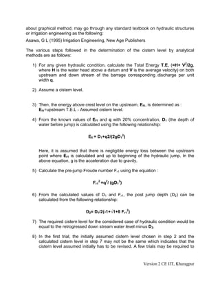
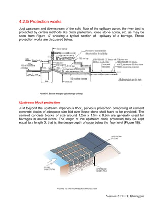
![It is quite common to find layers of clay below the riverbed of alluvial rivers in which
case, a judicious adjustment in the depths of upstream and downstream sheet-piles
shall have to be made to avoid build up of pressure under floor.
4.2.4 Fixing dimensions of barrage components
The hydraulic calculation for a barrage starts with determination of the waterway, as
discussed in Lesson 4.1. For shallow and meandering rivers, the minimum stable width
(P) can be calculated from Lacey’s modified formula
P=4.83 Q1/2
(27)
Where, the discharge Q is in m3
/s. For rivers with very wide sections, the width of the
barrage is limited to Lacey’s width multiplied by looseness factor and the balance width
is blocked by tie bunds with suitable training measures. Assuming the width of each bay
to be between 18m to 20m and pier width to be around 1.5 the total number of bays is
worked out. The total number of bays is distributed between spillway, under-sluice and
river-sluice bays. The crest levels of the different bays may be fixed up on the basis of
the formulations in Lesson 4.1.
With these tentative values, the adequacy of the water way for passing the design flood
within the permissible afflux needs to be checked up. Otherwise, the water way and
crest levels will need to be readjusted in such a way that the permissible values of afflux
are not exceeded.
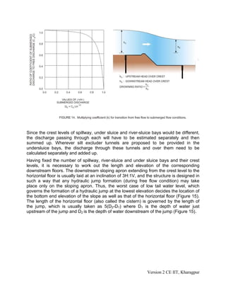
The discharge through the bays of a barrage (spillway or under sluices) for an
uncontrolled condition (as during a flood discharge) is given as:
Q=CLH3/2
(28)
Where L is the clear water way (in meters) H is the total head (including velocity head)
over crest (in meters) and C is the coefficient of discharge, which for free flow conditions
[as shown in Figure 13 (b)] may be taken as 1.705 (for Broad-crested weirs/spillways) or
1.84 (for Sharp-crested weirs/ spillways). Roughly, a spillway or weir is considered to be
Broad Crested if a critical depth occurs over its crest. However, with the general
dimensions of a barrage spillway (with the crest width generally being kept at about 2m)
and the corresponding flow depths usually prevailing, it would mostly act like a Sharp-
Crested spillway. Under sluices and river sluices (without a crest) would behave as
broad-crested weir. Another point that may be kept in mind is that the total head H also
includes the velocity head Va
2
/2g, where Va is the velocity of approach and may be
found by dividing the total discharge by the flow Q cross section area A. The quantity A,
in turn, may be found out by multiplying the river width by the depth of flow, which has to
Version 2 CE IIT, Kharagpur](https://image.slidesharecdn.com/m4l02-220208062439/85/M4l02-19-320.jpg)
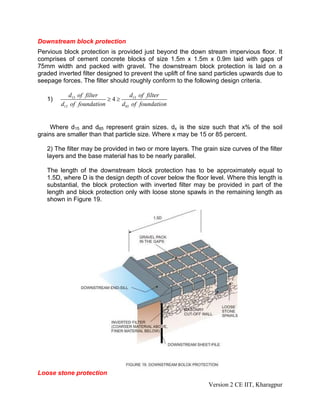
![Beyond the block protection on the upstream and down streams of a barrage located on
alluvial foundation, a layer of loose boulders or stones have to be laid, as shown in
Figure 20(a). The boulder size should be at least 0.3m and should not weigh less than
40kg. This layer of boulders are expected to fall below at an angle , or launch , when
the riverbed down stream starts getting scoured at the commencement of a heavy flood
[Figure 20(b)]. The length of river bed that has to be protected with loose stone blocks
shall be around 1.5D, where D is the depth of scour below average riverbed.
It may be mentioned that the loose stone protection shall have to be laid not only down
stream of the barrage floor, but all along the base of guide bunds, flank walls, abutment
walls, divide walls, under sluice tunnels, as may be observed from the typical layout of a
barrage given in Figure 21.
Version 2 CE IIT, Kharagpur](https://image.slidesharecdn.com/m4l02-220208062439/85/M4l02-27-320.jpg)
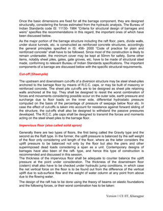
![Beyond the block protection on the upstream and down streams of a barrage located on
alluvial foundation, a layer of loose boulders or stones have to be laid, as shown in
Figure 20(a). The boulder size should be at least 0.3m and should not weigh less than
40kg. This layer of boulders are expected to fall below at an angle , or launch , when
the riverbed down stream starts getting scoured at the commencement of a heavy flood
[Figure 20(b)]. The length of river bed that has to be protected with loose stone blocks
shall be around 1.5D, where D is the depth of scour below average riverbed.
It may be mentioned that the loose stone protection shall have to be laid not only down
stream of the barrage floor, but all along the base of guide bunds, flank walls, abutment
walls, divide walls, under sluice tunnels, as may be observed from the typical layout of a
barrage given in Figure 21.
4.2.6 Structural design of barrage components
Version 2 CE IIT, Kharagpur](https://image.slidesharecdn.com/m4l02-220208062439/85/M4l02-29-320.jpg)


![Geotechnical Engineering-I [Lec #27A: Flow Calculation From Flow Nets]](https://cdn.slidesharecdn.com/ss_thumbnails/27-180924141501-thumbnail.jpg?width=640&height=640&fit=bounds)


