The document details an experimental study of centrifugal pumps conducted by Saif al-Din Ali Madi at the University of Baghdad. It covers the theory behind centrifugal pumps, their classification, and efficiency calculations, including mechanical, hydraulic, volumetric, and overall efficiencies. The objective is to obtain energy, power, and efficiency curves for the pump based on varying flow rates during experiments.
![SAIF AL-DIN ALI MADI
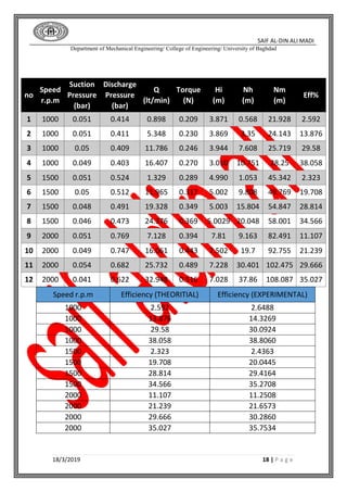
Department of Mechanical Engineering/ College of Engineering/ University of Baghdad
18/3/2019 1 | P a g e
[Fluid Laboratory II]
University of Baghdad
Name: - Saif Al-din Ali -B-](https://image.slidesharecdn.com/centrifugalpump-190507071738/85/Centrifugal-pump-Fluid-Laboratory-1-320.jpg)