The document discusses Lord Pump Company donating a training to Hisham Alkhateeb, the training director at the company. It discusses positive displacement pumps, their objectives in transferring liquids from source to destination or circulating liquids in a system. It then discusses various types of positive displacement pumps like sliding vane pumps, external gear pumps, internal gear pumps, and single screw pumps.


![1] POSITIVE DISPLACEMENT
COMPRESSORS
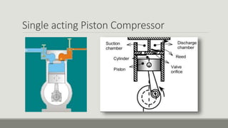
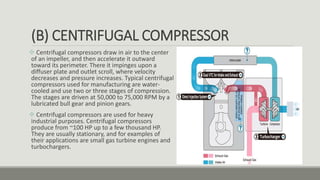
Positive displacement compressors draw in and capture a volume
of air(for example) in a chamber, then reduce the volume of the
chamber to compress the air.
The idea is trapping a certain amount of compressible fluid
pressurize it and then discharge it with the gained energy.
This can be divided into two group Rotary types and Reciprocating
types.](https://image.slidesharecdn.com/pumps-compressors-170812140844/85/Pumps-compressors-53-320.jpg)


![2] DYNAMIC DISPLACEMENT
COMPRESSORS
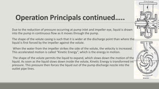
Dynamic Displacement Compressors. Rather than physically reducing the
volume of a captured pocket of air, dynamic compressors instead speed up the
air to high velocity, and then restrict the air flow so that the reduction in velocity
causes pressure to increase. They are oil-free by nature, and some are oil-less.
Dynamic compressors include axial and centrifugal types.](https://image.slidesharecdn.com/pumps-compressors-170812140844/85/Pumps-compressors-61-320.jpg)


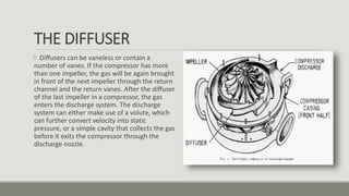
![THE COLLECTOR
The collector of a centrifugal compressor can take many
shapes and forms.[7][18] When the diffuser discharges
into a large empty chamber, the collector may be termed a
Plenum. When the diffuser discharges into a device that
looks somewhat like a snail shell, bull's horn or a French
horn, the collector is likely to be termed a volute or scroll.
As the name implies, a collector’s purpose is to gather the
flow from the diffuser discharge annulus and deliver this
flow to a downstream pipe. Either the collector or the pipe
may also contain valves and instrumentation to control the
compressor.](https://image.slidesharecdn.com/pumps-compressors-170812140844/85/Pumps-compressors-68-320.jpg)


![2938 [autosaved]](https://cdn.slidesharecdn.com/ss_thumbnails/2938autosaved-141224115226-conversion-gate02-thumbnail.jpg?width=640&height=640&fit=bounds)


