This document provides an overview of switching concepts in computer networking, including:
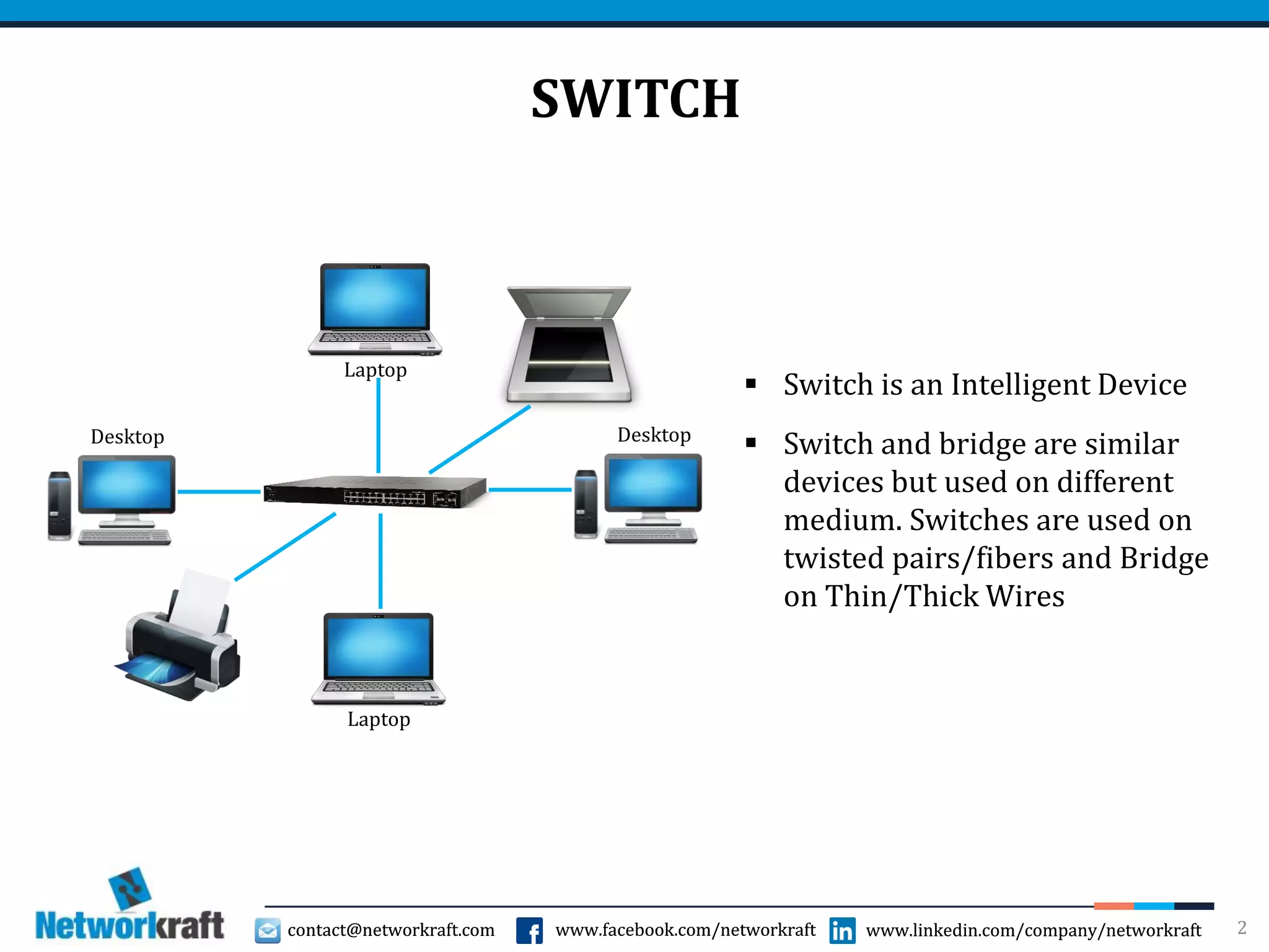
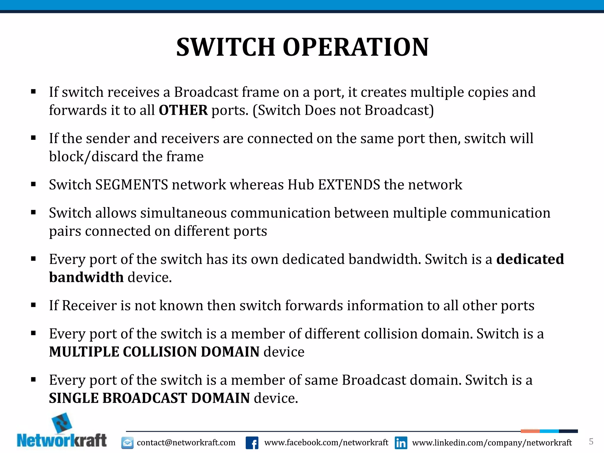
- How switches operate at the data link layer to segment networks and improve performance through dedicated bandwidth on each port.
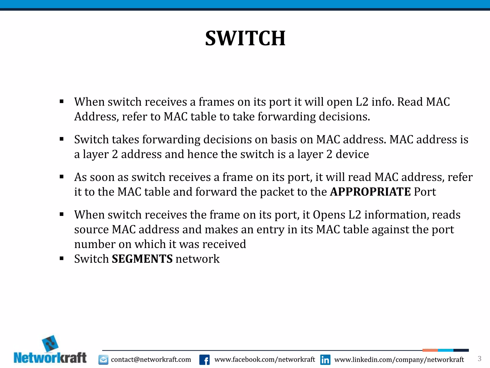
- Key switch functions like reading MAC addresses to populate the MAC address table and make forwarding decisions.
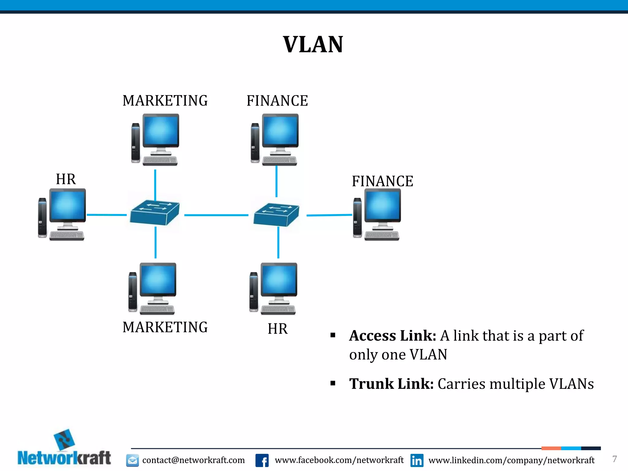
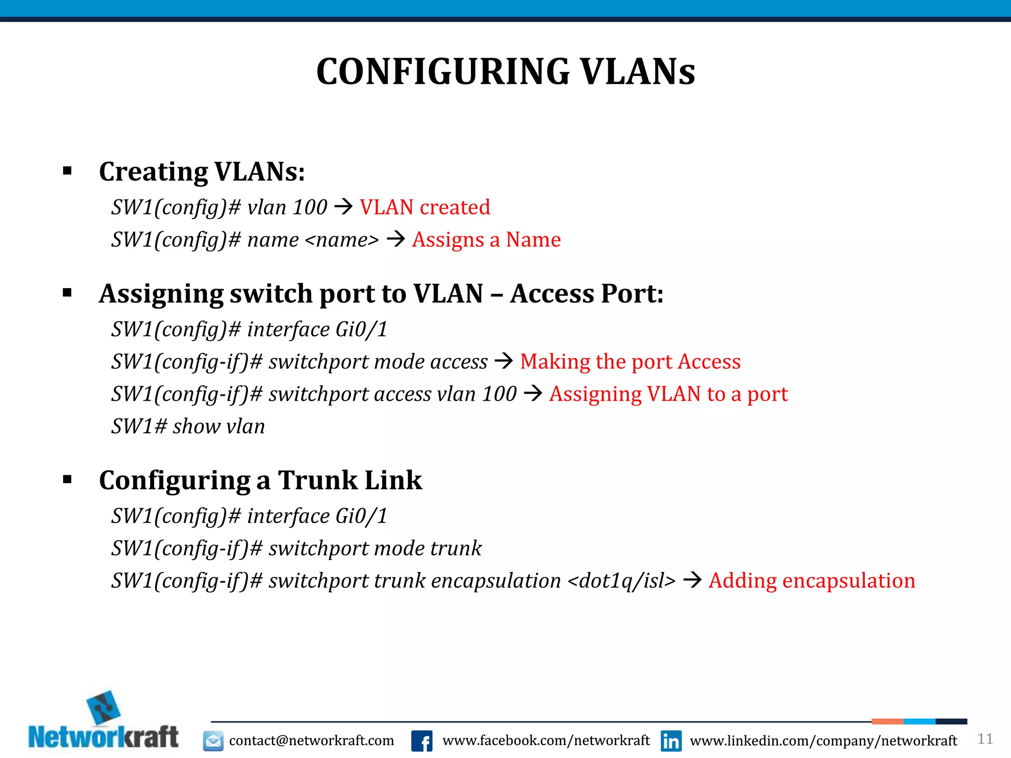
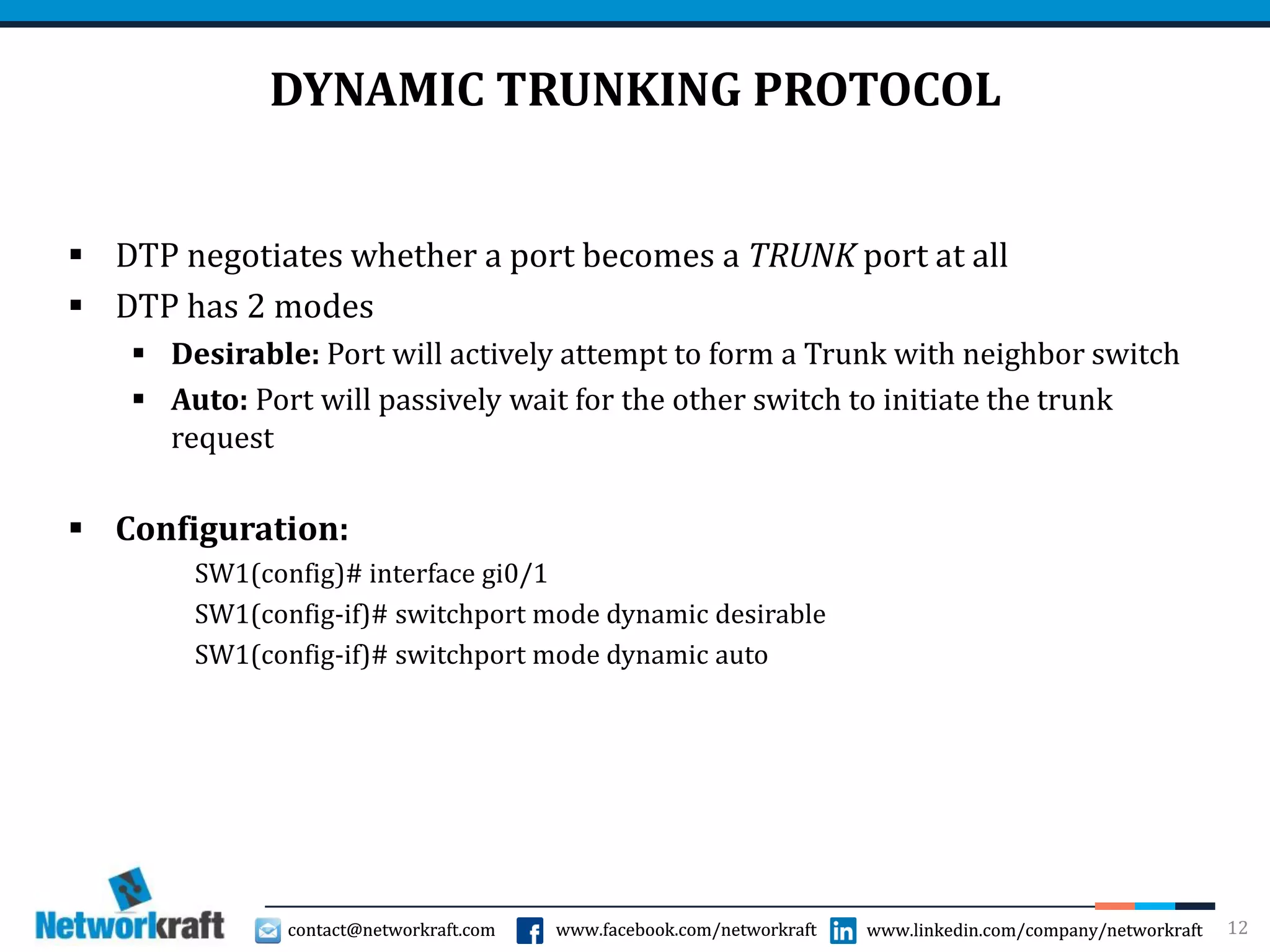
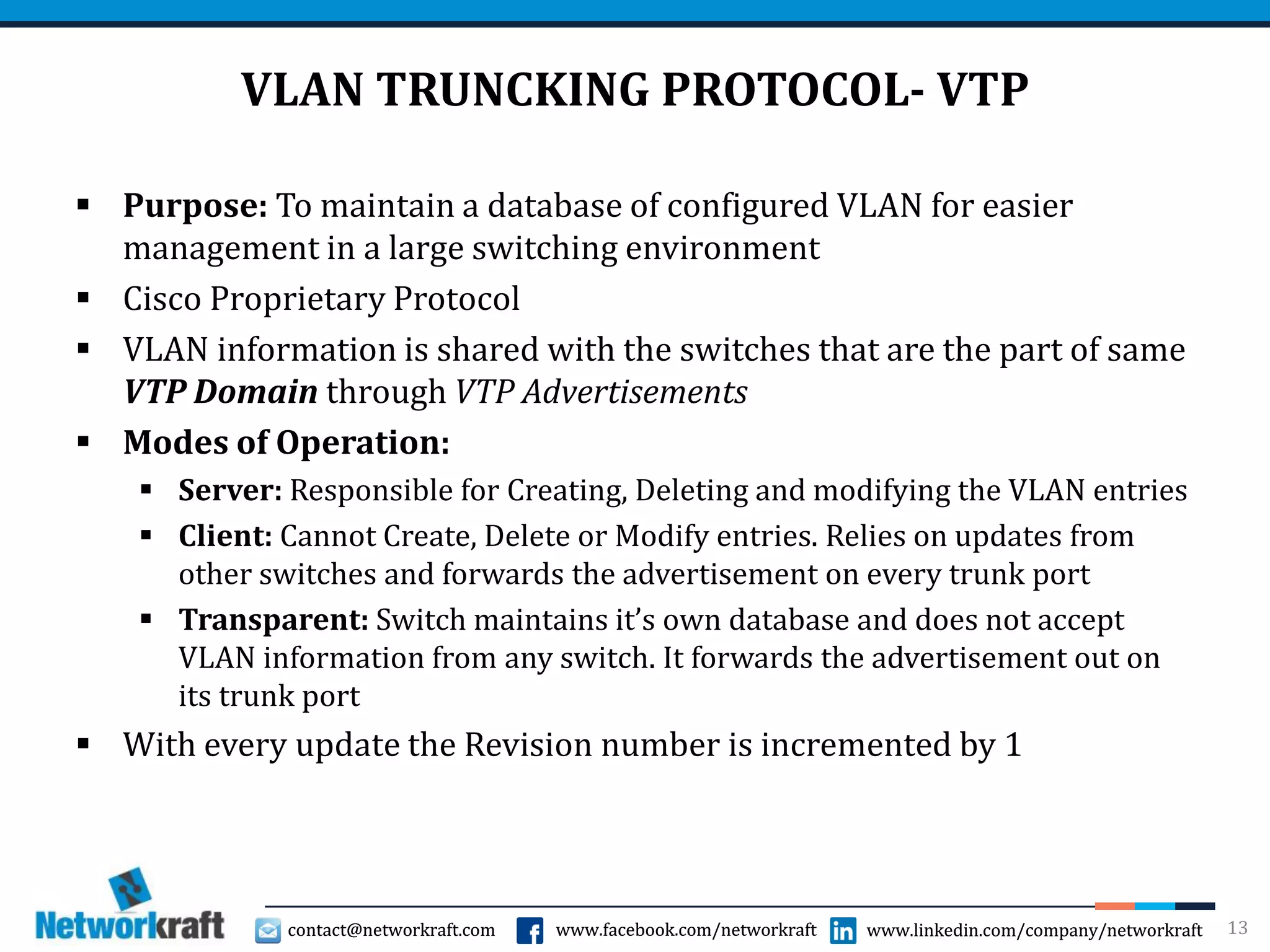
- VLANs and how they logically segment networks for improved management and security.
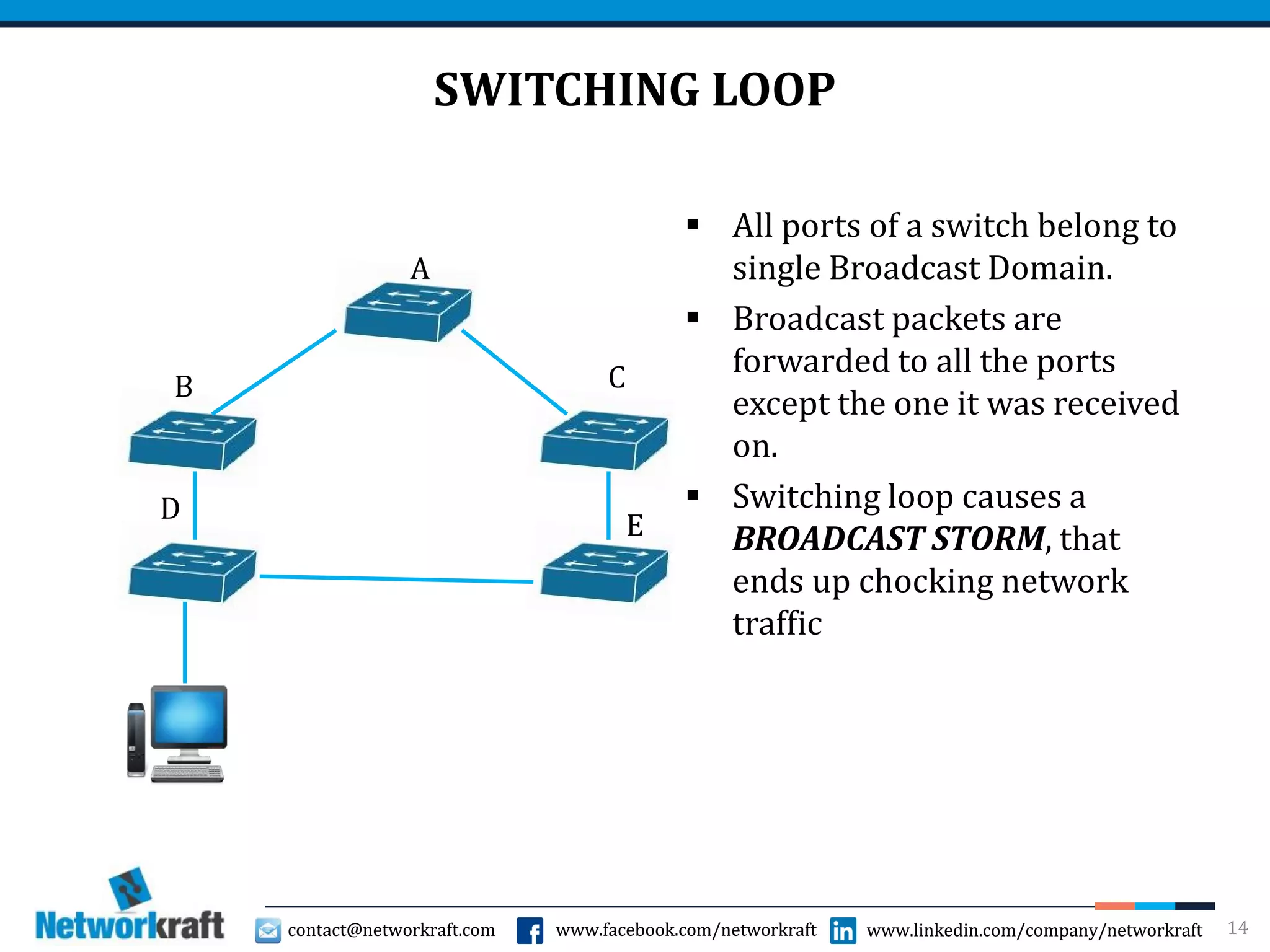
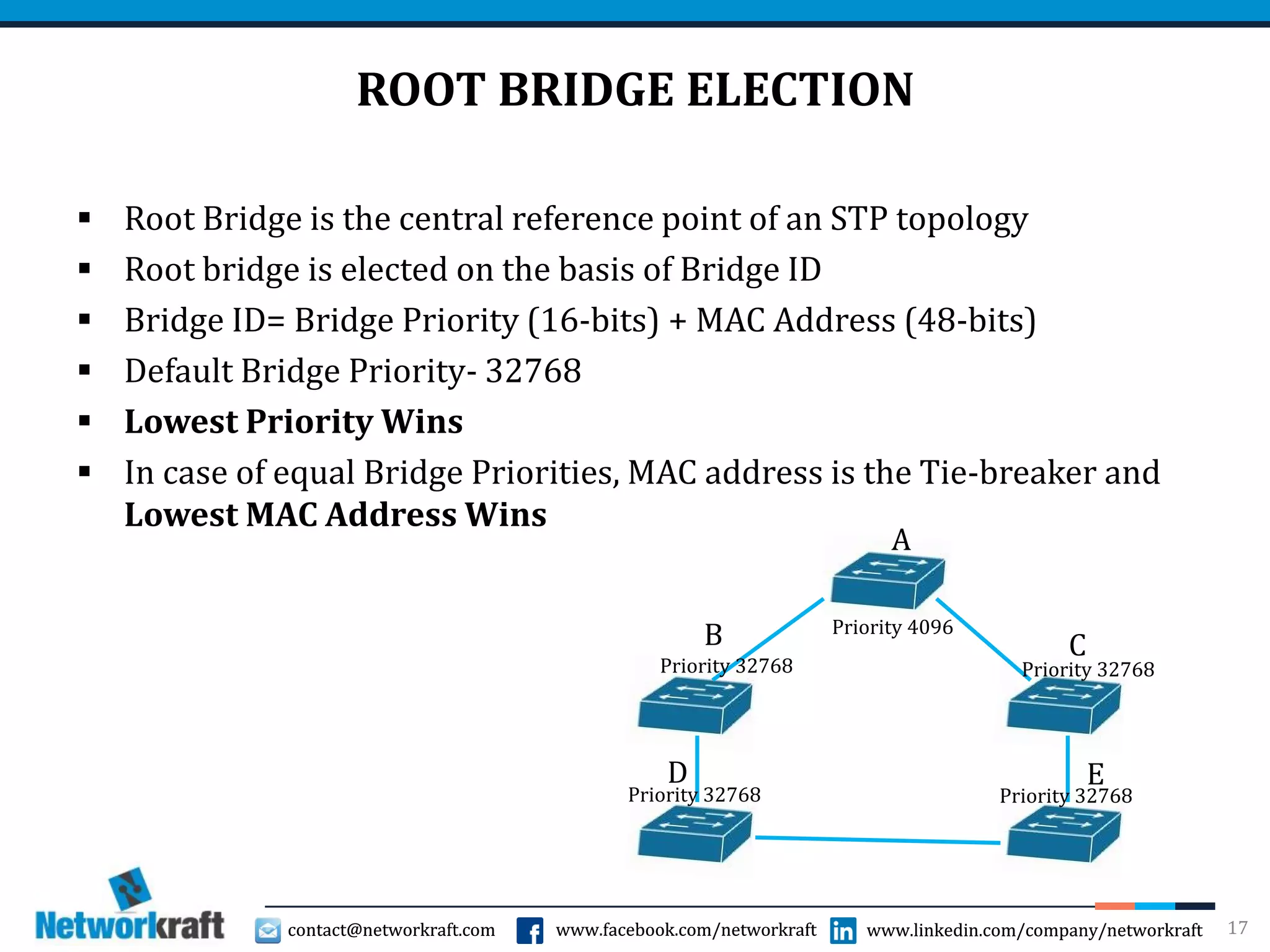
- Spanning Tree Protocol which prevents switching loops by blocking certain ports.
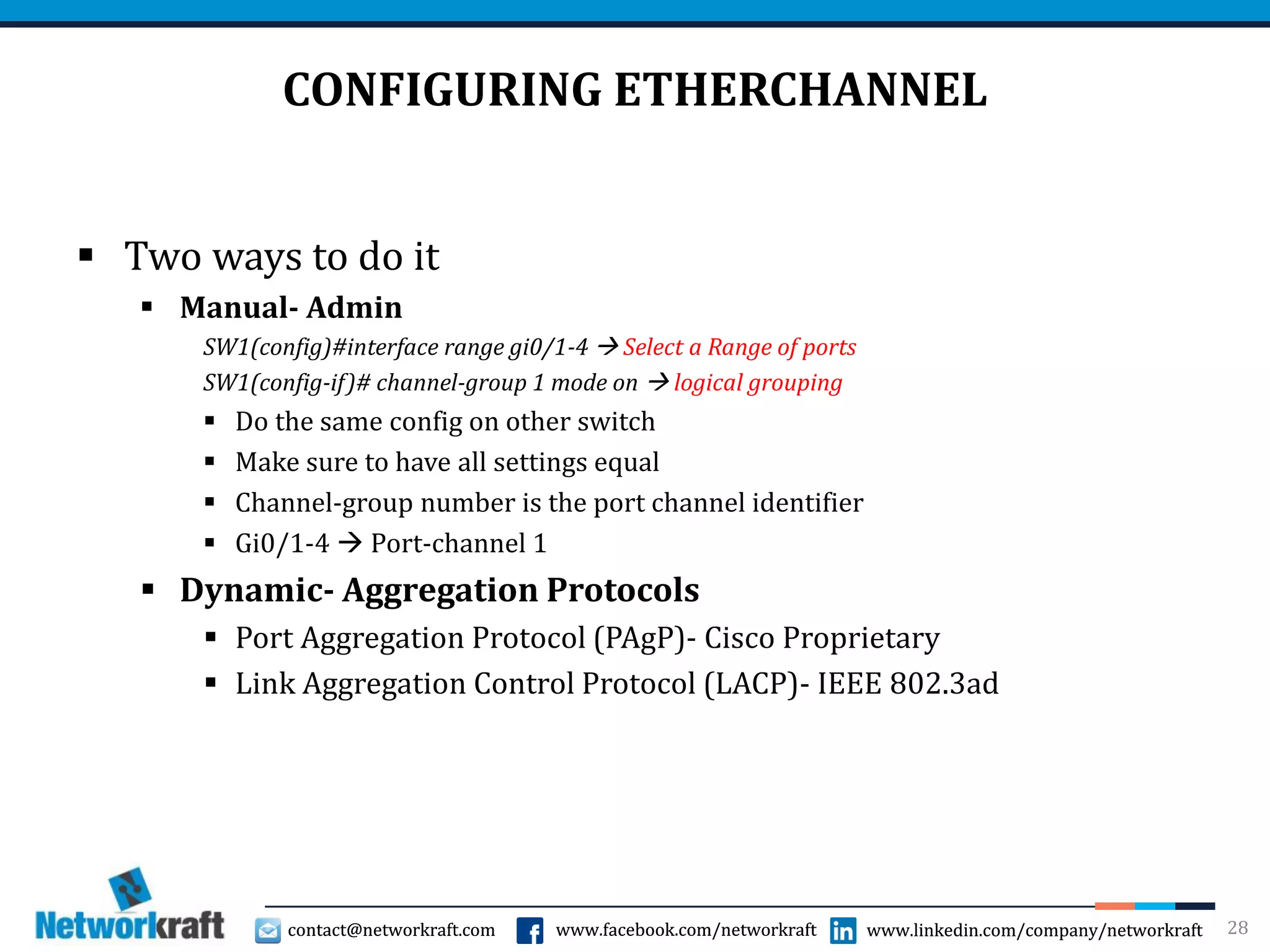
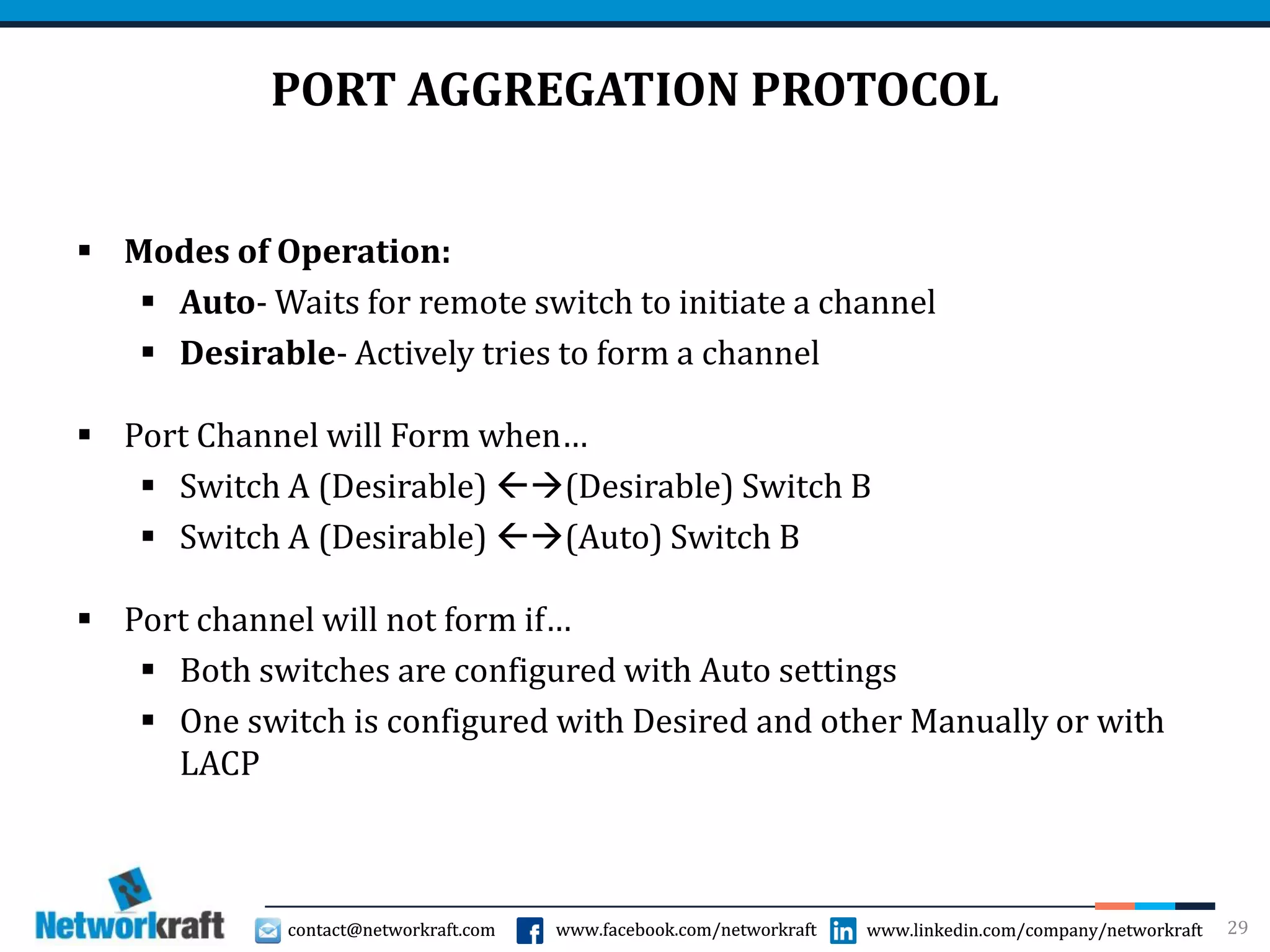
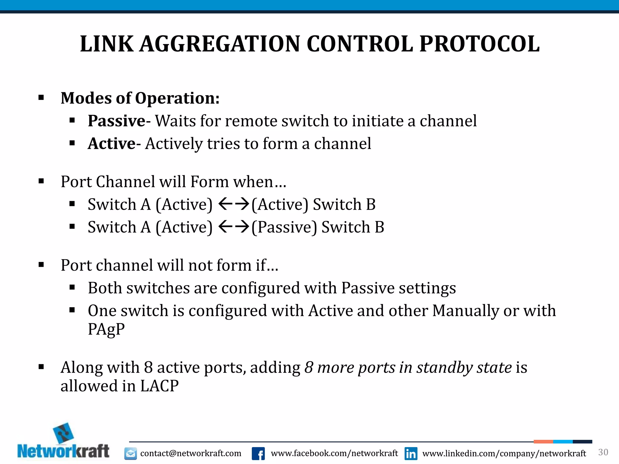
- Port aggregation technologies like EtherChannel that bundle multiple physical ports into a single logical port for redundancy and increased bandwidth.