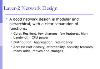
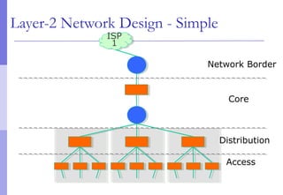
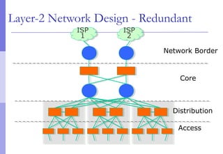
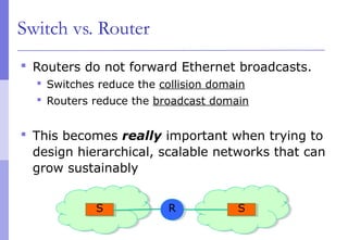
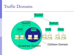
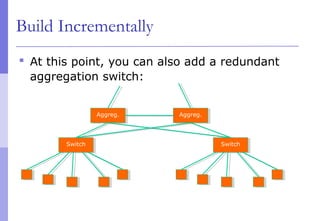
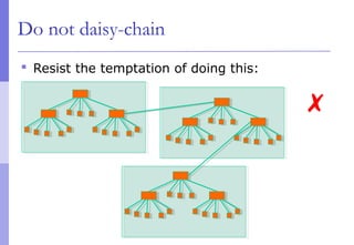
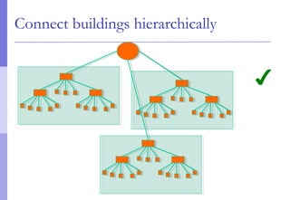
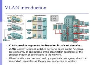
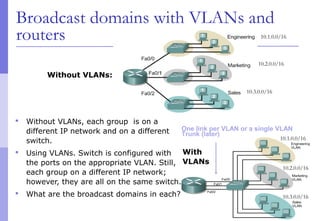
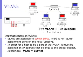
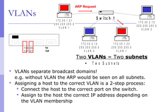
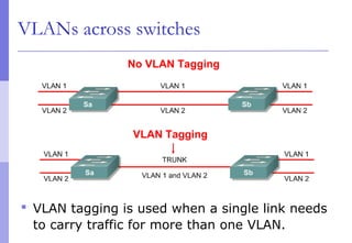
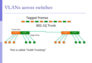
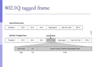
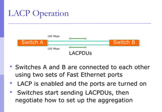
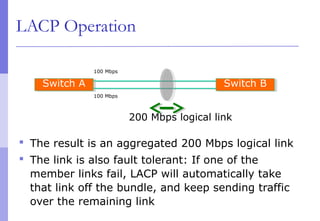
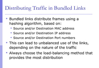
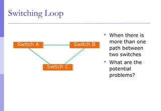
The document discusses layer 2 network design concepts. It describes a hierarchical network design with core, distribution, and access layers. It covers layer 2 protocols like Ethernet and switches, and how switches reduce collision domains compared to hubs. The document also covers VLANs, how they segment broadcast domains, and how VLAN traffic can cross switches using 802.1Q trunking. Finally, it discusses link aggregation using LACP for increased bandwidth or redundancy.
This chapter will cover how to configure, manage, and troubleshoot VLANs and
VLAN trunks. It will also examine security considerations and strategies relating
to VLANs and trunks, and best practices for VLAN design.
Inter-VLAN routing is the process of forwarding network traffic from one VLAN to another VLAN using a
router.
VLANs divide broadcast domains in a LAN environment. Whenever hosts in one VLAN need to
communicate with hosts in another VLAN, the traffic must be routed between them. This is known as
inter-VLAN routing. On Catalyst switches it is accomplished by creating Layer 3 interfaces (Switch virtual
interfaces (SVI)).
1. An introduction of LAN.
2. An introduction of VLAN.
3. Properties of VLAN.
4. Types of VLAN.
5. VLAN Identification Method
6. VLAN Trunking Protocol.
7. Inter-VLAN routing.
Virtual Local Area Network (VLAN) provide a way of grouping different network devices to ensure that those devices can communicate directly with one another.
Présentation de la technologie d'aggrégation de liens sous Cisco.
Fonctionnement, Protocoles PaGP et LACP, Configuration sur les switchs Cisco Catalyst
I tried to make as detailed, clear, abundant example and visual presentation of VLANs as possible. You can contact the e-mail address in the slide to get information about the yours issue or correct my any mistakes.
UiPath Test Automation using UiPath Test Suite series, part 3DianaGray10
Welcome to UiPath Test Automation using UiPath Test Suite series part 3. In this session, we will cover desktop automation along with UI automation.
Topics covered:
UI automation Introduction,
UI automation Sample
Desktop automation flow
Pradeep Chinnala, Senior Consultant Automation Developer @WonderBotz and UiPath MVP
Deepak Rai, Automation Practice Lead, Boundaryless Group and UiPath MVP
Slack (or Teams) Automation for Bonterra Impact Management (fka Social Soluti...Jeffrey Haguewood
Sidekick Solutions uses Bonterra Impact Management (fka Social Solutions Apricot) and automation solutions to integrate data for business workflows.
We believe integration and automation are essential to user experience and the promise of efficient work through technology. Automation is the critical ingredient to realizing that full vision. We develop integration products and services for Bonterra Case Management software to support the deployment of automations for a variety of use cases.
This video focuses on the notifications, alerts, and approval requests using Slack for Bonterra Impact Management. The solutions covered in this webinar can also be deployed for Microsoft Teams.
Interested in deploying notification automations for Bonterra Impact Management? Contact us at sales@sidekicksolutionsllc.com to discuss next steps.
GDG Cloud Southlake #33: Boule & Rebala: Effective AppSec in SDLC using Deplo...James Anderson
Effective Application Security in Software Delivery lifecycle using Deployment Firewall and DBOM
The modern software delivery process (or the CI/CD process) includes many tools, distributed teams, open-source code, and cloud platforms. Constant focus on speed to release software to market, along with the traditional slow and manual security checks has caused gaps in continuous security as an important piece in the software supply chain. Today organizations feel more susceptible to external and internal cyber threats due to the vast attack surface in their applications supply chain and the lack of end-to-end governance and risk management.
The software team must secure its software delivery process to avoid vulnerability and security breaches. This needs to be achieved with existing tool chains and without extensive rework of the delivery processes. This talk will present strategies and techniques for providing visibility into the true risk of the existing vulnerabilities, preventing the introduction of security issues in the software, resolving vulnerabilities in production environments quickly, and capturing the deployment bill of materials (DBOM).
Speakers:
Bob Boule
Robert Boule is a technology enthusiast with PASSION for technology and making things work along with a knack for helping others understand how things work. He comes with around 20 years of solution engineering experience in application security, software continuous delivery, and SaaS platforms. He is known for his dynamic presentations in CI/CD and application security integrated in software delivery lifecycle.
Gopinath Rebala
Gopinath Rebala is the CTO of OpsMx, where he has overall responsibility for the machine learning and data processing architectures for Secure Software Delivery. Gopi also has a strong connection with our customers, leading design and architecture for strategic implementations. Gopi is a frequent speaker and well-known leader in continuous delivery and integrating security into software delivery.
Key Trends Shaping the Future of Infrastructure.pdfCheryl Hung
Keynote at DIGIT West Expo, Glasgow on 29 May 2024.
Cheryl Hung, ochery.com
Sr Director, Infrastructure Ecosystem, Arm.
The key trends across hardware, cloud and open-source; exploring how these areas are likely to mature and develop over the short and long-term, and then considering how organisations can position themselves to adapt and thrive.
State of ICS and IoT Cyber Threat Landscape Report 2024 previewPrayukth K V
The IoT and OT threat landscape report has been prepared by the Threat Research Team at Sectrio using data from Sectrio, cyber threat intelligence farming facilities spread across over 85 cities around the world. In addition, Sectrio also runs AI-based advanced threat and payload engagement facilities that serve as sinks to attract and engage sophisticated threat actors, and newer malware including new variants and latent threats that are at an earlier stage of development.
The latest edition of the OT/ICS and IoT security Threat Landscape Report 2024 also covers:
State of global ICS asset and network exposure
Sectoral targets and attacks as well as the cost of ransom
Global APT activity, AI usage, actor and tactic profiles, and implications
Rise in volumes of AI-powered cyberattacks
Major cyber events in 2024
Malware and malicious payload trends
Cyberattack types and targets
Vulnerability exploit attempts on CVEs
Attacks on counties – USA
Expansion of bot farms – how, where, and why
In-depth analysis of the cyber threat landscape across North America, South America, Europe, APAC, and the Middle East
Why are attacks on smart factories rising?
Cyber risk predictions
Axis of attacks – Europe
Systemic attacks in the Middle East
Download the full report from here:
https://sectrio.com/resources/ot-threat-landscape-reports/sectrio-releases-ot-ics-and-iot-security-threat-landscape-report-2024/
Builder.ai Founder Sachin Dev Duggal's Strategic Approach to Create an Innova...Ramesh Iyer
In today's fast-changing business world, Companies that adapt and embrace new ideas often need help to keep up with the competition. However, fostering a culture of innovation takes much work. It takes vision, leadership and willingness to take risks in the right proportion. Sachin Dev Duggal, co-founder of Builder.ai, has perfected the art of this balance, creating a company culture where creativity and growth are nurtured at each stage.
Generating a custom Ruby SDK for your web service or Rails API using Smithyg2nightmarescribd
Have you ever wanted a Ruby client API to communicate with your web service? Smithy is a protocol-agnostic language for defining services and SDKs. Smithy Ruby is an implementation of Smithy that generates a Ruby SDK using a Smithy model. In this talk, we will explore Smithy and Smithy Ruby to learn how to generate custom feature-rich SDKs that can communicate with any web service, such as a Rails JSON API.
Accelerate your Kubernetes clusters with Varnish CachingThijs Feryn
A presentation about the usage and availability of Varnish on Kubernetes. This talk explores the capabilities of Varnish caching and shows how to use the Varnish Helm chart to deploy it to Kubernetes.
This presentation was delivered at K8SUG Singapore. See https://feryn.eu/presentations/accelerate-your-kubernetes-clusters-with-varnish-caching-k8sug-singapore-28-2024 for more details.
Software Delivery At the Speed of AI: Inflectra Invests In AI-Powered QualityInflectra
In this insightful webinar, Inflectra explores how artificial intelligence (AI) is transforming software development and testing. Discover how AI-powered tools are revolutionizing every stage of the software development lifecycle (SDLC), from design and prototyping to testing, deployment, and monitoring.
Learn about:
• The Future of Testing: How AI is shifting testing towards verification, analysis, and higher-level skills, while reducing repetitive tasks.
• Test Automation: How AI-powered test case generation, optimization, and self-healing tests are making testing more efficient and effective.
• Visual Testing: Explore the emerging capabilities of AI in visual testing and how it's set to revolutionize UI verification.
• Inflectra's AI Solutions: See demonstrations of Inflectra's cutting-edge AI tools like the ChatGPT plugin and Azure Open AI platform, designed to streamline your testing process.
Whether you're a developer, tester, or QA professional, this webinar will give you valuable insights into how AI is shaping the future of software delivery.
JMeter webinar - integration with InfluxDB and GrafanaRTTS
Watch this recorded webinar about real-time monitoring of application performance. See how to integrate Apache JMeter, the open-source leader in performance testing, with InfluxDB, the open-source time-series database, and Grafana, the open-source analytics and visualization application.
In this webinar, we will review the benefits of leveraging InfluxDB and Grafana when executing load tests and demonstrate how these tools are used to visualize performance metrics.
Length: 30 minutes
Session Overview
-------------------------------------------
During this webinar, we will cover the following topics while demonstrating the integrations of JMeter, InfluxDB and Grafana:
- What out-of-the-box solutions are available for real-time monitoring JMeter tests?
- What are the benefits of integrating InfluxDB and Grafana into the load testing stack?
- Which features are provided by Grafana?
- Demonstration of InfluxDB and Grafana using a practice web application
To view the webinar recording, go to:
https://www.rttsweb.com/jmeter-integration-webinar
2. Layer-2 Network Design
A good network design is modular and
hierarchical, with a clear separation of
functions:
Core: Resilient, few changes, few features, high
bandwidth, CPU power
Distribution: Aggregation, redundancy
Access: Port density, affordability, security features,
many adds, moves and changes
5. In-Building and Layer 2
There is usually a correspondence between
building separation and subnet separation
Switching inside a building
Routing between buildings
This will depend on the size of the network
Very small networks can get by with doing
switching between buildings
Very large networks might need to do routing
inside buildings
6. Layer 2 Concepts
Layer 2 protocols basically control access to a
shared medium (copper, fiber, electro-
magnetic waves)
Ethernet is the de-facto wired-standard today
Reasons:
Simple
Cheap
Manufacturers keep making it faster
Wireless (802.11a,b,g,n) is also Layer-2
technology.
7. Ethernet Functions
Source and Destination identification
MAC addresses
Detect and avoid frame collisions
Listen and wait for channel to be available
If collision occurs, wait a random period before
retrying
This is called CASMA-CD: Carrier Sense Multiple Access
with Collision Detection
8. Ethernet Frame
SFD = Start of Frame Delimiter
DA = Destination Address
SA = Source Address
CRC = Cyclick Redundancy Check
9. Evolution of Ethernet Topologies
Bus
Everybody on the same coaxial cable
Star
One central device connects every other node
First with hubs (repeated traffic)
Later with switches (bridged traffic)
Structured cabling for star topologies standardized
10. Switched Star Topology Benefits
It’s modular:
Independent wires for each end node
Independent traffic in each wire
A second layer of switches can be added to build a
hierarchical network that extends the same two
benefits above
ALWAYS DESIGN WITH MODULARITY IN MIND
11. Hub
Receives a frame on one port and sends it out
every other port, always.
Collision domain is not reduced
Traffic ends up in places where it’s not needed
12. Hub
HubHub
A frame sent by one node is always sent to
every other node. Hubs are also called
“repeaters” because they just “repeat” what they
hear.
13. Switch
Learns the location of each node by looking
at the source address of each incoming frame,
and builds a forwarding table
Forwards each incoming frame to the port
where the destination node is
Reduces the collision domain
Makes more efficient use of the wire
Nodes don’t waste time checking frames not destined to
them
15. Switches and Broadcast
A switch broadcasts some frames:
When the destination address is not found in the
table
When the frame is destined to the broadcast
address (FF:FF:FF:FF:FF:FF)
When the frame is destined to a multicast ethernet
address
So, switches do not reduce the broadcast
domain!
16. Switch vs. Router
Routers more or less do with IP packets what
switches do with Ethernet frames
A router looks at the IP packet destination and
checks its routing table to decide where to
forward the packet
Some differences:
IP packets travel inside ethernet frames
IP networks can be logically segmented into
subnets
Switches do not usually know about IP, they only
deal with Ethernet frames
17. Switch vs. Router
Routers do not forward Ethernet broadcasts.
Switches reduce the collision domain
Routers reduce the broadcast domain
This becomes really important when trying to
design hierarchical, scalable networks that can
grow sustainably
SS RR SS
19. Traffic Domains
Try to eliminate collision domains
Get rid of hubs!
Actually hubs are very rare today.
Try to keep your broadcast domain limited to
no more than 250 simultaneously connected
hosts
Segment your network using routers
20. Layer 2 Network Design Guidelines
Always connect hierarchically
If there are multiple switches in a building, use an
aggregation switch
Locate the aggregation switch close to the building
entry point (e.g. fiber panel)
Locate edge switches close to users (e.g. one per
floor)
Max length for Cat 5 is 100 meters
23. Build Incrementally
As you have demand and money, grow like
this:
SwitchSwitch
Aggreg.Aggreg.
Hosts
24. Build Incrementally
And keep growing within the same hierarchy:
Aggreg.Aggreg.
Hosts
SwitchSwitch SwitchSwitch
Hosts
25. Build Incrementally
At this point, you can also add a redundant
aggregation switch:
Aggreg.Aggreg.
Hosts
SwitchSwitch SwitchSwitch
Aggreg.Aggreg.
28. Virtual LANs (VLANs)
Allow us to split switches into separate
(virtual) switches
Only members of a VLAN can see that VLAN’s
traffic
Inter-vlan traffic must go through a router
29. VLAN introduction
VLANs provide segmentation based on broadcast domains.
VLANs logically segment switched networks based on the functions,
project teams, or applications of the organization regardless of the
physical location or connections to the network.
All workstations and servers used by a particular workgroup share the
same VLAN, regardless of the physical connection or location.
30. Local VLANs
2 VLANs or more within a single switch
VLANs address scalability, security, and network
management. Routers in VLAN topologies provide
broadcast filtering, security, and traffic flow management.
Edge ports, where end nodes are connected, are
configured as members of a VLAN
The switch behaves as several virtual switches, sending
traffic only within VLAN members.
Switches may not bridge any traffic between VLANs, as this
would violate the integrity of the VLAN broadcast domain.
Traffic should only be routed between VLANs.
32. Broadcast domains with VLANs and
routers
Without VLANs, each group is on a
different IP network and on a different
switch.
Using VLANs. Switch is configured with
the ports on the appropriate VLAN. Still,
each group on a different IP network;
however, they are all on the same switch.
What are the broadcast domains in each?
Without VLANs:
One link per VLAN or a single VLAN
Trunk (later)
With
VLANs
10.1.0.0/16
10.2.0.0/16
10.3.0.0/16
10.1.0.0/16
10.2.0.0/16
10.3.0.0/16
33. VLANs
T w o V L A N s
T w o S u b n e t s
S w i t c h 11 7 2 . 3 0 . 1 . 2 1
2 5 5 . 2 5 5 . 2 5 5 . 0
V L A N 1
1 7 2 . 3 0 . 2 . 1 0
2 5 5 . 2 5 5 . 2 5 5 . 0
V L A N 2
1 7 2 . 3 0 . 1 . 2 3
2 5 5 . 2 5 5 . 2 5 5 . 0
V L A N 1
1 7 2 . 3 0 . 2 . 1 2
2 5 5 . 2 5 5 . 2 5 5 . 0
V L A N 2
Two VLANs = Two subnets
Important notes on VLANs:
VLANs are assigned to switch ports. There is no “VLAN”
assignment done on the host (usually).
In order for a host to be a part of that VLAN, it must be
assigned an IP address that belongs to the proper subnet.
Remember: VLAN = Subnet
1 2 3 4 5 6 .
1 2 1 2 2 1 .
Port
VLAN
34. VLANs
T w o V L A N s
T w o S u b n e t s
S w i t c h 11 7 2 . 3 0 . 1 . 2 1
2 5 5 . 2 5 5 . 2 5 5 . 0
V L A N 1
1 7 2 . 3 0 . 2 . 1 0
2 5 5 . 2 5 5 . 2 5 5 . 0
V L A N 2
1 7 2 . 3 0 . 1 . 2 3
2 5 5 . 2 5 5 . 2 5 5 . 0
V L A N 1
1 7 2 . 3 0 . 2 . 1 2
2 5 5 . 2 5 5 . 2 5 5 . 0
V L A N 2
Two VLANs = Two subnets
VLANs separate broadcast domains!
e.g. without VLAN the ARP would be seen on all subnets.
Assigning a host to the correct VLAN is a 2-step process:
Connect the host to the correct port on the switch.
Assign to the host the correct IP address depending on
the VLAN membership
1 2 3 4 5 6 .
1 2 1 2 2 1 .
Port
VLAN
ARP Request
35. VLAN operation
As a device enters the network, it
automatically assumes the VLAN membership
of the port to which it is attached.
The default VLAN for every port in the switch
is VLAN 1 and cannot be deleted.
(This statement does not give the whole story. More in the
lab later for interested groups…)
All other ports on the switch may be
reassigned to alternate VLANs.
36. VLANs across switches
Two switches can exchange traffic from one or
more VLANs
Inter-switch links are configured as trunks,
carrying frames from all or a subset of a
switch’s VLANs
Each frame carries a tag that identifies which
VLAN it belongs to
37. VLANs across switches
VLAN tagging is used when a single link needs
to carry traffic for more than one VLAN.
No VLAN Tagging
VLAN Tagging
38. VLANs across switches
802.1Q Trunk
Tagged Frames
VLAN XVLAN X VLAN YVLAN YVLAN XVLAN X VLAN YVLAN Y
Edge Ports
Trunk Port
This is called “VLAN Trunking”
39. 802.1Q
The IEEE standard that defines how ethernet
frames should be tagged when moving across
switch trunks
This means that switches from different
vendors are able to exchange VLAN traffic.
41. Tagged vs. Untagged
Edge ports are not tagged, they are just
“members” of a VLAN
You only need to tag frames in switch-to-
switch links (trunks), when transporting
multiple VLANs
A trunk can transport both tagged and
untagged VLANs
As long as the two switches agree on how to handle
those
42. VLANS increase complexity
You can no longer “just replace” a switch
Now you have VLAN configuration to maintain
Field technicians need more skills
You have to make sure that all the switch-to-
switch trunks are carrying all the necessary
VLANs
Need to keep in mind when adding/removing
VLANs
43. Good reasons to use VLANs
You want to segment your network into
multiple subnets, but can’t buy enough
switches
Hide sensitive infrastructure like IP phones,
building controls, etc.
Separate control traffic from user traffic
Restrict who can access your switch management
address
44. Bad reasons to use VLANs
Because you can, and you feel cool
Because they will completely secure your
hosts (or so you think)
Because they allow you to extend the same IP
network over multiple separate buildings
45. Do not build “VLAN spaghetti”
Extending a VLAN to multiple buildings across
trunk ports
Bad idea because:
Broadcast traffic is carried across all trunks from
one end of the network to another
Broadcast storm can spread across the extent of
the VLAN
Maintenance and troubleshooting nightmare
46. Configuring static VLANs
VLAN 1 is one of the factory-default VLANs.
Configure VLANs:
Switch#conf t
Switch(config)#interface vlan 10
Switch(config-if)#ip address x.x.x.x m.m.m.m
47. Creating VLANs
Create the VLAN:
Switch#vlan database
Switch(vlan)#vlan vlan_number
Switch(vlan)#exit
Assign ports to the VLAN (in configuration mode):
Switch(config)#interface fastethernet 0/9
Switch(config-if)#switchport access vlan 10
access – Denotes this port as an access port and not a trunk
vlan
10
Default
vlan 1
Default
vlan 1
48. Verifying VLANs – show vlan-switch
vlan 3vlan 2vlan 1
default
show vlan-switch
50. vlan database commands
Optional Command to add, delete, or modify VLANs.
VLAN names, numbers, and VTP (VLAN Trunking Protocol)
information can be entered which “may” affect other switches
besides this one. (Not part of this module)
This does not assign any VLANs to an interface.
Switch#vlan database
Switch(vlan)#?
VLAN database editing buffer manipulation commands:
abort Exit mode without applying the changes
apply Apply current changes and bump revision number
exit Apply changes, bump revision number, and exit mode
no Negate a command or set its defaults
reset Abandon current changes and reread current database
show Show database information
vlan Add, delete, or modify values associated with a single VLAN
vtp Perform VTP administrative functions.
51. VLAN trunking
To configure 802.1q trunking switch/router, first
determine which ports on the switches will be
used to connect the two switches together.
Then in the Global configuration mode
enter the following commands on both switches:
Switch_A(config)#interface fastethernet
interface ifnumber
Switch_A(config-if)#switchport trunk
encapsulation dot1q
52. Deleting a Port VLAN Membership
Switch(config-if)#no switchport access vlan vlan_number
Deleting a VLAN
Switch#vlan database
Switch(vlan)#no vlan vlan_number
Switch(vlan)#exit
54. Link Aggregation
Also known as port bundling, link bundling
You can use multiple links in parallel as a
single, logical link
For increased capacity
For redundancy (fault tolerance)
LACP (Link Aggregation Control Protocol) is a
standardized method of negotiating these
bundled links between switches
55. LACP Operation
Two switches connected via multiple links will
send LACPDU packets, identifying themselves
and the port capabilities
They will then automatically build the logical
aggregated links, and then pass traffic.
Switch ports can be configured as active or
passive
56. LACP Operation
Switches A and B are connected to each other
using two sets of Fast Ethernet ports
LACP is enabled and the ports are turned on
Switches start sending LACPDUs, then
negotiate how to set up the aggregation
Switch ASwitch A Switch BSwitch B
LACPDUs
100 Mbps
100 Mbps
57. LACP Operation
The result is an aggregated 200 Mbps logical link
The link is also fault tolerant: If one of the
member links fail, LACP will automatically take
that link off the bundle, and keep sending traffic
over the remaining link
200 Mbps logical link
Switch ASwitch A Switch BSwitch B
100 Mbps
100 Mbps
58. Distributing Traffic in Bundled Links
Bundled links distribute frames using a
hashing algorithm, based on:
Source and/or Destination MAC address
Source and/or Destination IP address
Source and/or Destination Port numbers
This can lead to unbalanced use of the links,
depending on the nature of the traffic
Always choose the load-balancing method that
provides the most distribution
60. Switching Loop
When there is
more than one
path between
two switches
What are the
potential
problems?
Switch ASwitch A Switch BSwitch B
Swtich CSwtich C
61. Switching Loop
If there is more than one path between two
switches:
Forwarding tables become unstable
Source MAC addresses are repeatedly seen coming from
different ports
Switches will broadcast each other’s broadcasts
All available bandwidth is utilized
Switch processors cannot handle the load
62. Switching Loop
Switch ASwitch A Switch BSwitch B
Swtich CSwtich C
Node1 sends a
broadcast frame
(e.g. an ARP request)
Node 1
63. Switching Loop
Switch ASwitch A Switch BSwitch B
Swtich CSwtich C
Switches A, B and
C broadcast node
1’s frame out
every port
Node 1
64. Switching Loop
Switch ASwitch A Switch BSwitch B
Swtich CSwtich C
But they receive
each other’s
broadcasts, which
they need to
forward again out
every port!
The broadcasts are
amplified, creating
a broadcast
storm…
Node 1
65. Good Switching Loops???
But you can take advantage of loops!
Redundant paths improve resilience when:
A switch fails
Wiring breaks
How to achieve redundancy without creating
dangerous traffic loops?
66. What is a Spanning Tree
“Given a connected,
undirected graph, a
spanning tree of that
graph is a subgraph
which is a tree and
connects all the vertices
together”.
A single graph can have
many different spanning
trees.
67. Spanning Tree Protocol
The purpose of the protocol is to have bridges
dynamically discover a subset of the topology
that is loop-free (a tree) and yet has just
enough connectivity so that where physically
possible, there is a path between every switch
68. Spanning Tree Protocol
Several flavors:
Traditional Spanning Tree (802.1d)
Rapid Spanning Tree or RSTP (802.1w)
Multiple Spanning Tree or MSTP (802.1s)
69. Traditional Spanning Tree (802.1d)
Switches exchange messages that allow them
to compute the Spanning Tree
These messages are called BPDUs (Bridge Protocol
Data Units)
Two types of BPDUs:
Configuration
Topology Change Notification (TCN)
70. Traditional Spanning Tree (802.1d)
First Step:
Decide on a point of reference: the Root Bridge
The election process is based on the Bridge ID,
which is composed of:
The Bridge Priority: A two-byte value that is configurable
The MAC address: A unique, hardcoded address that
cannot be changed.
71. Root Bridge Selection (802.1d)
Each switch starts by sending out BPDUs with
a Root Bridge ID equal to its own Bridge ID
I am the root!
Received BPDUs are analyzed to see if a lower
Root Bridge ID is being announced
If so, each switch replaces the value of the
advertised Root Bridge ID with this new lower ID
Eventually, they all agree on who the Root
Bridge is
72. Root Bridge Selection (802.1d)
All switches have the same priority.
Who is the elected root bridge?
Switch BSwitch B Switch CSwitch C
Switch ASwitch A
32678.0000000000AA
32678.0000000000BB 32678.0000000000CC
73. Root Port Selection (802.1d)
Now each switch needs to figure out where it
is in relation to the Root Bridge
Each switch needs to determine its Root Port
The key is to find the port with the lowest Root
Path Cost
The cumulative cost of all the links leading to the Root
Bridge
74. Root Port Selection (802.1d)
Each link on a switch has a Path Cost
Inversely proportional to the link speed
e.g. the faster the link, the lower the cost
Link Speed STP Cost
10 Mbps 100
100 Mbps 19
1 Gbps 4
10 Gbps 2
75. Root Port Selection (802.1d)
Root Path Cost is the accumulation of a link’s
Path Cost and the Path Costs learned from
neighboring Switches.
It answers the question: How much does it cost to
reach the Root Bridge through this port?
76. Root Port Selection (802.1d)
1. Root Bridge sends out BPDUs with a Root
Path Cost value of 0
2. Neighbor receives BPDU and adds port’s Path
Cost to Root Path Cost received
3. Neighbor sends out BPDUs with new
cumulative value as Root Path Cost
4. Other neighbor’s down the line keep adding
in the same fashion
77. Root Port Selection (802.1d)
On each switch, the port where the lowest
Root Path Cost was received becomes the
Root Port
This is the port with the best path to the Root
Bridge
78. 32678.0000000000BB 32678.0000000000CC
Root Port Selection (802.1d)
Cost=19 Cost=19
Cost=19
What is the Path Cost on each Port?
What is the Root Port on each switch?
Switch BSwitch B Switch CSwitch C
Switch ASwitch A
32678.0000000000AA
1 2
1 1
2 2
79. 32678.0000000000BB 32678.0000000000CC
Root Port Selection (802.1d)
Cost=19 Cost=19
Cost=19Switch BSwitch B Switch CSwitch C
Switch ASwitch A
32678.0000000000AA
1 2
1 1
2 2
Root
Port
Root
Port
Root
Port
Root
Port
80. Electing Designated Ports (802.1d)
OK, we now have selected root ports but we
haven’t solved the loop problem yet, have we?
The links are still active!
Each network segment needs to have only one
switch forwarding traffic to and from that
segment
Switches then need to identify one
Designated Port per link
The one with the lowest cumulative Root Path Cost
to the Root Bridge
81. 32678.0000000000BB 32678.0000000000CC
Root Port Selection (802.1d)
Cost=19 Cost=19
Cost=19Switch BSwitch B Switch CSwitch C
Switch ASwitch A
32678.0000000000AA
1 2
1 1
2 2
Which port should be the Designated Port on
each segment?
82. Electing Designated Ports (802.1d)
Two or more ports in a segment having
identical Root Path Costs is possible, which
results in a tie condition
All STP decisions are based on the following
sequence of conditions:
Lowest Root Bridge ID
Lowest Root Path Cost to Root Bridge
Lowest Sender Bridge ID
Lowest Sender Port ID
83. 32678.0000000000BB 32678.0000000000CC
Root Port Selection (802.1d)
Cost=19 Cost=19
Cost=19Switch BSwitch B Switch CSwitch C
Switch ASwitch A
32678.0000000000AA
1 2
1 1
2 2
Designate
d Port
Designate
d Port
Designate
d Port
Designate
d Port
Designate
d Port
Designate
d Port In the B-C link, Switch B
has the lowest Bridge ID,
so port 2 in Switch B is
the Designated Port
84. Blocking a port
Any port that is not elected as either a Root
Port, nor a Designated Port is put into the
Blocking State.
This step effectively breaks the loop and
completes the Spanning Tree.
85. 32678.0000000000BB 32678.0000000000CC
Root Port Selection (802.1d)
Cost=19 Cost=19
Cost=19Switch BSwitch B Switch CSwitch C
Switch ASwitch A
32678.0000000000AA
1 2
1 1
2 2
Port 2 in Switch C is put into the Blocking
State, because it is neither a Root Port nor
a Designated Port
✗
86. Spanning Tree Protocol States
Disabled
Port is shut down
Blocking
Not forwarding frames
Receiving BPDUs
Listening
Not forwarding frames
Sending and receiving BPDUs
87. Spanning Tree Protocol States
Learning
Not forwarding frames
Sending and receiving BPDUs
Learning new MAC addresses
Forwarding
Forwarding frames
Sending and receiving BPDUs
Learning new MAC addresses
88. STP Topology Changes
Switches will recalculate if:
A new switch is introduced
It could be the new Root Bridge!
A switch fails
A link fails
89. Root Bridge Placement
Using default STP parameters might result in
an undesired situation
Traffic will flow in non-optimal ways
An unstable or slow switch might become the root
You need to plan your assignment of bridge
priorities carefully
90. Bad Root Bridge Placement
Switch BSwitch B
Switch CSwitch C
Swtich DSwtich D32678.0000000000DD 32678.0000000000BB
32678.0000000000CC
Switch ASwitch A 32678.0000000000AA
Root
Bridge
Root
Bridge
Out to router
91. Good Root Bridge Placement
Switch BSwitch B
Switch CSwitch C
Swtich DSwtich D1.0000000000DD 0.0000000000BB
32678.0000000000CC
Switch ASwitch A 32678.0000000000AA
Alternative
Root Bridge
Alternative
Root Bridge
Out to active
router
Root
Bridge
Root
Bridge
Out to standby
router
92. Protecting the STP Topology
Some vendors have included features that
protect the STP topology:
Root Guard
BPDU Guard
Loop Guard
UDLD
Etc.
93. STP Design Guidelines
Enable spanning tree even if you don’t have
redundant paths
Always plan and set bridge priorities
Make the root choice deterministic
Include an alternative root bridge
If possible, do not accept BPDUs on end user
ports
94. 802.1d Convergence Speeds
Moving from the Blocking state to the Forwarding
State takes at least 2 x Forward Delay time units
(~ 30 secs.)
This can be annoying when connecting end user stations
Some vendors have added enhancements such as
PortFast, which will reduce this time to a minimum for
edge ports
Never use PortFast or similar in switch-to-switch links
Topology changes typically take 30 seconds
too
This can be unacceptable in a production network
95. Rapid Spanning Tree (802.1w)
Convergence is much faster
Communication between switches is more
interactive
Edge ports don’t participate
Edge ports transition to forwarding state
immediately
If BPDUs are received on an edge port, it becomes
a non-edge port to prevent loops
96. Rapid Spanning Tree (802.1w)
Defines these port roles:
Root Port (same as with 802.1d)
Alternate Port
A port with an alternate path to the root
Designated Port (same as with 802.1d)
Backup Port
A backup/redundant path to a segment where another
bridge port already connects.
97. Rapid Spanning Tree (802.1w)
Synchronization process uses a handshake
method
After a root is elected, the topology is built in
cascade, where each switch proposes to be the
designated bridge for each point-to-point link
While this happens, all the downstream switch links
are blocking
98. Rapid Spanning Tree (802.1w)
RootRoot
SwitchSwitch
Proposal
SwitchSwitch
Agreement
SwitchSwitch
SwitchSwitch
DP
RP
99. Rapid Spanning Tree (802.1w)
RootRoot
SwitchSwitch
Proposal
SwitchSwitch
Agreement
SwitchSwitch
SwitchSwitch
DP
RP
DP
RP
100. Rapid Spanning Tree (802.1w)
RootRoot
SwitchSwitch
Proposal
SwitchSwitch
Agreement
SwitchSwitch
SwitchSwitch
DP
RP
DP
RP
DP
RP
101. Rapid Spanning Tree (802.1w)
RootRoot
SwitchSwitch
Proposal
SwitchSwitch
Agreement
SwitchSwitch
SwitchSwitch
DP
RP
DP
RP
DP
RP
DP
RP
102. Rapid Spanning Tree (802.1w)
Prefer RSTP over STP if you want faster
convergence
Always define which ports are edge ports
103. Multiple Spanning Tree (802.1s)
Allows separate spanning trees per VLAN
group
Different topologies allow for load balancing
between links
Each group of VLANs are assigned to an “instance”
of MST
Compatible with STP and RSTP
105. Multiple Spanning Tree (802.1s)
MST Region
Switches are members of a region if they have the
same set of attributes:
MST configuration name
MST configuration revision
Instance-to-VLAN mapping
A digest of these attributes is sent inside the
BPDUs for fast comparison by the switches
One region is usually sufficient
106. Multiple Spanning Tree (802.1s)
CST = Common Spanning Tree
In order to interoperate with other versions of
Spanning Tree, MST needs a common tree that
contains all the other islands, including other MST
regions
IST = Internal Spanning Tree
Internal to the Region, that is
Presents the entire region as a single virtual bridge
to the CST outside
107. Multiple Spanning Tree (802.1s)
MST Instances
Groups of VLANs are mapped to particular
Spanning Tree instances
These instances will represent the alternative
topologies, or forwarding paths
You specify a root and alternate root for each
instance
109. Multiple Spanning Tree (802.1s)
Design Guidelines
Determine relevant forwarding paths, and
distribute your VLANs equally into instances
matching these topologies
Assign different root and alternate root switches to
each instance
Make sure all switches match region attributes
Do not assign VLANs to instance 0, as this is used
by the IST
110. Selecting Switches
Minimum features:
Standards compliance
Encrypted management (SSH/HTTPS)
VLAN trunking
Spanning Tree (RSTP at least)
SNMP
At least v2 (v3 has better security)
Traps
111. Selecting Switches
Other recommended features:
DHCP Snooping
Prevent end-users from running a rogue DHCP server
Happens a lot with little wireless routers (Netgear, Linksys,
etc) plugged in backwards
Uplink ports towards the legitimate DHCP server are
defined as “trusted”. If DHCPOFFERs are seen coming
from any untrusted port, they are dropped.
112. Selecting Switches
Other recommended features:
Dynamic ARP inspection
A malicious host can perform a man-in-the-middle attack
by sending gratuitous ARP responses, or responding to
requests with bogus information
Switches can look inside ARP packets and discard
gratuitous and invalid ARP packets.
113. Selecting Switches
Other recommended features:
IGMP Snooping:
Switches normally flood multicast frames out every port
Snooping on IGMP traffic, the switch can learn which
stations are members of a multicast group, thus
forwarding multicast frames only out necessary ports
Very important when users run Norton Ghost, for example.
114. Network Management
Enable SNMP traps and/or syslog
Collect and process in centralized log server
Spanning Tree Changes
Duplex mismatches
Wiring problems
Monitor configurations
Use RANCID to report any changes in the switch
configuration
115. Network Management
Collect forwarding tables with SNMP
Allows you to find a MAC address in your network
quickly
You can use simple text files + grep, or a web tool
with DB backend
Enable LLDP (or CDP or similar)
Shows how switches are connected to each other
and to other network devices
116. Documentation
Document where your switches are located
Name switch after building name
E.g. building1-sw1
Keep files with physical location
Floor, closet number, etc.
Document your edge port connections
Room number, jack number, server name