Downloaded 412 times
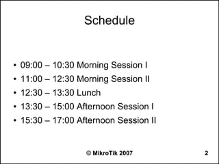

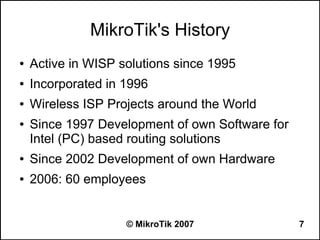


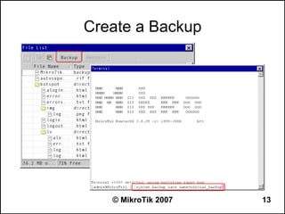
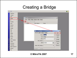
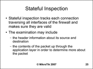


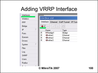

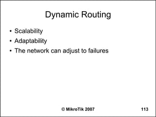


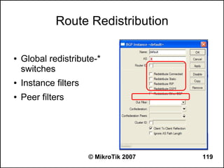


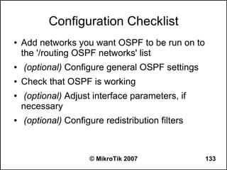
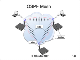
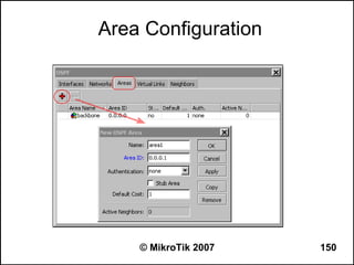
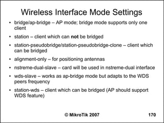
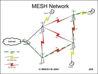
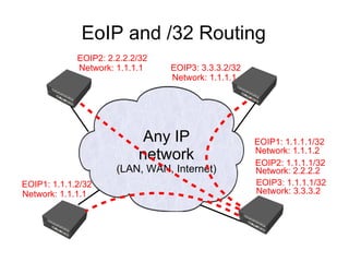
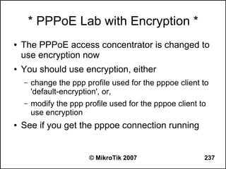
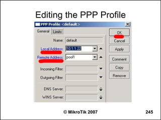
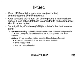
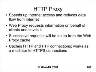
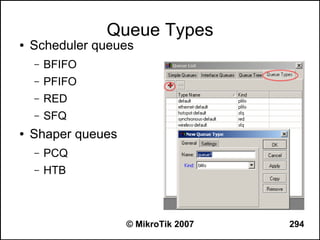
![OSPF Route Redistribution
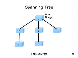
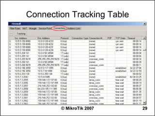
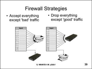
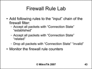
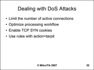
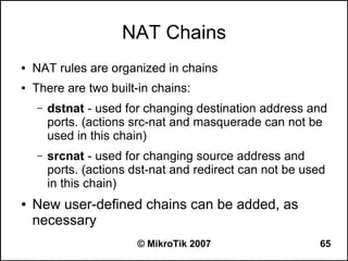
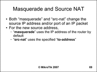
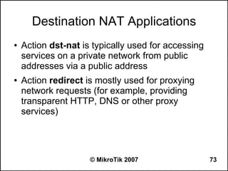
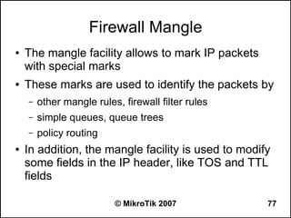
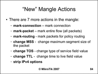
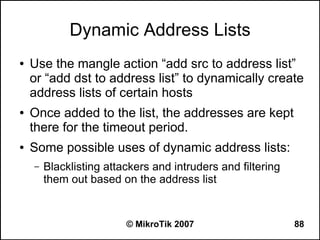
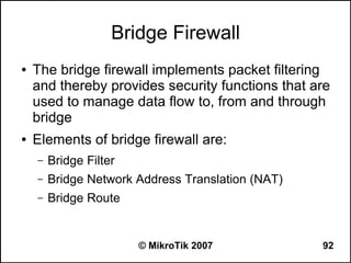
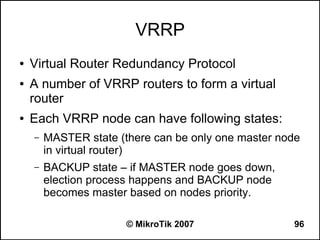
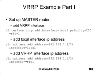
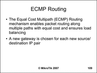
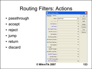
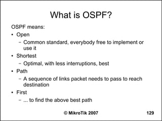
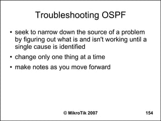
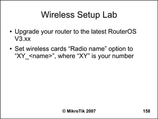
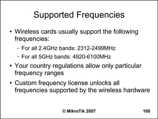
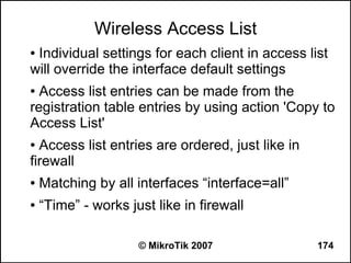
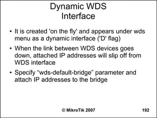
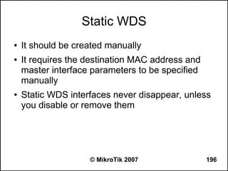
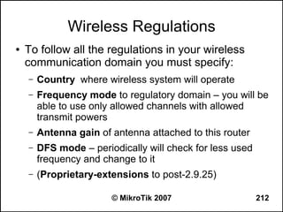
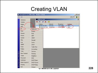
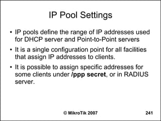
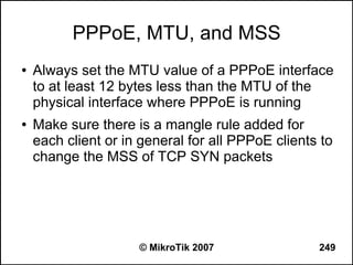
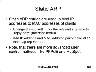
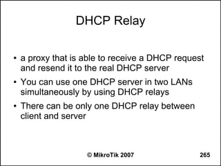
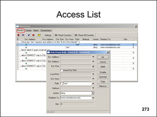
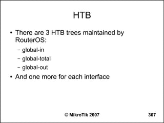
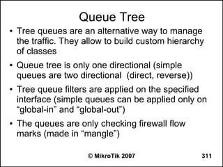
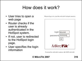
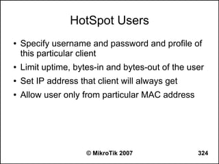
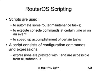
● Set redistribute connected routes [and static
routes]:
/routing ospf
set redistribute-connected=as-type-1
set redistribute-static=as-type-1
● If you use RIP or BGP as well, you may want
to redistribute routes learned by these
protocols
© MikroTik 2007 141](https://image.slidesharecdn.com/mikrotikadvancedtraining-130131071147-phpapp01/85/Mikro-tik-advanced-training-141-320.jpg)
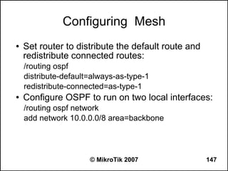
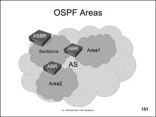
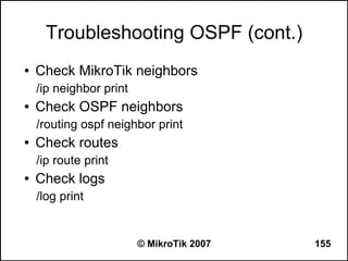
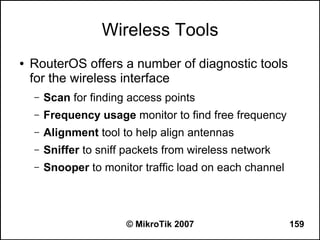
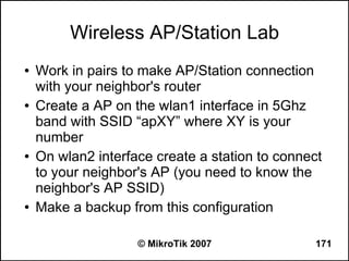


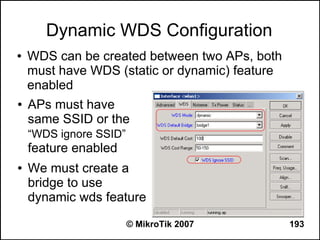
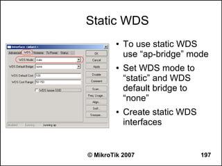
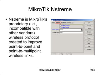
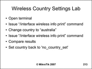
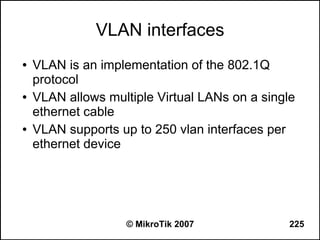
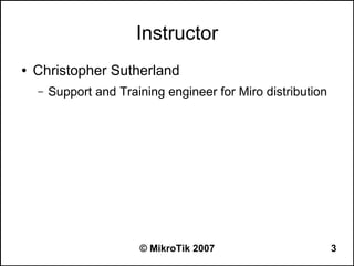
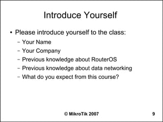
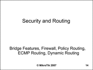
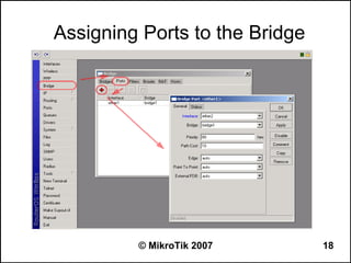
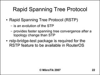
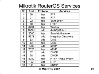
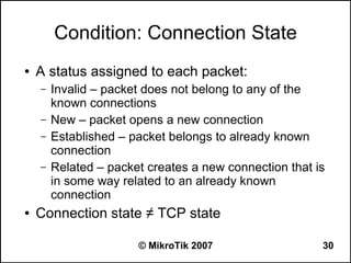
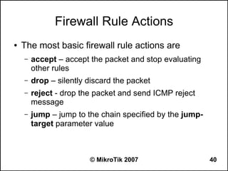
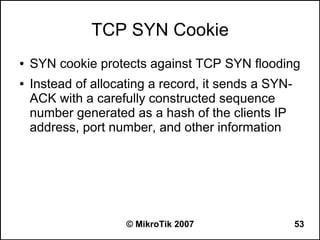
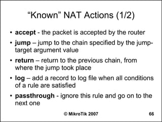
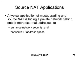
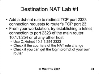
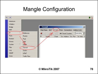
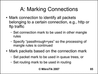
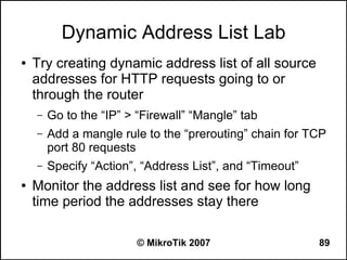
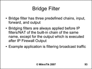
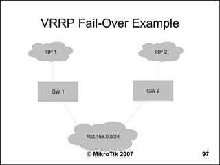
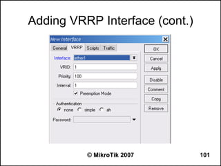
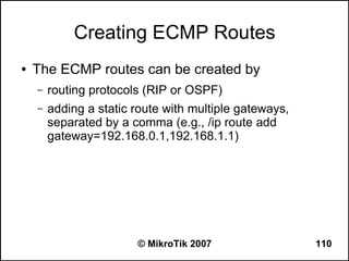
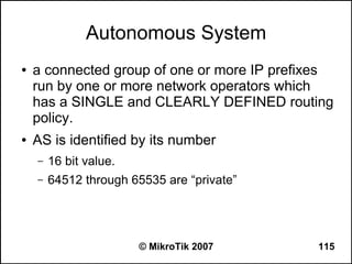
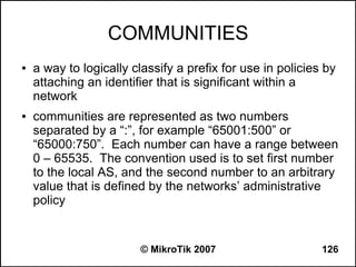
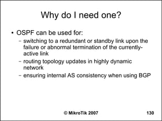
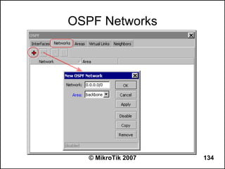
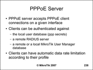
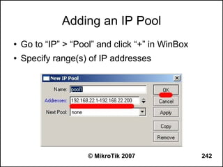
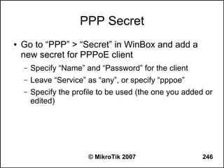
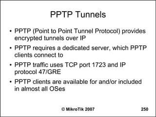
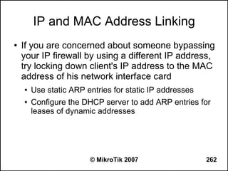
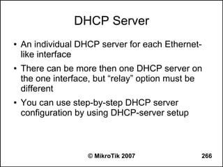
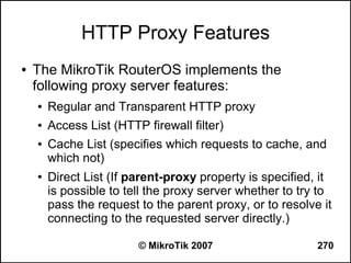
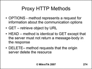
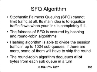
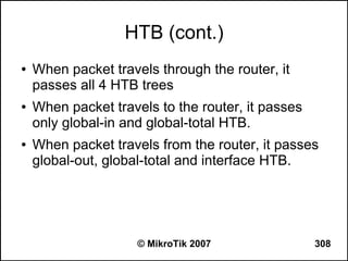
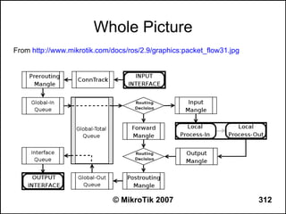
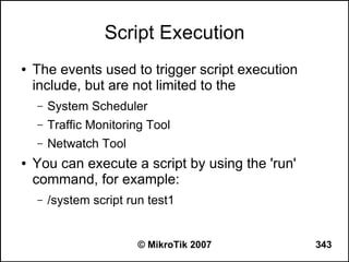
![Can you browse?
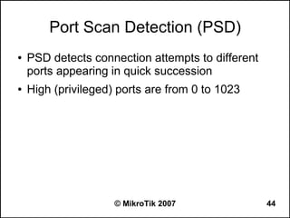
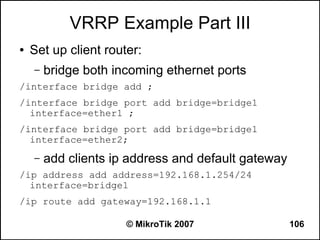
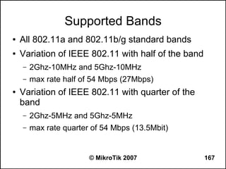
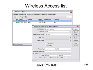
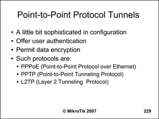
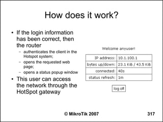
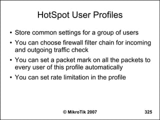
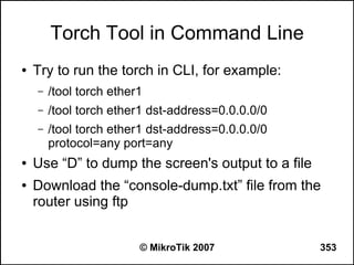
● Commands to use from the workstation:
– C:>tracert -d 8.8.8.8 (see how far it goes)
– C:>tracert -d google.com (does it resolve the name
to an IP address?)
– C:>ipconfig /all (are the IP address, netmask,
gateway correct, what is the DNS server?)
● Commands to use from the router:
– [john@22_John] > tool traceroute 8.8.8.8
– [john@22_John] > tool traceroute google.com
© MikroTik 2007 236](https://image.slidesharecdn.com/mikrotikadvancedtraining-130131071147-phpapp01/85/Mikro-tik-advanced-training-236-320.jpg)
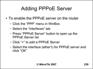
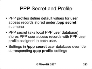
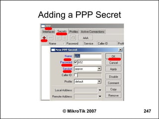
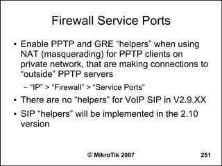
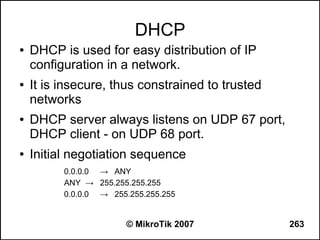
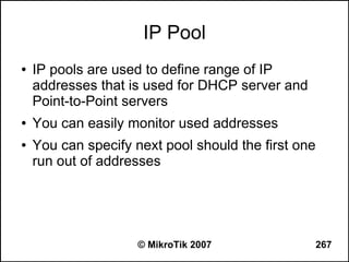
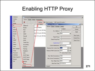
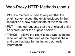
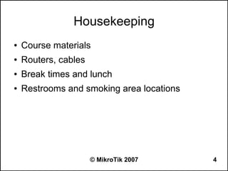
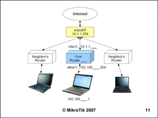
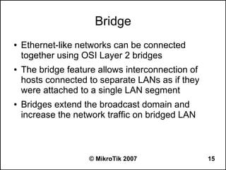
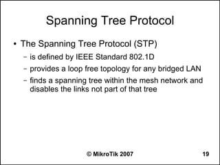
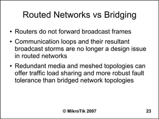
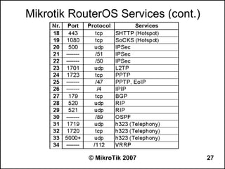
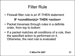
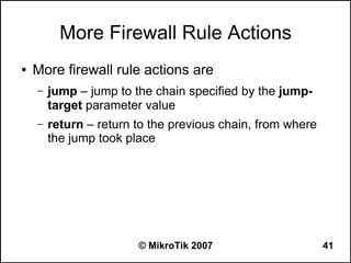
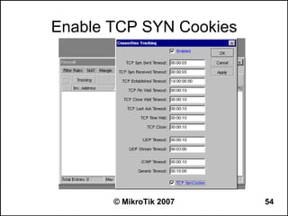
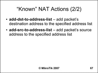
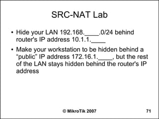
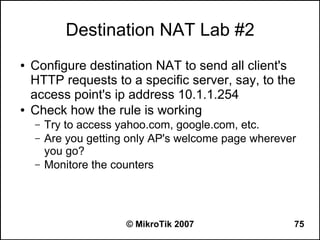
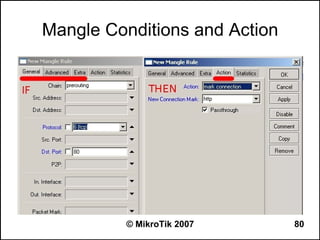
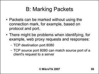
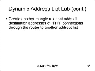
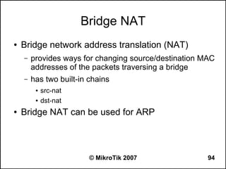
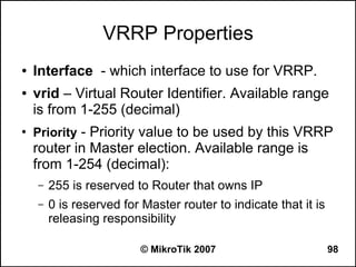
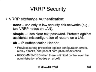
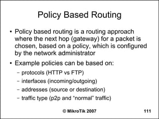
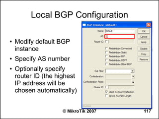
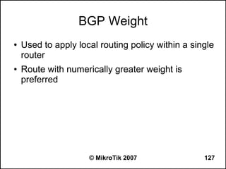
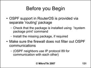
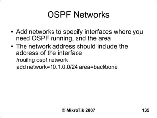
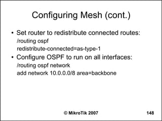
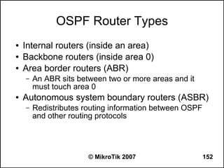
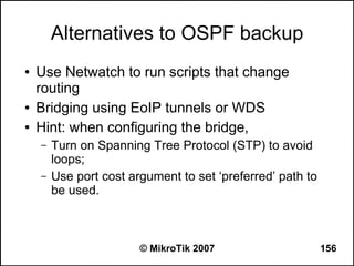
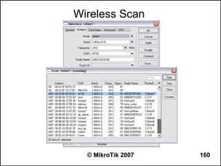
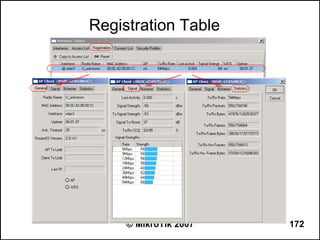
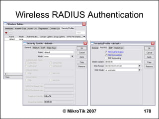
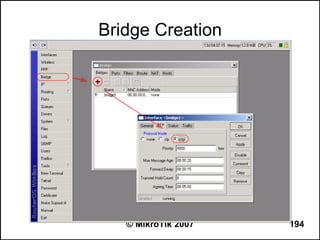
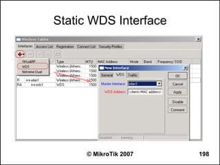
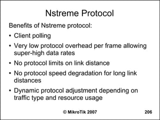
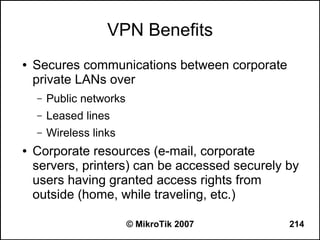
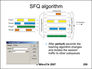
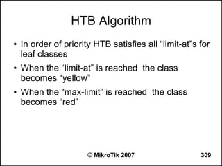
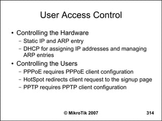
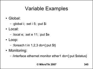
![Regular Expression Mode
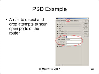
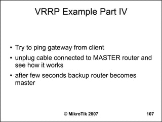
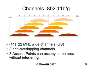
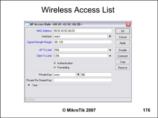
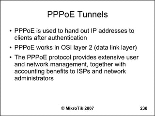
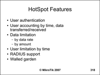
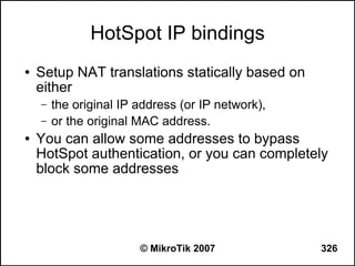
● Place a colon “:” at the beginning to enable
regular expression mode
● ”^“ - show that no symbols are allowed before the
given pattern
● “$“ - show that no symbols are allowed after the
given pattern
● “[....]” - A character class matches a single
character out of all the possibilities offered by the
character class
● (backslash) followed by any of [^$.|?*+() suppress
their special meaning.
© MikroTik 2007 277](https://image.slidesharecdn.com/mikrotikadvancedtraining-130131071147-phpapp01/85/Mikro-tik-advanced-training-277-320.jpg)


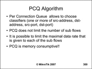


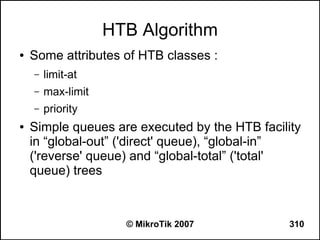

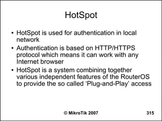

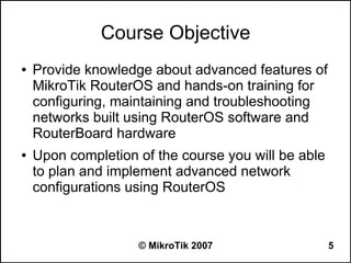
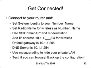
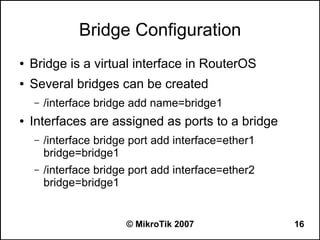
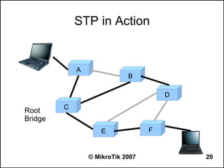
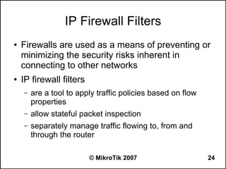
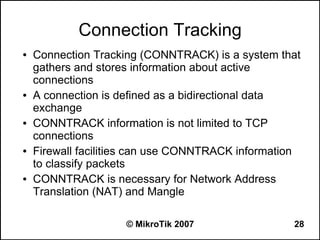
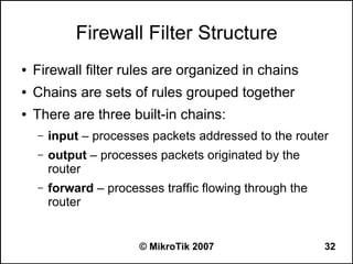
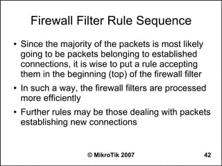
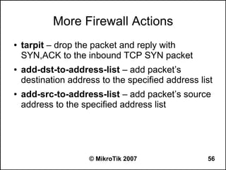
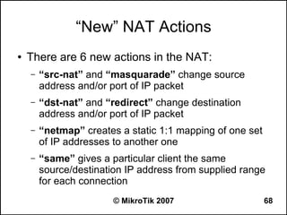
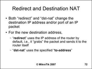
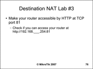
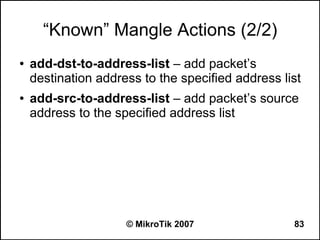
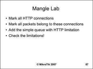
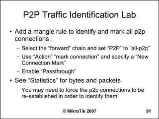
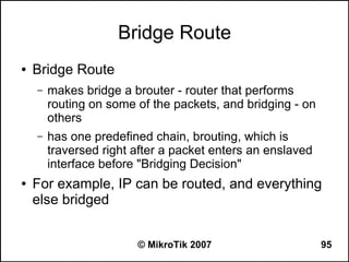
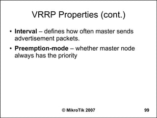
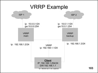
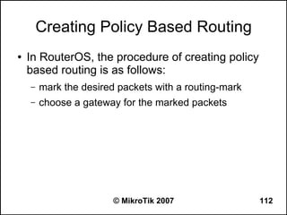
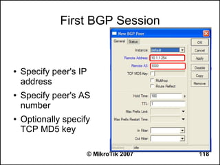
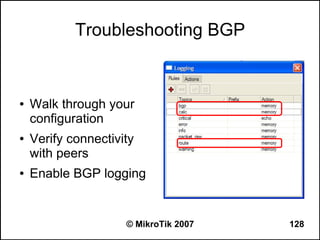
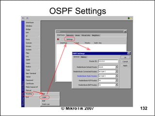
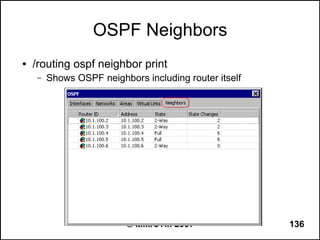
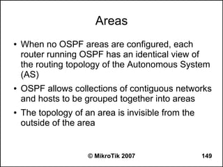
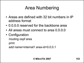
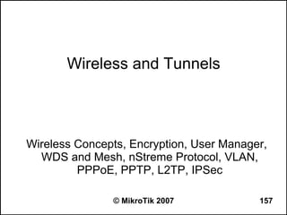
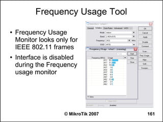
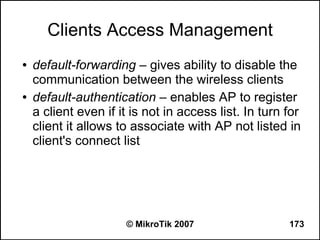
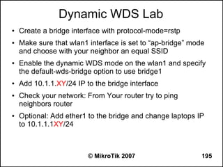
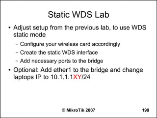
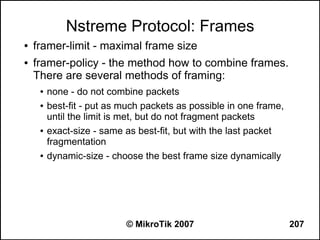
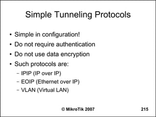
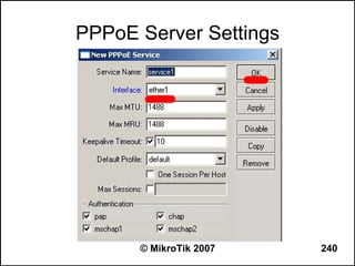
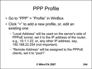
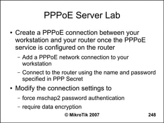
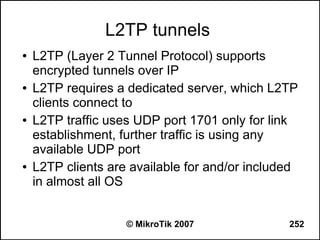
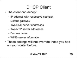
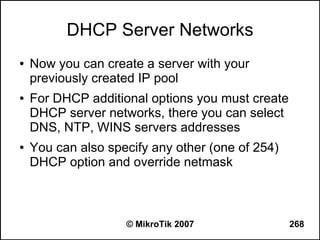
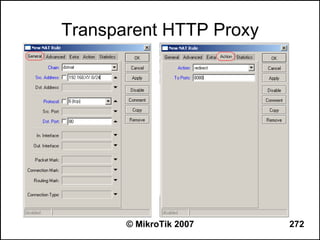
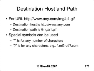
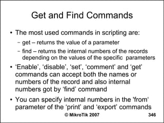
![Writing a Script
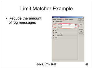
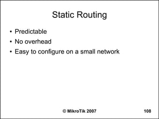
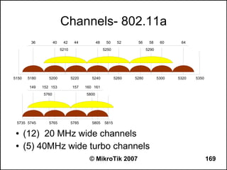
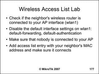
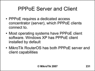
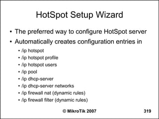
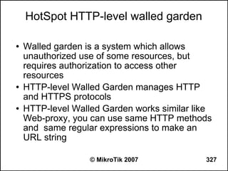
● Use ‘/system script’ menu to add a script
● Example:
– /system script add name=test1 source={:log info
“Hello, World!”}
● Write a script directly from command line
● Example:
– [admin@MikroTik] >:log info “Hello, World!”
© MikroTik 2007 342](https://image.slidesharecdn.com/mikrotikadvancedtraining-130131071147-phpapp01/85/Mikro-tik-advanced-training-342-320.jpg)


Here are the steps to disable MAC-WinBox and MAC-Telnet on all interfaces except the local interface: /ip service disable mac-telnet /ip service disable mac-winbox interface=all /ip service enable mac-winbox interface=local This will disable MAC-Telnet on all interfaces and disable MAC-WinBox on all interfaces except the local interface, improving security as recommended.