Downloaded 280 times
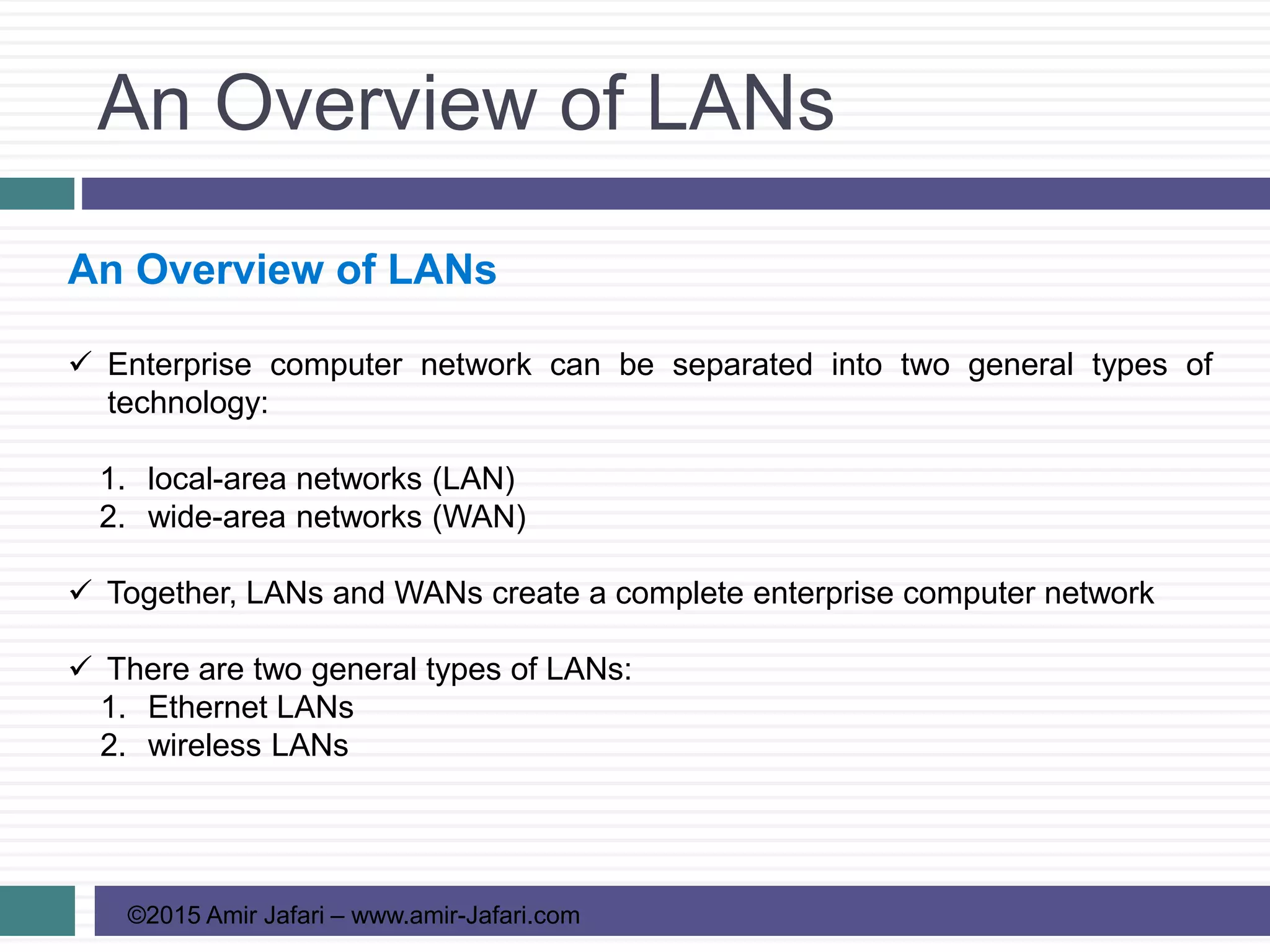
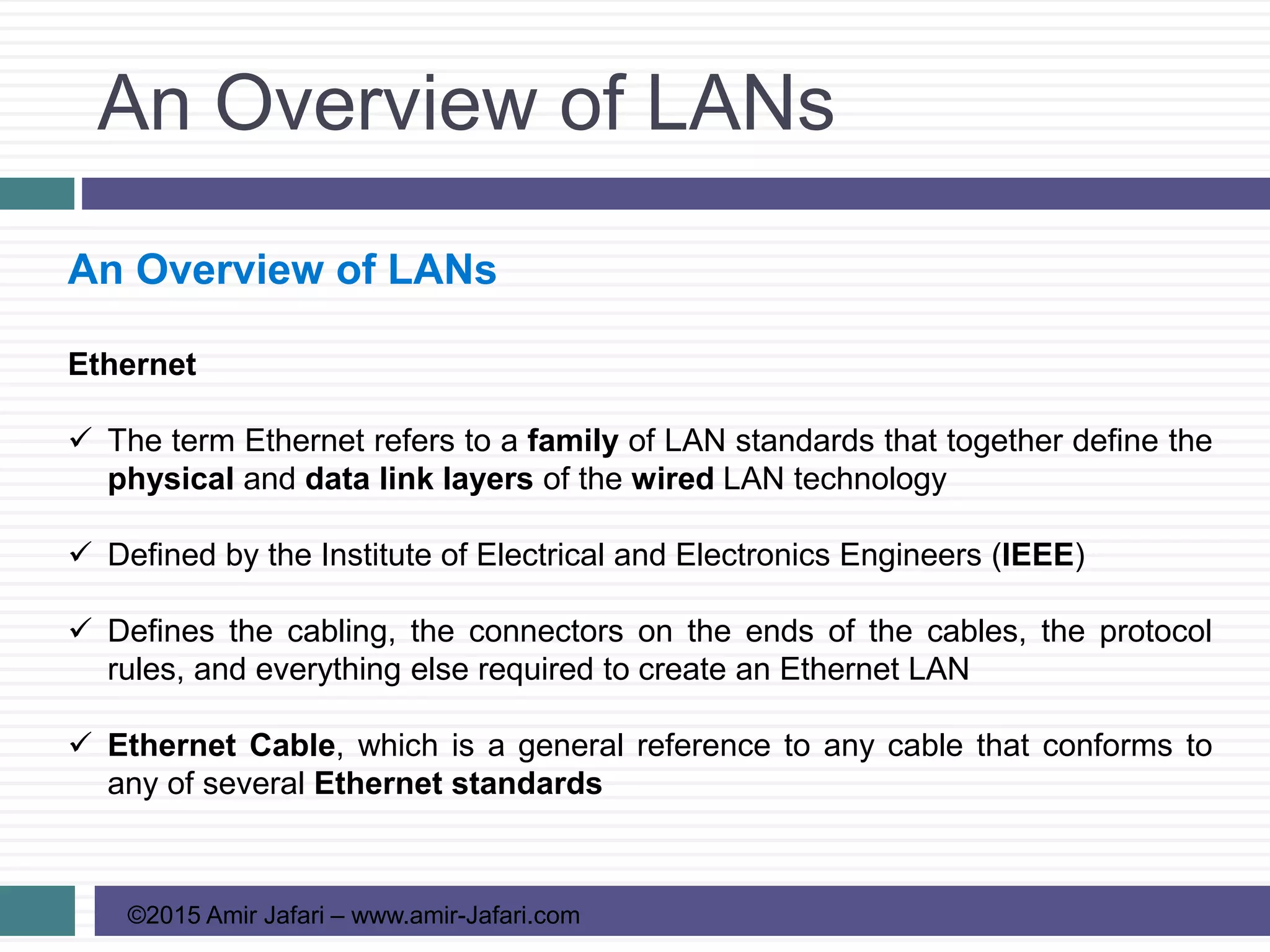
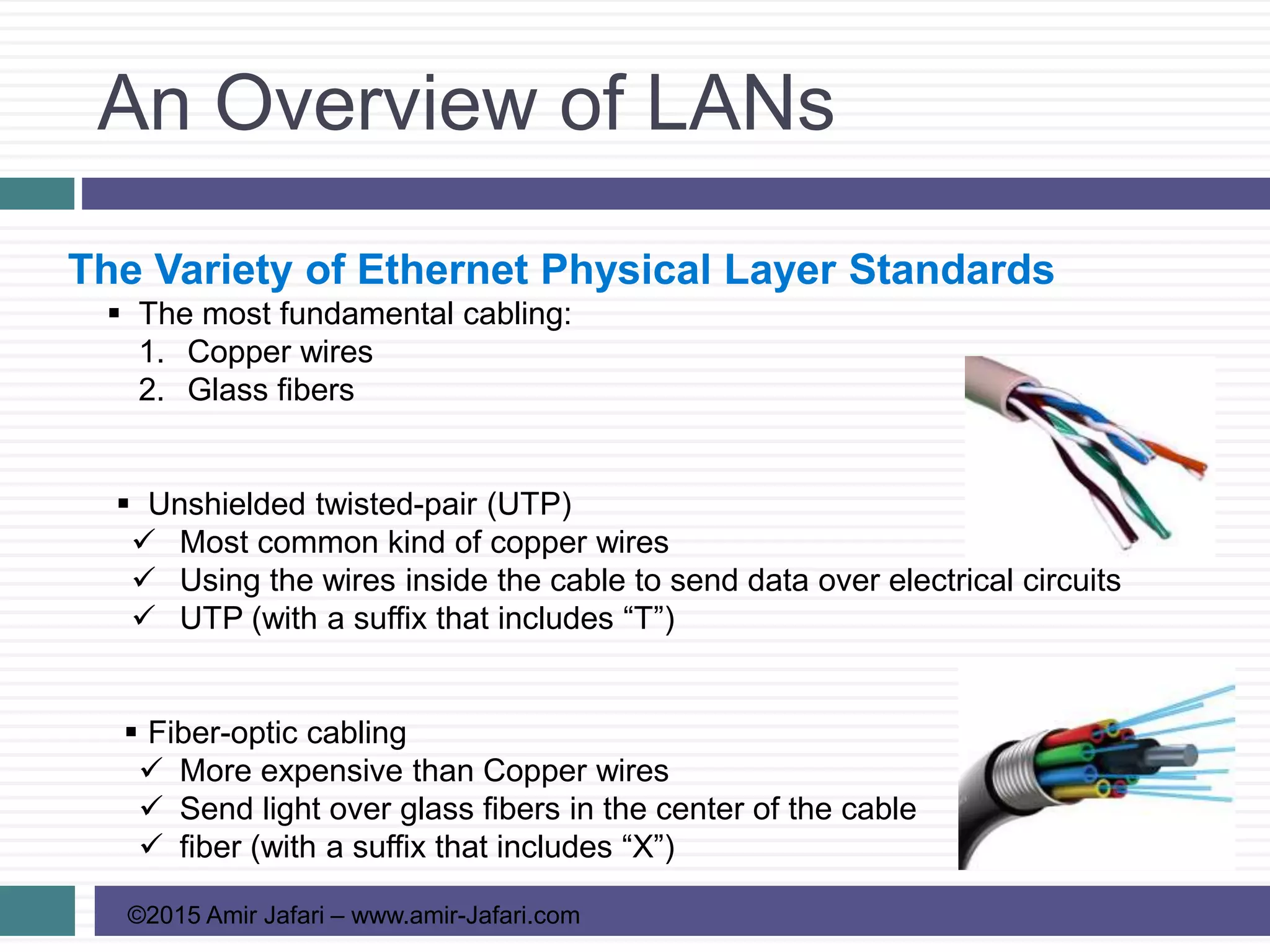
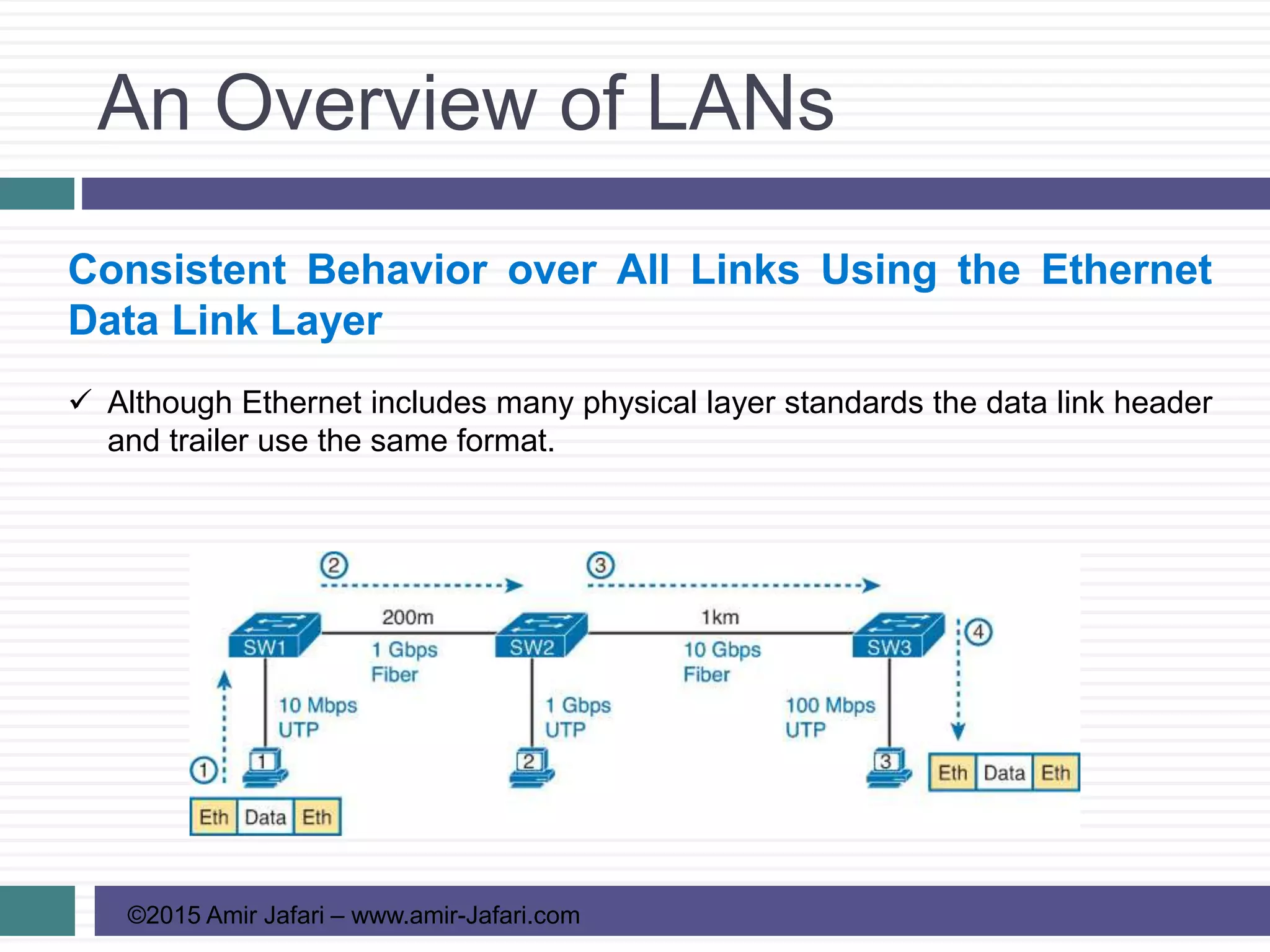
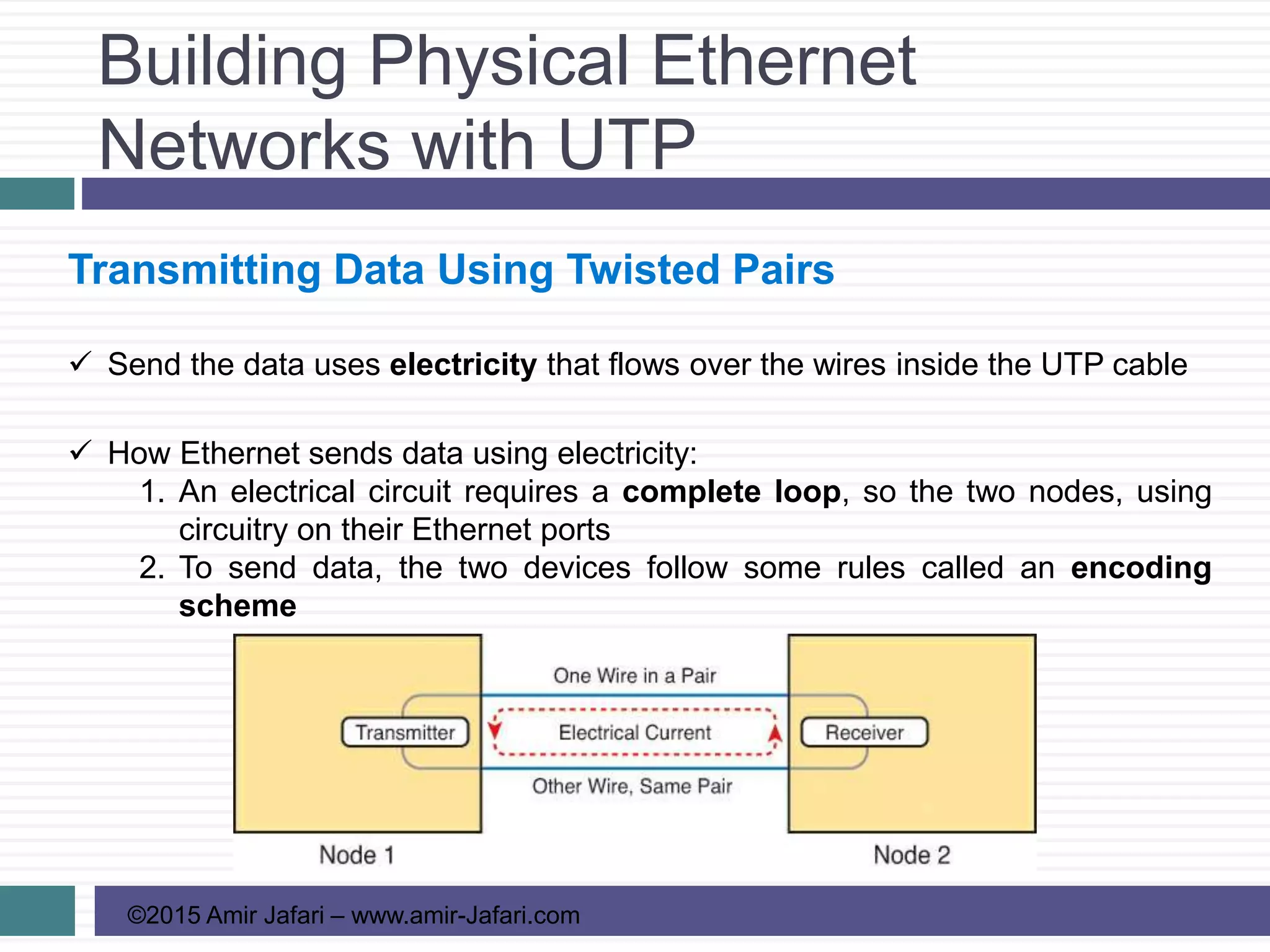
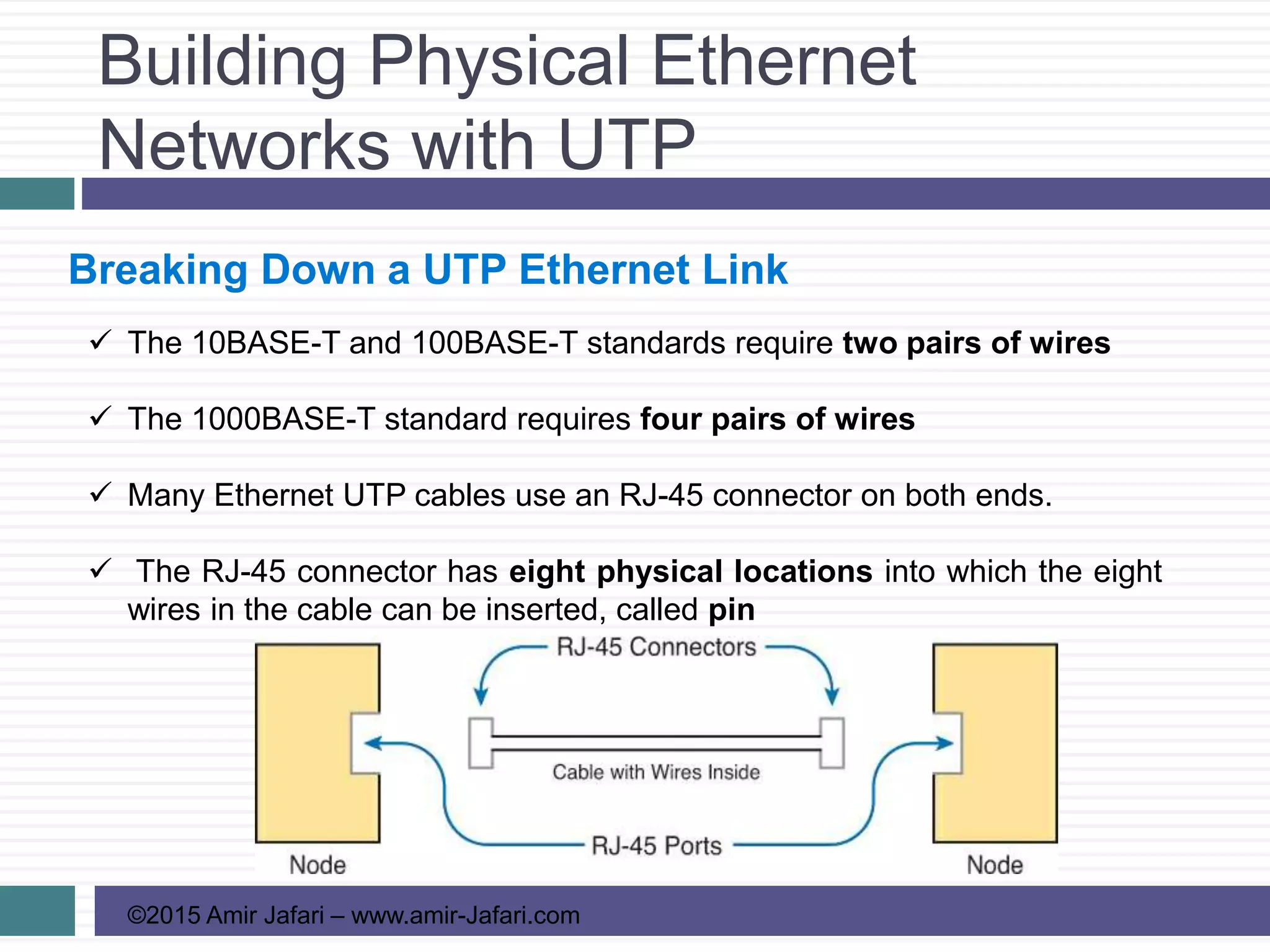
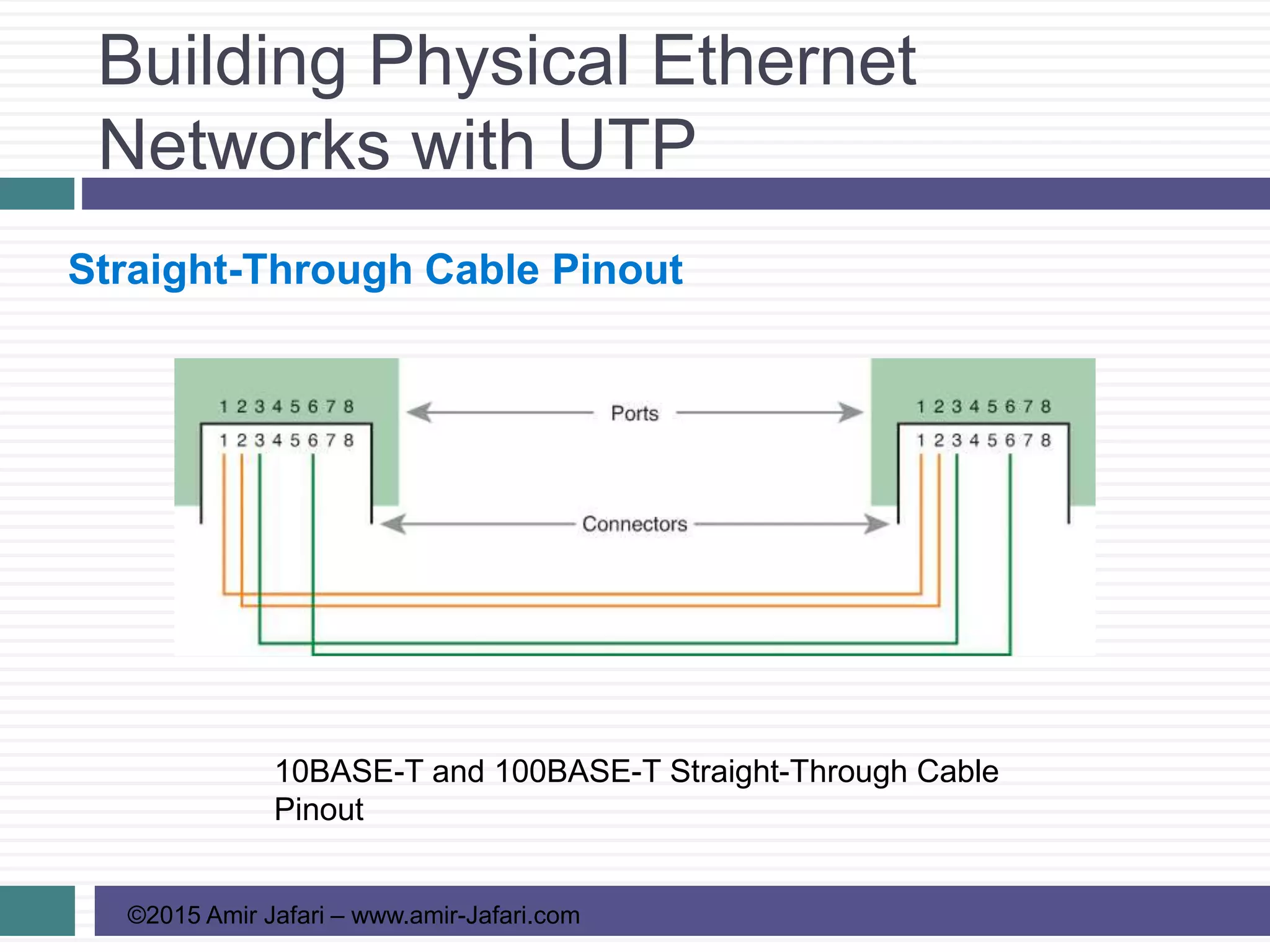
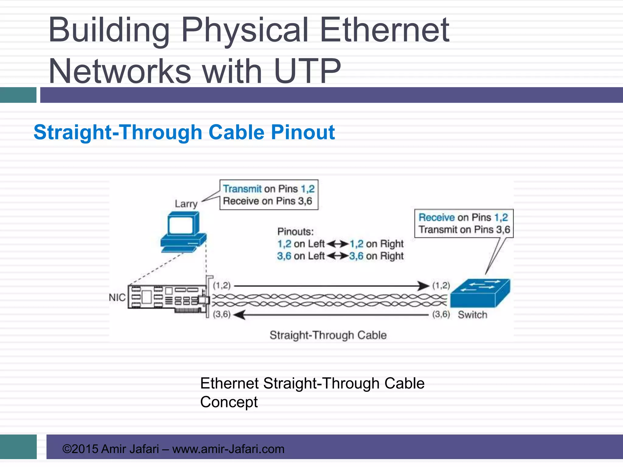
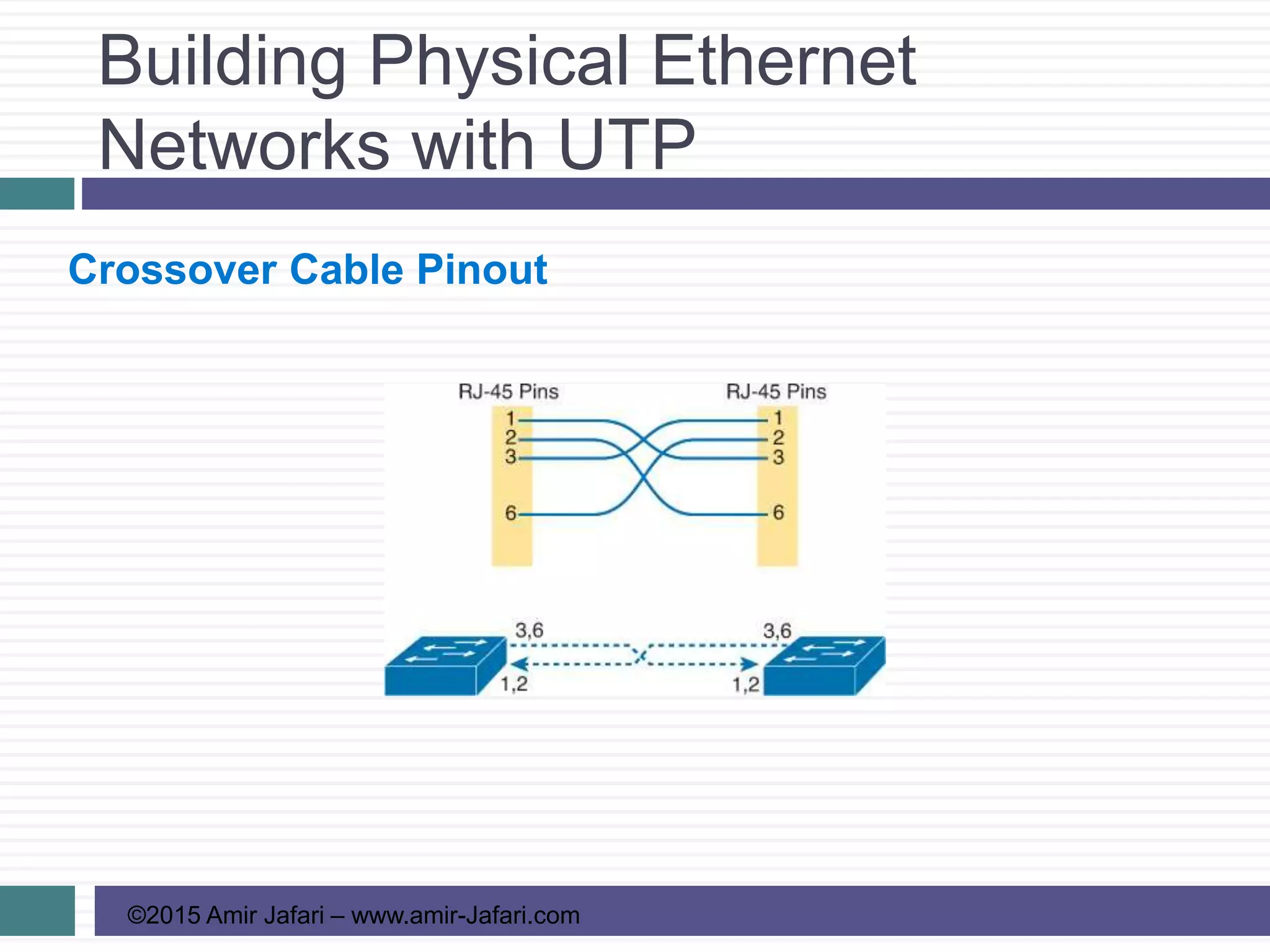
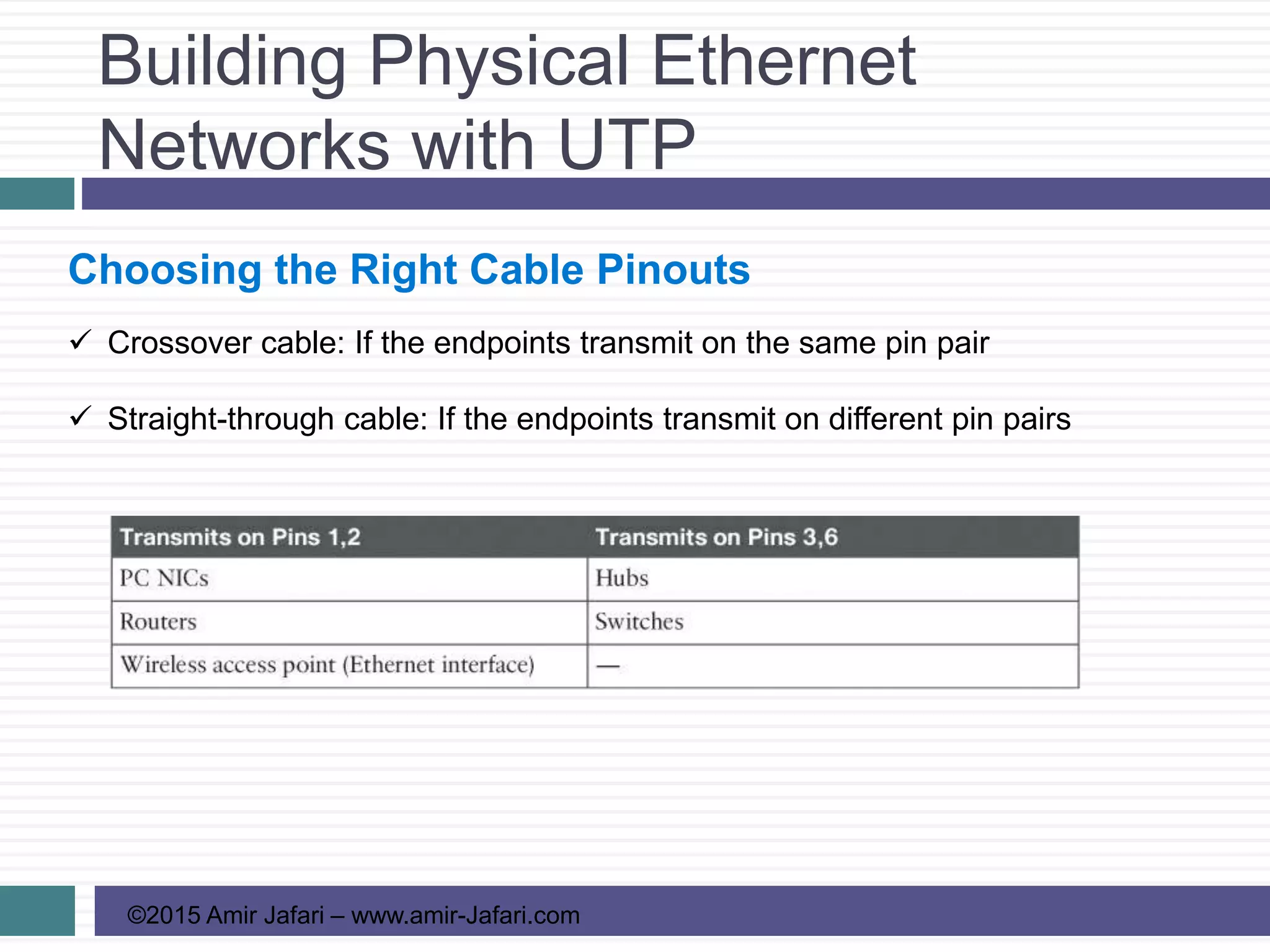
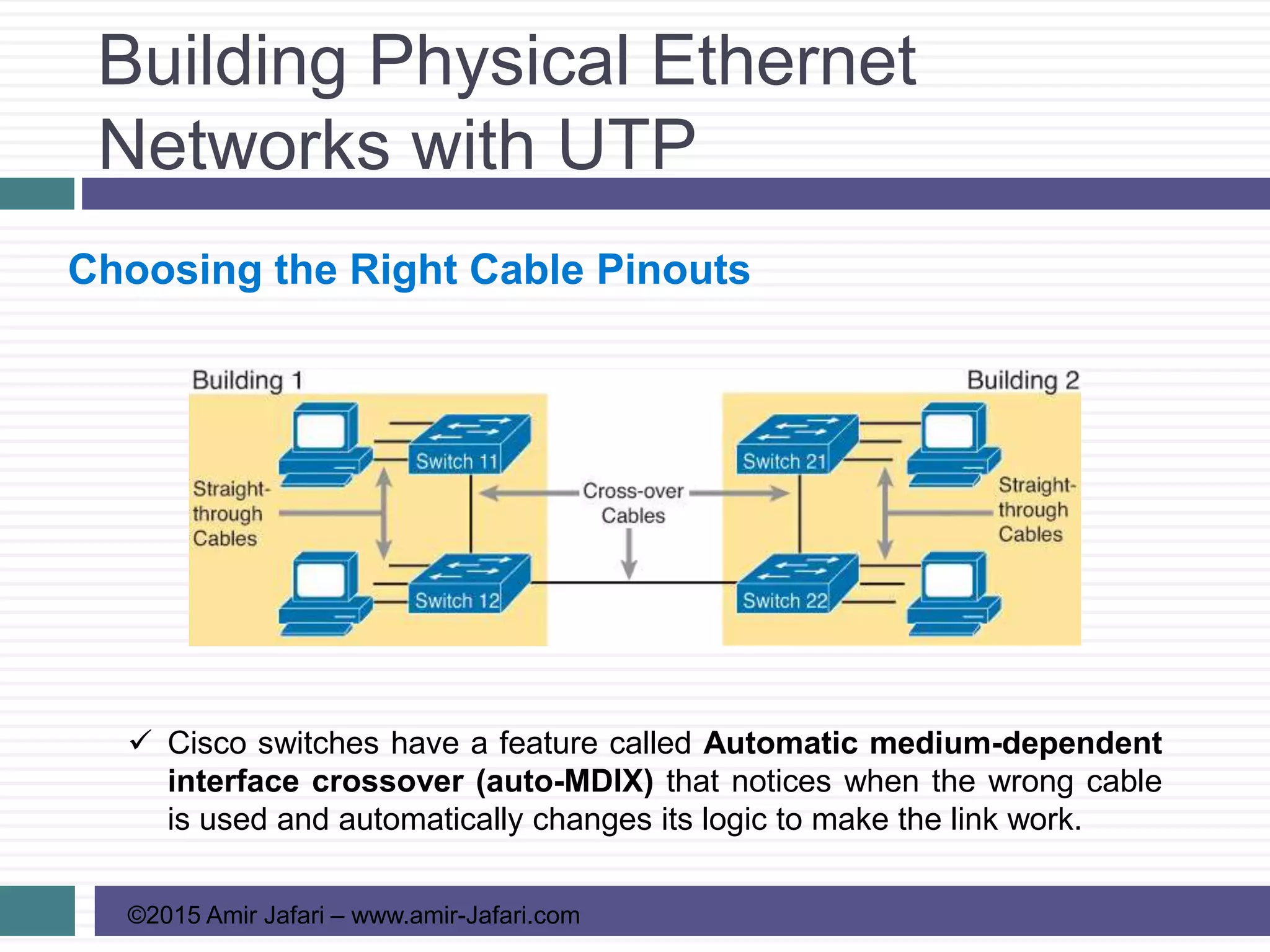
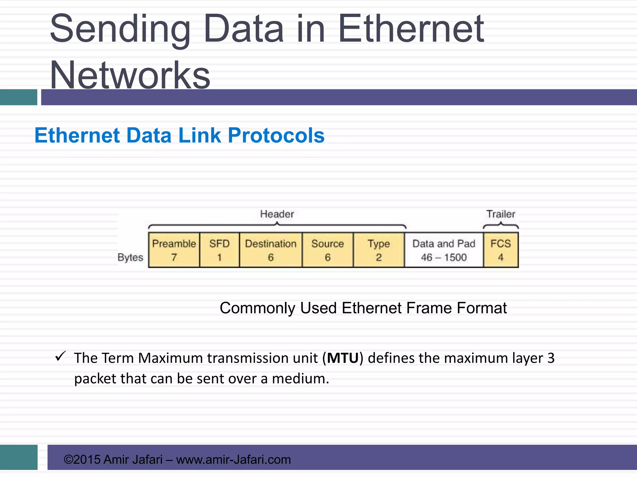
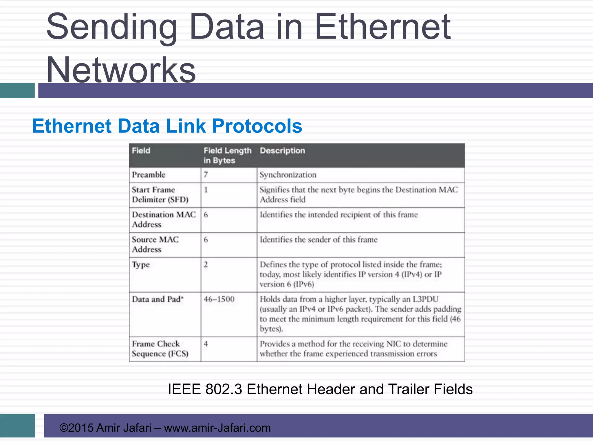
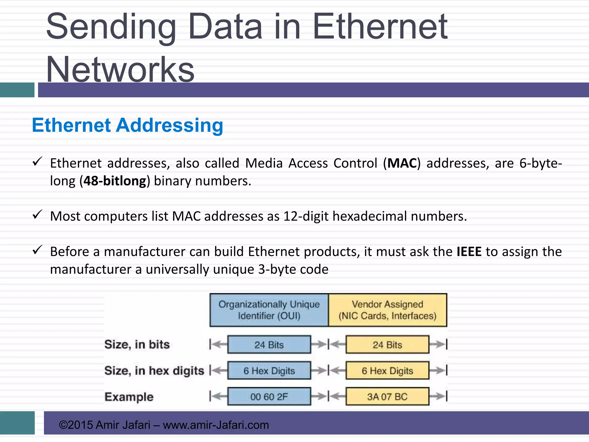

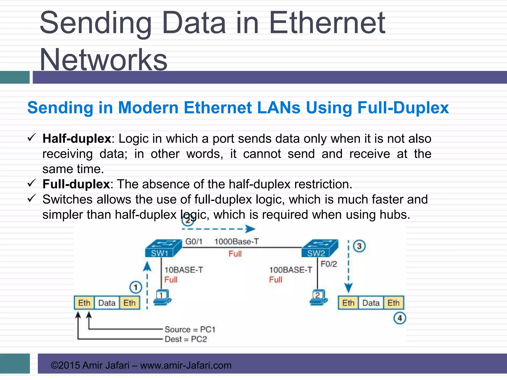
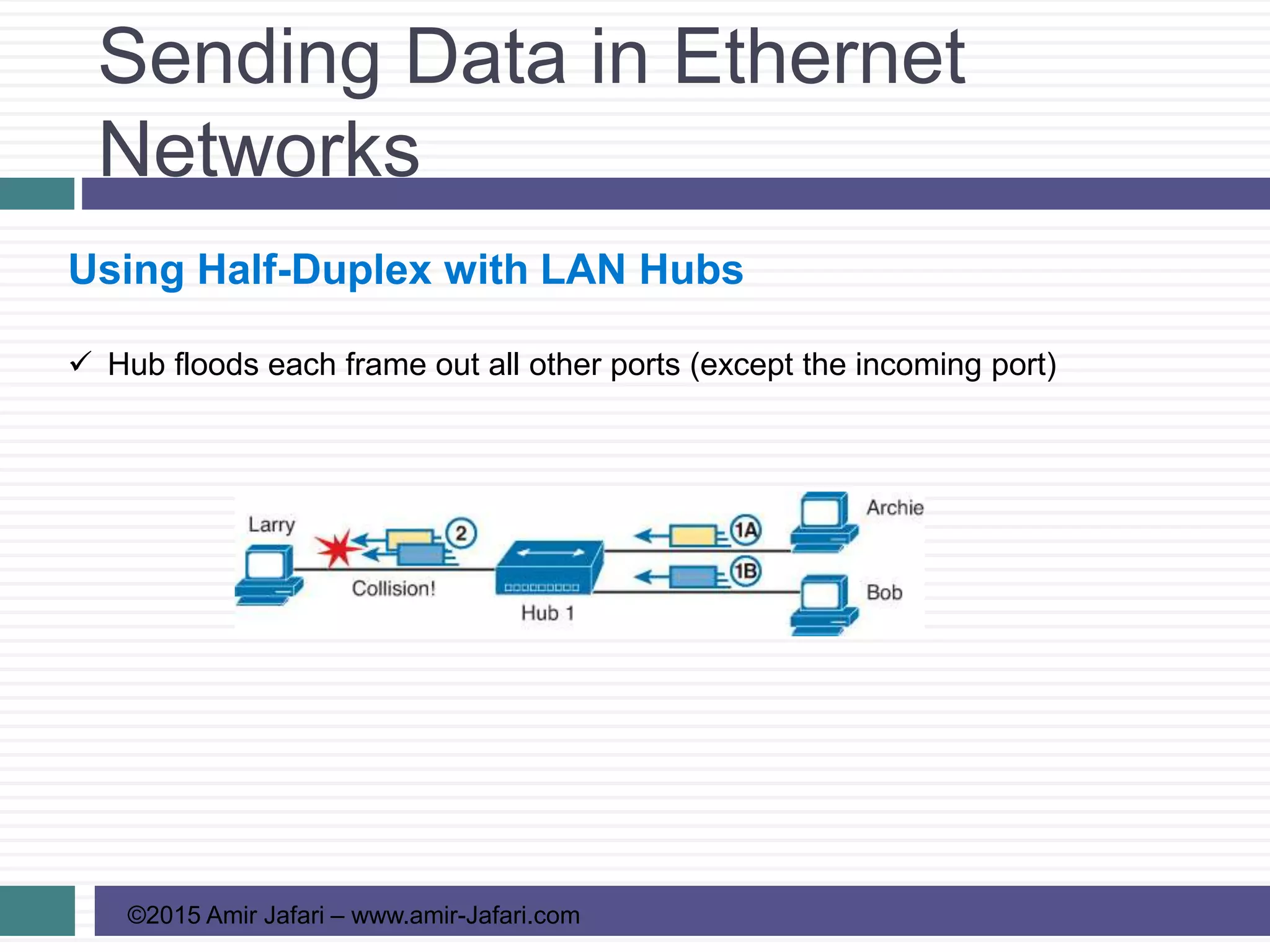
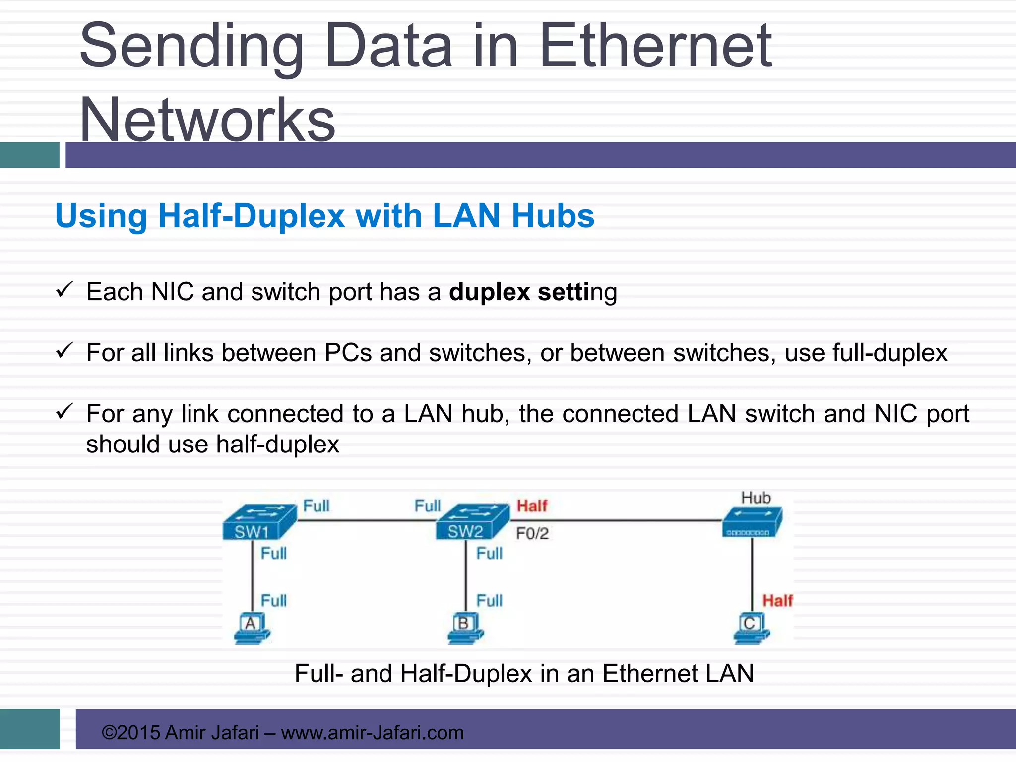

This document discusses fundamentals of Ethernet LANs, including: - An overview of LANs and the differences between Ethernet and wireless LANs. - How physical Ethernet networks are built using UTP cabling and the standards for transmitting data over copper wire pairs. - How Ethernet frames are formatted and the fields used for addressing, error detection, and identifying network layer protocols. - How data is sent in modern Ethernet LANs using full-duplex mode between switches versus half-duplex with hubs.
![Ccnp presentation [Day 1-3] Class](https://cdn.slidesharecdn.com/ss_thumbnails/ccnppresentation-day1-3demo-200416075108-thumbnail.jpg?width=640&height=640&fit=bounds)


![Coded Agents – with UiPath SDK + LangGraph [Virtual Hands-on Workshop]](https://cdn.slidesharecdn.com/ss_thumbnails/codedagentsdeck-251215155422-5497c599-thumbnail.jpg?width=640&height=640&fit=bounds)


