Downloaded 210 times
![Analyzing Switch Interface Status
©2015 Amir Jafari – www.amir-Jafari.com
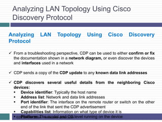
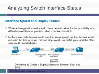
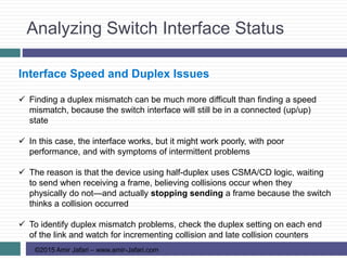
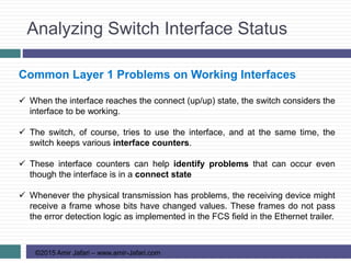
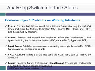
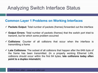
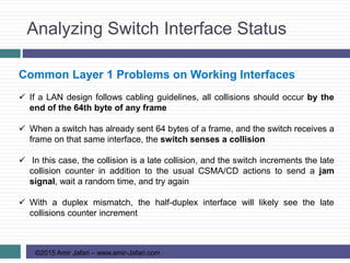
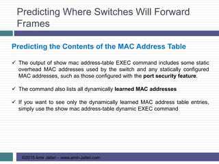
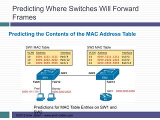
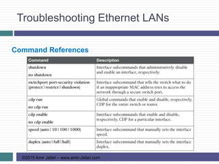
Common Layer 1 Problems on Working Interfaces
The receiving device discards the frame and counts it as some kind of input
error. Cisco switches list this error as a CRC error. (Cyclic redundancy check
[CRC] is a term related to how the FCS math detects an error)
Interface Counters for Layer 1 Problems](https://image.slidesharecdn.com/ccnars-11-troubleshootingethernetlans-150829124836-lva1-app6891/85/CCNA-R-S-11-Troubleshooting-Ethernet-LANs-25-320.jpg)
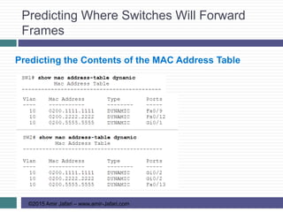
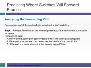
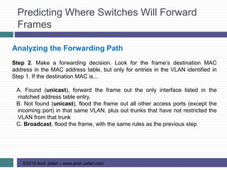
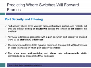

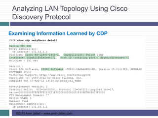
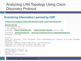
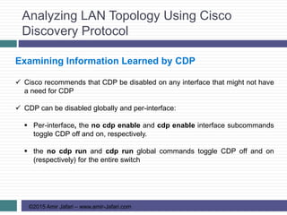
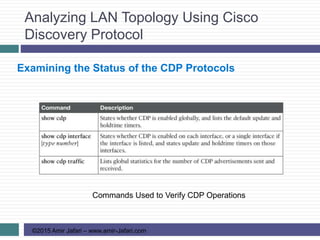
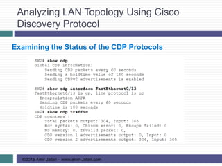
This document provides an overview of troubleshooting Ethernet LANs. It discusses perspectives on network verification and troubleshooting processes. It also covers analyzing LAN topology using Cisco Discovery Protocol, analyzing switch interface status including speed and duplex issues, predicting frame forwarding using MAC address tables, and analyzing VLANs and VLAN trunks.