Download as PDF, PPTX
![STP Configuration and Verification
©2015 Amir Jafari – www.amir-Jafari.com
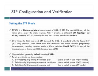
Per-VLAN Port Costs
Each switch interface defaults its per-VLAN STP cost based on the IEEE
recommendations.
On interfaces that support multiple speeds, Cisco switches base the cost on the current
actual speed.
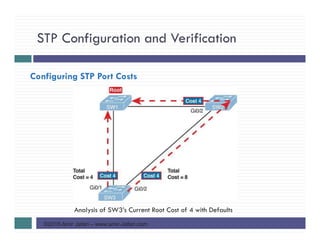
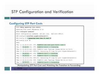
Alternatively, you can configure a switch’s STP port cost with the spanning-tree [vlan
vlan-id] cost cost interface subcommand
This command most often on trunks because setting the cost on trunks has an impact on
the switch’s root cost, whereas setting STP costs on access ports does not](https://image.slidesharecdn.com/ccnars-13-spanningtreeprotocolimplementation-150916113424-lva1-app6892/85/CCNA-R-S-13-Spanning-Tree-Protocol-Implementation-13-320.jpg)
![STP Configuration and Verification
©2015 Amir Jafari – www.amir-Jafari.com
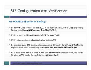
Per-VLAN Port Costs
For the spanning-tree [vlan vlan-id] cost cost, it can include the VLAN ID, or not.
The command only needs a vlan parameter on trunk ports to set the cost per VLAN.
On a trunk, if the command omits the VLAN parameter, it sets the STP cost for all
VLANs whose cost is not set by a spanning-tree vlan x cost command for that VLAN](https://image.slidesharecdn.com/ccnars-13-spanningtreeprotocolimplementation-150916113424-lva1-app6892/85/CCNA-R-S-13-Spanning-Tree-Protocol-Implementation-14-320.jpg)
![STP Configuration and Verification
©2015 Amir Jafari – www.amir-Jafari.com
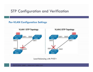
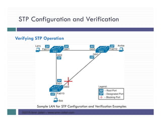
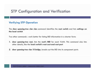
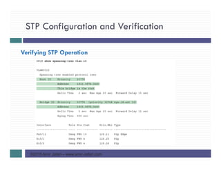
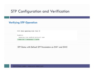
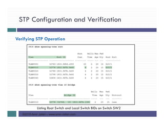
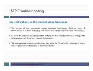
Verifying STP Operation
both the commands have a VLAN option:
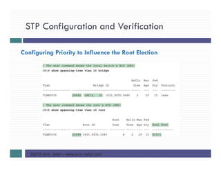
1. show spanning-tree [vlan x] root
2. show spanning-tree [vlan x] bridge
Without the VLAN listed, each command lists one line per VLAN
With the VLAN, the output lists the same information, but just for that one VLAN](https://image.slidesharecdn.com/ccnars-13-spanningtreeprotocolimplementation-150916113424-lva1-app6892/85/CCNA-R-S-13-Spanning-Tree-Protocol-Implementation-21-320.jpg)
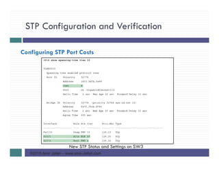
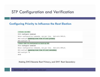
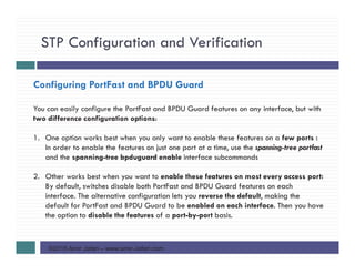
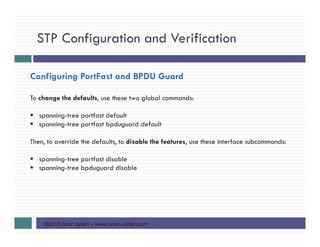
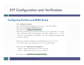
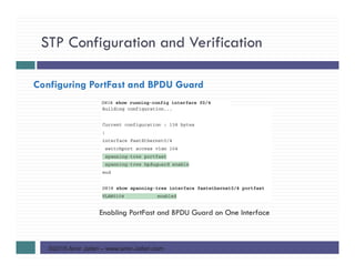
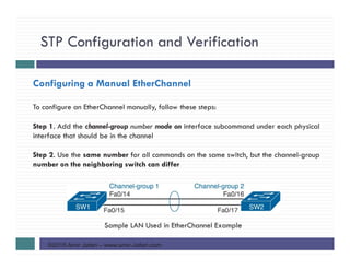
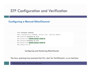
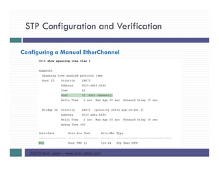
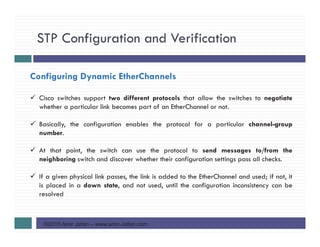
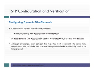
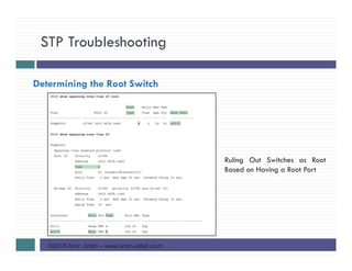
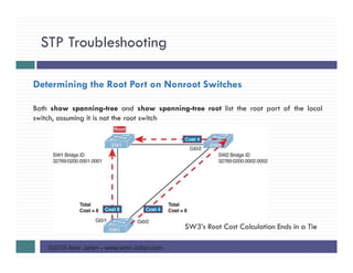
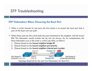
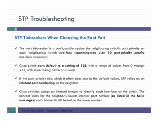
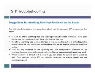
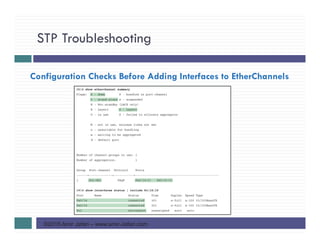

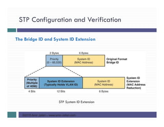
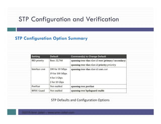
This document discusses configuration and verification of Spanning Tree Protocol (STP) on Cisco switches. It covers topics such as setting the STP mode, configuring port costs and priorities to influence the root election, enabling PortFast and BPDU guard, and configuring EtherChannel. Configuration examples are provided to demonstrate how to view STP status using show commands and manipulate the STP topology by adjusting port costs and switch priorities.