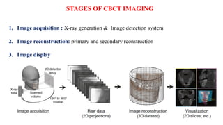
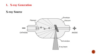
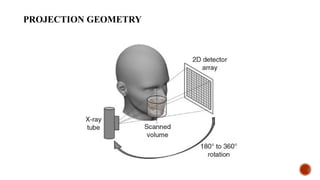
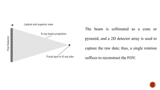
CONE-BEAM COMPUTED
TOMOGRAPHY
Presented by,
Dr. Nitha Willy
Second year post graduate
Department of Oral Medicine and Radiology
֎Also known as :
• Dental Volumetric Tomography
• Cone-beam Volumetric Tomography
• Dental Computed Tomography
• Cone-beam Imaging
֎Cone beam computed tomography (CBCT) was discovered in Italy in 1997.
֎The first unit created was the NewTom.
INTRODUCTION
PRINCIPLES OF CONE-BEAM COMPUTED TOMOGRAPHY
֎Uses a cone shaped divergent beam of ionizing radiation like X-rays and a 2D area
detector mounted on a rotated gantry to acquire multiplanar sequential projection
images in one single scan around the area of interest
֎Multiple planar projections are acquired by rotational scan to produce a volumetric
dataset from which interrelational images can be generated.
The technical elements for optimal imaging in CBCT comprise a sequence of discrete
but interrelated processes, referred to as the imaging chain. These include:
• A source of X-radiation.
• The object to be imaged
• A device capable of detecting the remnant radiation after attenuation by the object.
• A mechanism to archive the resultant image.
• A method to retrieve and display the image.
STAGES OF CBCT IMAGING
1. Image acquisition : X-ray generation & Image detection system
2. Image reconstruction: primary and secondary rconstruction
3. Image display
IMAGE ACQUISITION
1. X-ray Generation
X-ray Source
PROJECTION GEOMETRY
The beam is collimated as a cone or
pyramid, and a 2D detector array is used to
capture the raw data; thus, a single rotation
suffices to reconstruct the FOV.
 During the rotation, many exposures are made at fixed intervals, providing
single projection images known as basis images .
 The complete series of basis images is referred to as the projection data .
11
SCAN VOLUME
Also called as field of view
It is the amount of area to be exposed in a single scan.
Depends on:
Detector size
Geometry of beam projection
Collimation of the beam
Shape – cylinder or Spherical: Can be selected based on individual requirements.
IMAGE DETECTOR
CBCT units use either an image intensifier (II) or one of several types of flat panel detectors
(FPD) as the image detector
• II Based systems
• Indirect FPD systems
• Direct FPD systems
2. IMAGE DETECTION SYSTEM
II BASED SYSTEMS
• The attenuated X-ray beam is converted into electrons These electrons are
then amplified before being reconverted into photons, which are recorded using a charge-
coupled device (CCD).
• These systems tend to be relatively large and most frequently result in circular basis image
areas (spherical volumes) rather than rectangular ones (cylindrical volumes).
• They are prone to geometric distortion and have a relatively narrow dynamic range
INDIRECT FPD SYSTEMS
An indirect system consists of two components:
1. a scintillator medium which converts X-ray radiation into visible light
2. a photon detector which converts light into an electrical signal, which can then be digitized
DIRECT FPD SYSTEMS
FPD systems currently comprise
• an amorphous selenium (a-Se)
• Cadmium telluride (CdTe)
• cadmium zinc telluride (CdZnTe) photoconductor
which converts X-ray photons into an electrical charge, directly connected to a TFT or CMOS
panel.
For each projection image during acquisition, the detector receives incident X-ray
photons, collects a charge proportionally to the X-ray intensity at a given point, and sends
a signal to the computer. The speed with which a detector performs this acquisition is
called the frame rate.
FRAME RATE
• Frame rate is measured in frames, projected images, per second.
• The maximum frame rate of the detector and rotational speed determines the
number of projections that may be acquired.
• The number of projection images comprising a single scan may be fixed or
variable.
With a higher frame rate
• More information to reconstruct the image; therefore, primary reconstruction time is
increased.
• Increase the signal-to-noise ratio, producing images with less noise.
• In the maxillofacial region, it reduces metallic artifact.
• Usually accomplished with a longer scan time and hence higher patient dose.
VOXELS
• Voxels are three-dimensional data blocks that representing a specific x-ray absorption.
• CBCT units capture isotropic voxels.
• An isotropic voxel is equal in all three dimensions (x, y, and z planes) producing higher
resolution images.
• The voxel sizes currently available in CBCT units range from 0.076 mm to 0.4 mm.
Resolution of the final image is determined by the unit’s voxel size.
 The smaller the voxel size the higher the resolution.
 The higher the resolution, the higher the radiation dose to the patient as well.
The principal determinants of nominal voxel size in CBCT are
 the x-ray tube focal spot size
 x-ray geometric configuration
 the matrix and pixel size of the solid state detector
 CBCT images are reconstructed as a 3D stack of voxels, in which each voxel is
assigned a grey value (i.e., a whole number) according to its estimated X-ray
attenuation.
 A lower grey value corresponds to a lower attenuation, with the lowest grey values
corresponding to air.
GREY VALUES
 The ability of CBCT to display differences in attenuation is related to the ability of the
detector to detect subtle contrast differences.
 This parameter is called the bit depth of the system and determines the number of
shades of gray available to display the attenuation.
 All available CBCT units used detectors capable of recording grayscale differences of
12 bits or higher.
 If a 12-bit detector is used to define the scale, 4096 shades are available to display
contrast.
DATA ACQUISITION
The patient is positioned with the unit.
The equipment orbits around the patient in a 180°, 270° or 360° rotation, taking
approximately 5–40 seconds, and in one cycle or scan, images a cylindrical or spherical
volume referred to as the field of view (FOV).
As all the information/data is obtained in the single scan, the patient must remain stationary
throughout the exposure.
IMAGE RECONSTRUCTION
The reconstruction process consists of:
 Primary reconstruction
 Secondary or multiplanar reconstruction
 The most widely used reconstruction algorithm in CBCT is the Feldkamp
(FDK) algorithm, which is a modified filtered backprojection (FBP) method.
 When a larger number of projection angles are combined, the reconstruction
represents the original object more accurately.
To facilitate reconstruction, data is often acquired by one computer (acquisition computer)
and transferred via ethernet connection to a second computer (workstation) for processing.
Reconstruction times vary depending on the
• Acquisition parameters (voxel size, FOV, number of projections)
• Hardware (processing speed, data put from acquisition to workstation computer)
• Software (pre- and post-processing, reconstruction algorithm) used.
Reconstruction should be accomplished in usually less than 5 min
PRIMARY RECONSTRUCTION
 Having obtained data from the one scan, the computer then
divides the volume into tiny cubes or voxels (ranging in
size between 0.076 mm3 and 0.4 mm3) and calculates the
X-ray absorption in each voxel.
 Each voxel is allocated a number and then allocated a
colour from the grey scale from black through to white.
 Typically one scan contains over 100 million voxels.
SECONDARY OR MULTIPLANAR RECONSTRUCTION
• The axial plane (X) is a horizontal plane that divides
the anatomical features within the FOV into superior
and inferior slices
• The coronal plane (Y) is a vertical plane that divides
the anatomical features within the FOV into anterior
and posterior slices
• The sagittal plane (Z) is also a vertical plane that
divides the anatomical features within the FOV into
right and left slices
AXIAL
Images in the axial orthogonal plane demonstrate a continuum of anatomy
extending from the supraorbital region of the frontal bone to the hyoid bone
and vertebral bodies of the third cervical vertebrae.
CORONAL
Images in the coronal orthogonal plane demonstrate facial and cranial anatomy
extending from supraciliary arches of the frontal bone and mental protuberance of
the mandibular symphysis to the occipital condyles of the occipital bone and
anterior processes of the cervical vertebrae.
SAGITTAL
Images in the sagittal orthogonal plane demonstrate a continuum of anatomy
extending from the midline of the nasal cavity and cranial base laterally to the
mastoid sinuses and glenoid fossa of the temporal bone and condylar head of the
mandible.
 Following the primary reconstruction, the computer software then allows the operator to
select voxels in the three anatomical orthogonal planes to create sagittal, coronal or axial
images
 A set of sagittal, coronal and axial images appear simultaneously on the computer
monitor.
 The software then enables these image data sets to be scrolled through in real time.
 For example, by selecting and moving the horizontal cursor up and down on the coronal
image, all the axial images can be scrolled through from top to bottom.
VOLUME ACQUISITION
CBCT units can be assigned into four broad categories based on the vertical and horizontal
dimensions of the FOV :
• Large (Maxillofacial)
• Dentoalveolar (both jaws)
• Single jaw/dual TMJ
• Small (localized)
Image Quality
Image quality can be described using four fundamental parameters:
• Spatial resolution
• Contrast resolution
• Noise
• Artifacts
IMAGE DISPLAY
There are four independent operations involved in image display for CBCT (Udupa 1999):
• Reconstruction
• Visualization
• Post-processing- Image enhancement and image manipulations
• Analysis
VISUALIZATION
The images from CBCT reconstruction are optimized to facilitate visual display
by various rendition techniques in both 2- and 3-D
POST-PROCESSING
In this operation, an observer interacts with the image to alter the representation of
features within the image dataset.
This involves specific image enhancement techniques.
ANALYSIS
The assessment of various image characteristics is performed to provide quantitative
information from the dataset
TECHNIQUE AND POSITIONING
Patient preparation
● Patients should be asked to remove any earrings, jewellery, hair pins, spectacles, dentures
or orthodontic appliances.
● The procedure and equipment movements should be explained to reassure patients and the
importance of remaining stationary throughout the scan should be stressed.
EQUIPMENT PREPARATION
● The smallest volume size needed to answer the clinical question should be used to
reduce the radiation dose to the patient. Using a smaller volume reduces scatter and
potentially improves image quality.
● Optimal exposure factors should be selected to satisfy the diagnostic requirements of
the examination. Higher exposure factors may be chosen if a higher spatial resolution is
required.
● Optimal reconstructed voxel size should be selected. If choosing a larger voxel size
results in a reduced patient dose (due to lower exposure factors being used) then this
should be considered as long as the lower resolution is compatible with the aims of the
radiographic examination.
● Some machines offer a ‘quick scan’ where the rotation arc is reduced. This feature
reduces the number of projections taken and therefore reduces the dose. If the required
diagnostic information can be obtained using this scan protocol then it should be selected.
Patient positioning
• The patient should be positioned using the manufacturer’s guidelines to ensure that
the correct region of interest is captured. A scout view may be useful to ensure the
right part of the jaw is imaged
• Once positioned correctly, using the light beam markers, immobilization chin cups
and head straps must be used to prevent any patient movement
• There is no need for the routine use of a protective lead apron.
• There is no need for the routine use of a protective thyroid collar as the thyroid
gland does not normally lie in the primary beam, however its use should be
considered on a case by case basis particularly in children.
• If used, it must be positioned so that it does not interfere with the primary beam
since this could lead to significant artefacts.
ARTIFACTS
Artifacts can be classified based on
1. Their appearance in the image :
• Streaks
• Shadings
• rings/bands
• miscellaneous
2. According to where they occur in the imaging chain
• image acquisition
• patient-related artifacts
• The scanner itself
• The beam projection geometry
Appearance of
artifact
Definition Possible causes
Streaks Intense straight lines (dark or
bright) across the image
Aliasing, partial volume, motion, metal,
beam hardening, noise, mechanical failure
Shadings Dark or bright areas, particularly
near objects of high contrast
Partial volume, beam hardening, scatter
radiation, incomplete projections
Rings/bands Rings (full or arcs) or bands
superimposed on the image
Calibration error, crude interpolation in the
reconstruction, offset projection
Miscellaneous Cupping, densitometric
inaccuracy
Beam hardening, scatter radiation,
reconstruction algorithm
IMAGE ACQUISITION ARTIFACTS
X-ray beam related
• Scatter
• Beam hardening
* Cupping
* Streaks and dark bands
• Extinction
• Exponential edge gradient effect
PATIENT-RELATED ARTIFACTS
• Patient motion during the CBCT gantry rotation can cause misregistration of data, and
most visibly appear as a “double contour”
• Subtler motion artifacts presenting as image unsharpness and loss of resolution may also
originate.
• Motion blur is a well-known artifact that, in the case of MDC, led to the development of
ultrafast acquisition times below 1 s
SCANNER-RELATED ARTIFACTS
Scanner-related artifacts present as circular or concentric dark
rings in the axial plane centered about the location of the axis of
rotation.
⁕ Partial Volume Effect
⁕ Sampling Artifacts
⁕ Cone Beam Effect
⁕ Local Tomography
⁕ Offset Projection
Advantages of Three-Dimensional Digital Imaging
1. Lower radiation dose
2. Brief scanning time
3. Anatomically accurate images
4. Ability to save and easily transport images
5. Very good spatial resolution
6. Compatible with implant and cephalometric planning software.
Disadvantages
1. The patient has to remain absolutely stationary throughout the scan to avoid
movement artefacts
2. Soft tissues not imaged in detail
3. Computer constructed panoramic type images are not directly comparable with
conventional panoramic radiographs – particular care is needed in their interpretation
4. Radiodense objects such as restorations and root filling materials can produce
artefacts
REFERENCES
1. Maxillofacial Cone Beam Computed Tomography- Principles, Techniques and Clinical
Applications: Scarfe
2. Eric Whaites Nicholas Drage Essentials of dental radiography and dental radiology
3. Interpretation basics of cone beam computed tomography
4. Dental Radiography- principles and techniques: Lannucci and Howerton-5th
edition
5. Textbook of dental and maxillofacial radiology- Freny radiology- 2nd
edition
6. White & Pharoah: 8th
edition
NORMALANATOMICAL LANDMARKS
AT THE SUPRA-
ORBITAL LEVEL
AT THE SUPERIOR-
ORBITAL LEVEL
AT THE MID-ORBITAL
LEVEL
AT THE INFERIOR
ORBITAL LEVEL
AT THE ZYGOMATIC
ARCH LEVEL
AT THE MID MAXILLARY
SINUS LEVEL
AT THE LEVEL OF THE
SUPERIOR PORTION OF
THE MAXILLARY
ALVEOLUS
AT THE LEVEL OF THE
MANDIBULAR FORAMEN
AT THE LEVEL OF THE
ALVEOLAR PROCESS OF
THE MANDIBLE
AT THE LEVEL OF THE
MENTAL FORAMEN
AT THE LEVEL OF THE
LOWER BORDER OF THE
ANTERIOR MANDIBULAR
SYMPHYSIS
AT THE LEVEL OF THE
FRONTAL SINUS AND
ANTERIOR TEETH
AT THE LEVEL OF THE
ANTERIOR MAXILLARY
SINUS AND PREMOLAR
TEETH
AT THE LEVEL OF THE
ANTERIOR ORBITAL RIM
AND ZYGOMATIC BONE
AT THE LEVEL OF THE
ZYGOMATIC ARCH AND
POSTERIOR TEETH
AT THE LEVEL OF THE
MIDDLE OF THE
MAXILLARY SINUS
AT THE LEVEL OF THE
MIDDLE OF THE
ZYGOMATIC ARCH AND
THIRD MOLARS
AT THE LEVEL OF THE
ANTERIOR SPHENOID
SINUS, MAXILLARY
TUBEROSITY AND THIRD
MOLARS
AT THE LEVEL OF THE
CORONOID PROCESS
AND PTERYGOID
PLATES
AT THE LEVEL OF THE
MANDIBULAR CONDYLES
AT THE LEVEL OF THE
BODY OF C1 AND
ODONTOID PROCESS OF
C2 OF THE UPPER
CERVICAL SPINE
MIDSAGITTAL
ORTHOGONAL CBCT
IMAGE
AT THE LEVEL OF THE
MIDDLE OF THE
RIGHT NASAL
APERTURE
AT THE LEVEL OF THE
NASOLACRIMAL DUCT
AT THE LEVEL OF THE
MEDIAL WALL OF THE
RIGHT MAXILLARY SINUS
AT THE LEVEL OF
THE MEDIAL WALL
OF THE RIGHT
MAXILLARY SINUS
AT THE LEVEL OF THE
RIGHT INFRAORBITAL
FORAMEN
CBCT basic principle,artifacts,landmarks.pptx

CBCT basic principle,artifacts,landmarks.pptx

  • 1.
    CONE-BEAM COMPUTED TOMOGRAPHY Presented by, Dr.Nitha Willy Second year post graduate Department of Oral Medicine and Radiology
  • 2.
    ֎Also known as: • Dental Volumetric Tomography • Cone-beam Volumetric Tomography • Dental Computed Tomography • Cone-beam Imaging ֎Cone beam computed tomography (CBCT) was discovered in Italy in 1997. ֎The first unit created was the NewTom. INTRODUCTION
  • 3.
    PRINCIPLES OF CONE-BEAMCOMPUTED TOMOGRAPHY ֎Uses a cone shaped divergent beam of ionizing radiation like X-rays and a 2D area detector mounted on a rotated gantry to acquire multiplanar sequential projection images in one single scan around the area of interest ֎Multiple planar projections are acquired by rotational scan to produce a volumetric dataset from which interrelational images can be generated.
  • 4.
    The technical elementsfor optimal imaging in CBCT comprise a sequence of discrete but interrelated processes, referred to as the imaging chain. These include: • A source of X-radiation. • The object to be imaged • A device capable of detecting the remnant radiation after attenuation by the object. • A mechanism to archive the resultant image. • A method to retrieve and display the image.
  • 5.
    STAGES OF CBCTIMAGING 1. Image acquisition : X-ray generation & Image detection system 2. Image reconstruction: primary and secondary rconstruction 3. Image display
  • 6.
  • 7.
  • 8.
  • 9.
    The beam iscollimated as a cone or pyramid, and a 2D detector array is used to capture the raw data; thus, a single rotation suffices to reconstruct the FOV.
  • 10.
     During therotation, many exposures are made at fixed intervals, providing single projection images known as basis images .  The complete series of basis images is referred to as the projection data .
  • 11.
    11 SCAN VOLUME Also calledas field of view It is the amount of area to be exposed in a single scan. Depends on: Detector size Geometry of beam projection Collimation of the beam Shape – cylinder or Spherical: Can be selected based on individual requirements.
  • 12.
    IMAGE DETECTOR CBCT unitsuse either an image intensifier (II) or one of several types of flat panel detectors (FPD) as the image detector • II Based systems • Indirect FPD systems • Direct FPD systems 2. IMAGE DETECTION SYSTEM
  • 13.
    II BASED SYSTEMS •The attenuated X-ray beam is converted into electrons These electrons are then amplified before being reconverted into photons, which are recorded using a charge- coupled device (CCD). • These systems tend to be relatively large and most frequently result in circular basis image areas (spherical volumes) rather than rectangular ones (cylindrical volumes). • They are prone to geometric distortion and have a relatively narrow dynamic range
  • 14.
    INDIRECT FPD SYSTEMS Anindirect system consists of two components: 1. a scintillator medium which converts X-ray radiation into visible light 2. a photon detector which converts light into an electrical signal, which can then be digitized
  • 15.
    DIRECT FPD SYSTEMS FPDsystems currently comprise • an amorphous selenium (a-Se) • Cadmium telluride (CdTe) • cadmium zinc telluride (CdZnTe) photoconductor which converts X-ray photons into an electrical charge, directly connected to a TFT or CMOS panel.
  • 16.
    For each projectionimage during acquisition, the detector receives incident X-ray photons, collects a charge proportionally to the X-ray intensity at a given point, and sends a signal to the computer. The speed with which a detector performs this acquisition is called the frame rate. FRAME RATE
  • 17.
    • Frame rateis measured in frames, projected images, per second. • The maximum frame rate of the detector and rotational speed determines the number of projections that may be acquired. • The number of projection images comprising a single scan may be fixed or variable.
  • 18.
    With a higherframe rate • More information to reconstruct the image; therefore, primary reconstruction time is increased. • Increase the signal-to-noise ratio, producing images with less noise. • In the maxillofacial region, it reduces metallic artifact. • Usually accomplished with a longer scan time and hence higher patient dose.
  • 19.
    VOXELS • Voxels arethree-dimensional data blocks that representing a specific x-ray absorption. • CBCT units capture isotropic voxels. • An isotropic voxel is equal in all three dimensions (x, y, and z planes) producing higher resolution images. • The voxel sizes currently available in CBCT units range from 0.076 mm to 0.4 mm.
  • 20.
    Resolution of thefinal image is determined by the unit’s voxel size.  The smaller the voxel size the higher the resolution.  The higher the resolution, the higher the radiation dose to the patient as well.
  • 21.
    The principal determinantsof nominal voxel size in CBCT are  the x-ray tube focal spot size  x-ray geometric configuration  the matrix and pixel size of the solid state detector
  • 22.
     CBCT imagesare reconstructed as a 3D stack of voxels, in which each voxel is assigned a grey value (i.e., a whole number) according to its estimated X-ray attenuation.  A lower grey value corresponds to a lower attenuation, with the lowest grey values corresponding to air. GREY VALUES
  • 23.
     The abilityof CBCT to display differences in attenuation is related to the ability of the detector to detect subtle contrast differences.  This parameter is called the bit depth of the system and determines the number of shades of gray available to display the attenuation.  All available CBCT units used detectors capable of recording grayscale differences of 12 bits or higher.  If a 12-bit detector is used to define the scale, 4096 shades are available to display contrast.
  • 24.
    DATA ACQUISITION The patientis positioned with the unit. The equipment orbits around the patient in a 180°, 270° or 360° rotation, taking approximately 5–40 seconds, and in one cycle or scan, images a cylindrical or spherical volume referred to as the field of view (FOV). As all the information/data is obtained in the single scan, the patient must remain stationary throughout the exposure.
  • 25.
    IMAGE RECONSTRUCTION The reconstructionprocess consists of:  Primary reconstruction  Secondary or multiplanar reconstruction
  • 26.
     The mostwidely used reconstruction algorithm in CBCT is the Feldkamp (FDK) algorithm, which is a modified filtered backprojection (FBP) method.  When a larger number of projection angles are combined, the reconstruction represents the original object more accurately.
  • 27.
    To facilitate reconstruction,data is often acquired by one computer (acquisition computer) and transferred via ethernet connection to a second computer (workstation) for processing. Reconstruction times vary depending on the • Acquisition parameters (voxel size, FOV, number of projections) • Hardware (processing speed, data put from acquisition to workstation computer) • Software (pre- and post-processing, reconstruction algorithm) used. Reconstruction should be accomplished in usually less than 5 min
  • 28.
    PRIMARY RECONSTRUCTION  Havingobtained data from the one scan, the computer then divides the volume into tiny cubes or voxels (ranging in size between 0.076 mm3 and 0.4 mm3) and calculates the X-ray absorption in each voxel.  Each voxel is allocated a number and then allocated a colour from the grey scale from black through to white.  Typically one scan contains over 100 million voxels.
  • 29.
  • 30.
    • The axialplane (X) is a horizontal plane that divides the anatomical features within the FOV into superior and inferior slices • The coronal plane (Y) is a vertical plane that divides the anatomical features within the FOV into anterior and posterior slices • The sagittal plane (Z) is also a vertical plane that divides the anatomical features within the FOV into right and left slices
  • 32.
    AXIAL Images in theaxial orthogonal plane demonstrate a continuum of anatomy extending from the supraorbital region of the frontal bone to the hyoid bone and vertebral bodies of the third cervical vertebrae.
  • 33.
    CORONAL Images in thecoronal orthogonal plane demonstrate facial and cranial anatomy extending from supraciliary arches of the frontal bone and mental protuberance of the mandibular symphysis to the occipital condyles of the occipital bone and anterior processes of the cervical vertebrae.
  • 34.
    SAGITTAL Images in thesagittal orthogonal plane demonstrate a continuum of anatomy extending from the midline of the nasal cavity and cranial base laterally to the mastoid sinuses and glenoid fossa of the temporal bone and condylar head of the mandible.
  • 35.
     Following theprimary reconstruction, the computer software then allows the operator to select voxels in the three anatomical orthogonal planes to create sagittal, coronal or axial images  A set of sagittal, coronal and axial images appear simultaneously on the computer monitor.  The software then enables these image data sets to be scrolled through in real time.  For example, by selecting and moving the horizontal cursor up and down on the coronal image, all the axial images can be scrolled through from top to bottom.
  • 36.
    VOLUME ACQUISITION CBCT unitscan be assigned into four broad categories based on the vertical and horizontal dimensions of the FOV : • Large (Maxillofacial) • Dentoalveolar (both jaws) • Single jaw/dual TMJ • Small (localized)
  • 37.
    Image Quality Image qualitycan be described using four fundamental parameters: • Spatial resolution • Contrast resolution • Noise • Artifacts
  • 38.
    IMAGE DISPLAY There arefour independent operations involved in image display for CBCT (Udupa 1999): • Reconstruction • Visualization • Post-processing- Image enhancement and image manipulations • Analysis
  • 39.
    VISUALIZATION The images fromCBCT reconstruction are optimized to facilitate visual display by various rendition techniques in both 2- and 3-D
  • 40.
    POST-PROCESSING In this operation,an observer interacts with the image to alter the representation of features within the image dataset. This involves specific image enhancement techniques.
  • 41.
    ANALYSIS The assessment ofvarious image characteristics is performed to provide quantitative information from the dataset
  • 42.
    TECHNIQUE AND POSITIONING Patientpreparation ● Patients should be asked to remove any earrings, jewellery, hair pins, spectacles, dentures or orthodontic appliances. ● The procedure and equipment movements should be explained to reassure patients and the importance of remaining stationary throughout the scan should be stressed.
  • 43.
    EQUIPMENT PREPARATION ● Thesmallest volume size needed to answer the clinical question should be used to reduce the radiation dose to the patient. Using a smaller volume reduces scatter and potentially improves image quality. ● Optimal exposure factors should be selected to satisfy the diagnostic requirements of the examination. Higher exposure factors may be chosen if a higher spatial resolution is required.
  • 44.
    ● Optimal reconstructedvoxel size should be selected. If choosing a larger voxel size results in a reduced patient dose (due to lower exposure factors being used) then this should be considered as long as the lower resolution is compatible with the aims of the radiographic examination. ● Some machines offer a ‘quick scan’ where the rotation arc is reduced. This feature reduces the number of projections taken and therefore reduces the dose. If the required diagnostic information can be obtained using this scan protocol then it should be selected.
  • 45.
    Patient positioning • Thepatient should be positioned using the manufacturer’s guidelines to ensure that the correct region of interest is captured. A scout view may be useful to ensure the right part of the jaw is imaged • Once positioned correctly, using the light beam markers, immobilization chin cups and head straps must be used to prevent any patient movement • There is no need for the routine use of a protective lead apron.
  • 46.
    • There isno need for the routine use of a protective thyroid collar as the thyroid gland does not normally lie in the primary beam, however its use should be considered on a case by case basis particularly in children. • If used, it must be positioned so that it does not interfere with the primary beam since this could lead to significant artefacts.
  • 47.
  • 48.
    Artifacts can beclassified based on 1. Their appearance in the image : • Streaks • Shadings • rings/bands • miscellaneous
  • 49.
    2. According towhere they occur in the imaging chain • image acquisition • patient-related artifacts • The scanner itself • The beam projection geometry
  • 50.
    Appearance of artifact Definition Possiblecauses Streaks Intense straight lines (dark or bright) across the image Aliasing, partial volume, motion, metal, beam hardening, noise, mechanical failure Shadings Dark or bright areas, particularly near objects of high contrast Partial volume, beam hardening, scatter radiation, incomplete projections Rings/bands Rings (full or arcs) or bands superimposed on the image Calibration error, crude interpolation in the reconstruction, offset projection Miscellaneous Cupping, densitometric inaccuracy Beam hardening, scatter radiation, reconstruction algorithm
  • 51.
    IMAGE ACQUISITION ARTIFACTS X-raybeam related • Scatter • Beam hardening * Cupping * Streaks and dark bands • Extinction • Exponential edge gradient effect
  • 52.
    PATIENT-RELATED ARTIFACTS • Patientmotion during the CBCT gantry rotation can cause misregistration of data, and most visibly appear as a “double contour” • Subtler motion artifacts presenting as image unsharpness and loss of resolution may also originate. • Motion blur is a well-known artifact that, in the case of MDC, led to the development of ultrafast acquisition times below 1 s
  • 54.
    SCANNER-RELATED ARTIFACTS Scanner-related artifactspresent as circular or concentric dark rings in the axial plane centered about the location of the axis of rotation. ⁕ Partial Volume Effect ⁕ Sampling Artifacts ⁕ Cone Beam Effect ⁕ Local Tomography ⁕ Offset Projection
  • 55.
    Advantages of Three-DimensionalDigital Imaging 1. Lower radiation dose 2. Brief scanning time 3. Anatomically accurate images 4. Ability to save and easily transport images 5. Very good spatial resolution 6. Compatible with implant and cephalometric planning software.
  • 56.
    Disadvantages 1. The patienthas to remain absolutely stationary throughout the scan to avoid movement artefacts 2. Soft tissues not imaged in detail 3. Computer constructed panoramic type images are not directly comparable with conventional panoramic radiographs – particular care is needed in their interpretation 4. Radiodense objects such as restorations and root filling materials can produce artefacts
  • 57.
    REFERENCES 1. Maxillofacial ConeBeam Computed Tomography- Principles, Techniques and Clinical Applications: Scarfe 2. Eric Whaites Nicholas Drage Essentials of dental radiography and dental radiology 3. Interpretation basics of cone beam computed tomography 4. Dental Radiography- principles and techniques: Lannucci and Howerton-5th edition 5. Textbook of dental and maxillofacial radiology- Freny radiology- 2nd edition 6. White & Pharoah: 8th edition
  • 59.
  • 60.
  • 61.
  • 62.
  • 63.
  • 64.
  • 65.
    AT THE MIDMAXILLARY SINUS LEVEL
  • 66.
    AT THE LEVELOF THE SUPERIOR PORTION OF THE MAXILLARY ALVEOLUS
  • 67.
    AT THE LEVELOF THE MANDIBULAR FORAMEN
  • 68.
    AT THE LEVELOF THE ALVEOLAR PROCESS OF THE MANDIBLE
  • 69.
    AT THE LEVELOF THE MENTAL FORAMEN
  • 70.
    AT THE LEVELOF THE LOWER BORDER OF THE ANTERIOR MANDIBULAR SYMPHYSIS
  • 71.
    AT THE LEVELOF THE FRONTAL SINUS AND ANTERIOR TEETH
  • 72.
    AT THE LEVELOF THE ANTERIOR MAXILLARY SINUS AND PREMOLAR TEETH
  • 73.
    AT THE LEVELOF THE ANTERIOR ORBITAL RIM AND ZYGOMATIC BONE
  • 74.
    AT THE LEVELOF THE ZYGOMATIC ARCH AND POSTERIOR TEETH
  • 75.
    AT THE LEVELOF THE MIDDLE OF THE MAXILLARY SINUS
  • 76.
    AT THE LEVELOF THE MIDDLE OF THE ZYGOMATIC ARCH AND THIRD MOLARS
  • 77.
    AT THE LEVELOF THE ANTERIOR SPHENOID SINUS, MAXILLARY TUBEROSITY AND THIRD MOLARS
  • 78.
    AT THE LEVELOF THE CORONOID PROCESS AND PTERYGOID PLATES
  • 79.
    AT THE LEVELOF THE MANDIBULAR CONDYLES
  • 80.
    AT THE LEVELOF THE BODY OF C1 AND ODONTOID PROCESS OF C2 OF THE UPPER CERVICAL SPINE
  • 81.
  • 82.
    AT THE LEVELOF THE MIDDLE OF THE RIGHT NASAL APERTURE
  • 83.
    AT THE LEVELOF THE NASOLACRIMAL DUCT
  • 84.
    AT THE LEVELOF THE MEDIAL WALL OF THE RIGHT MAXILLARY SINUS
  • 85.
    AT THE LEVELOF THE MEDIAL WALL OF THE RIGHT MAXILLARY SINUS
  • 86.
    AT THE LEVELOF THE RIGHT INFRAORBITAL FORAMEN

Editor's Notes

  • #8 In CBCT, image acquisition is performed through a single partial (≥180°) or full (360°) rotational scan of an X-ray source and a reciprocating 2D flat detector array. The axis of rotation of this configuration is centered at a certain region of interest (ROI) within the patient’s head (Fig
  • #14 The scintillator used in CBCT is typically cesium iodide (CsI). Below the scintillator layer, FPDs comprise a thin film photodiode/transistor matrix in a 2D pixel array. Read-out of the electrical signal is done using complementary metal oxide semiconductors (CMOS) or amorphous silicon (a-Si) thin film transistors (TFT). Quality factors such as detector size, pixel size, electronic noise, sensitivity, and read-out speed depend on the technology and technical specifications of the detector.
  • #15 Images from direct detector systems are inherently less unsharp than those from indirect detector systems, as the latter involves a conversion to visible light, which is laterally spread between detector elements.
  • #25 (i.e. perpendicular images in all three planes)
  • #36 Covers most of the craniofacial skeleton, at least from below the hard tissue of the chin to the nasion. Usually greater than 15 cm in any dimension. Usually 8 cm or more in diameter and height. Can cover a single full jaw (excl. ramus for mandibular scans) or both temporomandibular joints. Wide in diameter (≥ 10 cm, or ≥ 14 cm if used for TMJs) but small in height (4–6 cm). As small as 3 cm in any dimension, covering localized regions such as 2–4 teeth and surrounding alveolus or a single temporomandibular joint. As small as 3 cm in any dimension, covering localized regions such as 2–4 teeth and surrounding alveolus or a single temporomandibular joint.
  • #39 .
  • #52 Beam hardening- As an x-ray beam passes through an object lower energy photons are absorbed in preference to higher energy photons.
  • #55 Because of divergence of x ray beam as it rotates around the patient in horizontal plane, structures at top and bottom of the image field only be exposed