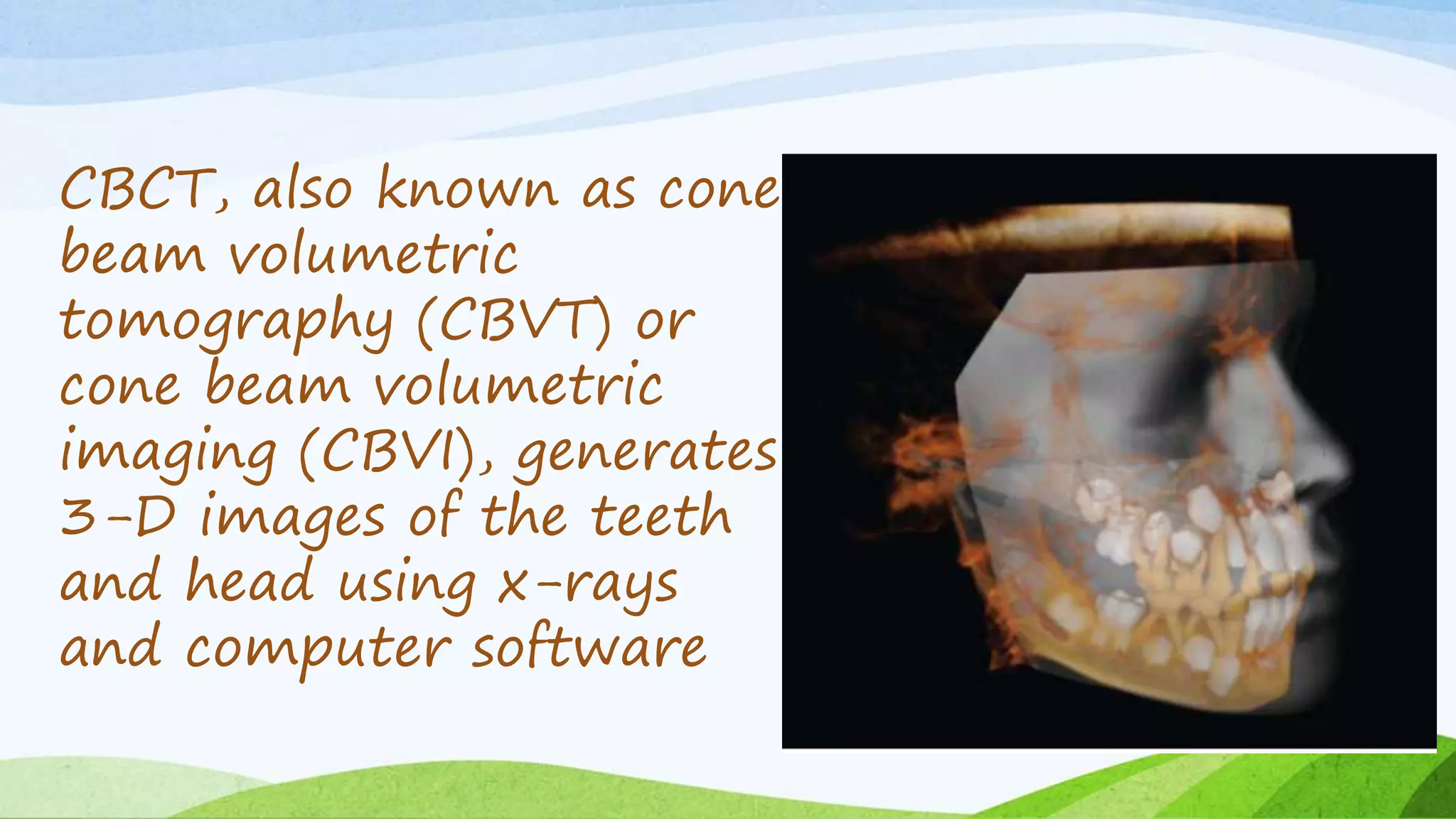
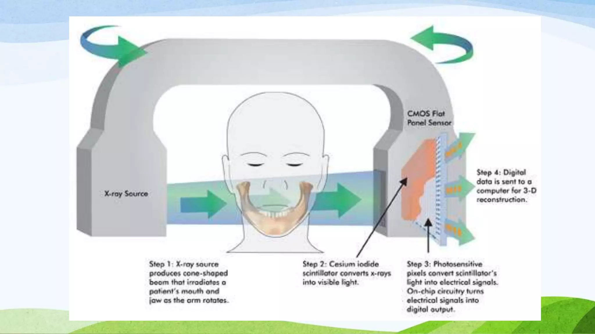
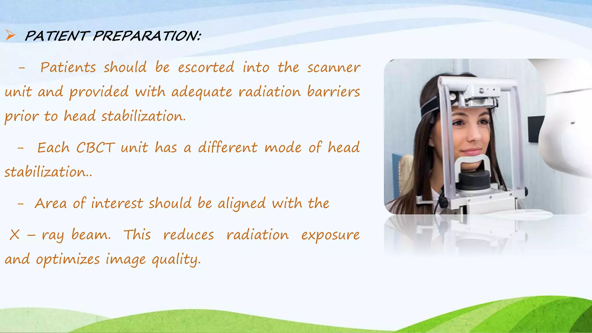
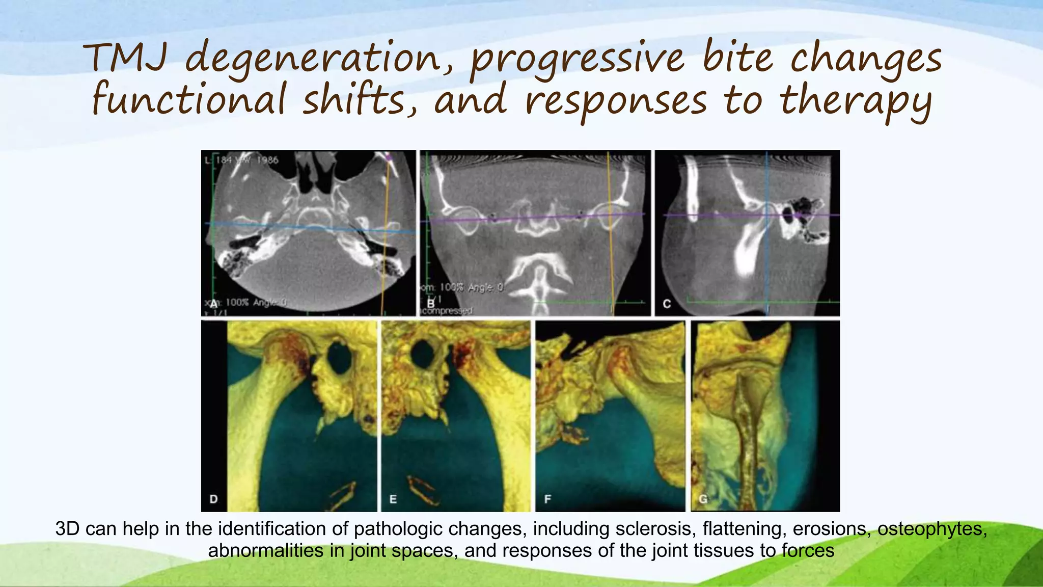
O
O
D
M
O
R
N
I
N
G
WHY 3D?
conventional X-
ray image is
basically a
shadow.
Shadows give you an
incomplete picture of an
object's shape.
CBCT in Orthodontics
Dr Roni R kuttickal
CBCT, also known as cone
beam volumetric
tomography (CBVT) or
cone beam volumetric
imaging (CBVI), generates
3-D images of the teeth
and head using x-rays
and computer software
CONTENTS
• HISTORY
• INTRODUCTION
• CBCT VS CT
• PRINCIPLE
• IMAGE ACQUISITION
• IMAGE DETECTION
• IMAGE RECONSTRUCTION
• IMAGE DISPLAY
• CLINICAL
CONSIDERATIONS
• IMAGE ARTIFACTS
• SPECIFIC APPLICATIONS IN
DENTISTRY
• CONCLUSION
• REFERENCES
CBCT
HISTORY
Sir Godfrey Hounsfield
Introduction
What is cone beam ?
Cone Beam Imaging is fast, simple and
completely painless 3D xray – patients just sit
in a chair for a single 10-second scan. And,
from that scan, the specialist can quickly see
computer-generated views of the bones of the
face, the teeth, and other details from any
angle, in 3D and in color
HOW DOES CT WORK?
1. X-ray source and detector
mounted on a rotating gantry.
2. During rotation, platform will slowly
move & the receptor detects x rays
attenuated by the patient.
3. multiple images will be captured
during rotation.
4. “ raw data ” reconstructed by a
computer algorithm to generate
cross-sectional images.
HOW DOES CBCT WORK?
1)A 3D cone beam is directed through a
central object onto a detector.
2) a single two-dimensional projection is
acquired by the detector,
the x-ray source and detector rotate a
small distance around a trajectory arc.
3) At this second angular position another
basis projection image is captured.
4) This sequence continues around the object
for the entire 360 degrees.
PRINCIPLE
 All CBCT Scanners consist of an x-ray source and
a detector mounted on a rotating gantry.
 During rotation of the gantry, the receptor
detects the x-rays attenuated by the patient.
 These recordings constitute the, “raw data,”
which is then ready for reconstruction.
reconstructed by a computer algorithm
Scanner rotates 360º around
head
Multiple images (150 to
599views)
Software collects raw
data
Image
reconstruction
Cone-beam CT image production
The four components of CBCT image production are
1) Acquisition configuration
• The patient is positioned into the machine with
the head stabilized to avoid movement
• a scout view will be acquired to verify that the
area of interest is within the FOV
• A full scan is done
• 150 to 600 2D images are collected in the
detector.
• Basis images
• detector panels comprise an array of individual
PIXELS with two components,
• 1) Photo diodes - IMAGES
2) Transistors- SIGNALS
• The Data from bad PIXELs are eliminated using an
average
• Details of CBCT imaging is determined by the
individual volume elements or VOXELS produced
from the volumetric dataset.
3) Image reconstruction
• Once the basis projection frames
have been acquired, data must be
processed to create the volumetric
data set called primary
reconstruction.
• The number of individual projection
frames may be from 100 to more
than 600, each with more than one
million pixels, with 12 to 16 bits of
data assigned to each pixel.
A set of 150-600 basis images will be sent to dedicated software
That will then create a 3D volume reconstruction of the data volume
The multiplanar (MPR) reformatted images in axial, coronal, and sagittal orientation
• Acquisition stage
• Reconstruction stage
Image Reconstruction process
Acquisition stage
• The acquisition stage involves image collection
and detector preprocessing ie sequence of the
required calibration steps
Reconstruction stage
• Once images are corrected, they must be related to each other and assembled.
• One method involves constructing a sinogram: a composite image relating each
row of each projection image.
• A reconstruction filter algorithm is applied to the sinogram and converts it into a
complete 2D CT slice.
4) Image display
• unique images demonstrating features in 3D
• Data can be reoriented so that the patient’s anatomic features are
realigned
• Isotropic nature lets images to be sectioned non orthogonally.
Axial
CoronalSagittal
Volumetrc 3-D
PROPERTY
MEDICAL (MULTI – SLICE)
CT
CBCT
COST Expensive Comparatively Cheaper
SOFT TISSUE CONTRAST Better contrast Limited, poor contrast
SCANNING TIME
Lower Speed, requires
multiple rotations
High speed, only one
rotation required.
IMAGE NOISE Lower
Higher
Differences
PROPERTY
MEDICAL (MULTI –
SLICE) CT
CBCT
RADIATION DOSE High Low
IMAGE
RESOLUTION
Low (Hard tissue,
teeth)
High (Hard tissue,
teeth)
METAL ARTIFACT
REDUCTION
Less More
Thus CBCT had a –
1.More rapid acquisition of a data set of the
entire FOV
2.Less expensive radiation detector.
3.A shorter examination time,
4.Shorter time cause Reduction of image
unsharpness
Clinical Analysis
Several steps the clinician must check and analyze for each patient and
clinical situation
Region of interest and field of view: which
anatomical structures are to be visualized
Radiographic Guide: marker showing the exact
location of the desired implant site indicated
Voxel size: Which voxel size would be the best
for this specific situation?
Other: Should the patient’s teeth be in
maximum intercuspal occlusion
 PATIENT PREPARATION:
- Patients should be escorted into the scanner
unit and provided with adequate radiation barriers
prior to head stabilization.
- Each CBCT unit has a different mode of head
stabilization..
- Area of interest should be aligned with the
X – ray beam. This reduces radiation exposure
and optimizes image quality.
- Facial topographical reference planes are
adjusted to align with the x – ray beam.
- Immediately before scanning, the patient should
be asked to remove all metallic objects from the
head and neck areas.
- Patients should be instructed to be as still as
possible and breathe slowly through the nose,
eyes closed.
Patient positioning
• Sitting
• Standing
• Supine
Immobilize patient’s head
- Supine  Occupies a larger surface
- Sitting  Most comfortable, but fixed seats
may not allow scanning of physically disabled
or wheel – chair bound patients.
Erect -Immobilization of the patient’s head
is the most important so that the final
image does not get degraded.
 IMAGING PROTOCOLs - This involves a set of
exposure parameters required for image acquisition.
i.) Voxel Size:  Varies from manufacturer to
manufacturer.
ii.) Scan Time/Number of Projections: increase the
number of basis image projections provides better
reconstruction images, but increases the patient
radiation.
iii.) Scanning Trajectory: Reconstructed images
from limited scan trajectories may suffer from the
presence of artifacts.
iv.) Field of View:
 Collimation enables limitations of the x – ray
beam to the region of interest alone.
 IMAGE REPORTING:
- CBCT imaging not only involves the technical aspect but
interpretation is just as important.
- It includes display of the appropriate region of interest
 ARCHIVING, EXPORT AND DISTRIBUTION:
- The volumetric image data and the generated image report
must be archived and distributed. Export is usually in DICOM
(Digital Imaging and Communications in Medicine)
IMAGE ARTIFACTS
 An artifact is any distortion or error that is
unrelated to the subject being studied.
 This is the fundamental aspect that impairs CBCT
image quality.
ARTIFACT
S
Acquisition
Patient -
Related
Cone – Beam
Related
Scanner -
Related
- Can be corrected by reducing the field of
view, modifying the patient position and by
separating the dental arches.
 PATIENT – RELATED ARTIFACTS:
- Patient motion can cause
misinterpretation of the raw data, which
appears as unsharpness in the
reconstructed image.
- This can be minimized by
restraining the head and using as short a scan
time as possible.
 SCANNER – RELATED ARTIFACTS:
- Usually present as circular or ring
streaks resulting from imperfections in scanner
detection or due to poor calibration.
- ii.) Undersampling:
 This occurs when there are too few
basis images for image reconstruction.
 Leads to sharp edges, misregistration,
and noisier images. It appears as fine striations
in the image.(Aliasing).
Orthodontist related
Classification of CBCT systems
 According to the available FOV or selected scan volume
height CBCT systems can be categorized as
 Localized region: approximately 5 cm or less (eg,
dentoalveolar, temporomandibular joint)
 Single arch: 5 cm to 7 cm (eg, maxilla or mandible)
 Interarch: 7 cm to 10 cm (eg, mandible and superiorly to
include the inferior concha)
 Maxillofacial: 10 cm to 15 cm (eg, mandible and
extending to Nasion)
 Craniofacial: greater than 15 cm (eg, from the lower
border of the mandible to the vertex of the head)
Choice of Field of view
FIND THE SUPERNUMERY
Applications
 IMPLANT SITE ASSESSMENT:
- This has been the greatest impact of CBCT till date.
LOCALIZATION OF THE INFERIOR ALVEOLAR
CANAL:
-
 TEMPOROMANDIBULAR JOINT:
- CBCT provides multiplanar and 3D
images of the condyle and the surrounding structures
to facilitate the analysis and diagnosis of bone
morphologic features, joint space and dynamic
functions.
ML dos Anjos Pontua et al, Evaluation of bone changes in the
temporomandibular joint using cone beam CT, Dentomaxillofacial
Radiology, (2012), 41, 24 - 29
PERIAPICAL
DISEASE
PERIODONTAL
DISEASE
ROOT FRACTURE/ALVEOLAR BONE LOSS
SUPERNUMERARY TEETH
TRITICEOUS CARTILAGE
AND THYROID
CALCIFICATIONS
CAROTID ARTERY AND STYLOID
CALCIFICATIONS
DEMONSTRATION OF FRACTURE
 RAPID PROTOTYPING:
-processes from which physical scale models can
be fabricated directly from 3D computer data
CBCT; In Clinical
Orthodontic Practice
Howcasesarerecordedin
foreignsetups
CBCT offers precise location of impacted
teeth in three dimensions
Cleft Lip and Palate
3D volumetric
reconstructions of a
patient with bilateral
CL/P are useful in
obtaining detailed
information on the
magnitude of the
defect and the status
and position of teeth
at the defect site
Orthognathic and craniofacial anomalies
surgical planning and implementation
Asymmetry
Mirroring on a mid-sagittal plane for quantitation of mandibular asymmetry. A midsagittal
plane was defined for this patient based on Na, Ba, and ANS. The left ramus was
mirrored onto the right side using this plane.
Root resorption
Alveolar boundary conditions
TMJ degeneration, progressive bite changes
functional shifts, and responses to therapy
3D can help in the identification of pathologic changes, including sclerosis, flattening, erosions, osteophytes,
abnormalities in joint spaces, and responses of the joint tissues to forces
Reconstructed pan from a 3-D scan
reconstructed pan can also give a much better view of root alignment
Reconstructed ceph from a 3-D scan
ROOT ANGULATION
Sinus And Airway Airway assessment
Measuring bone dimensions for miniimplant
placement
LOST TADS
Assessment Rapid maxillary expansion
CAD planning software for orthodontics
Everythingcomeswitha
price
CONCLUSION
The introduction of CBCT imaging systems have provide a better
environment for the clinician in terms of providing accurate, submillimeter
resolution images at lower doses, costs and scanning time, when compared to
CT. The availability of this technology is increasing day by day and its capability
in providing the practitioner with a 3D representation has changed the face of
dentistry over the years. Maxillofacial imaging has shifted gears from the art of
diagnosis to the guidance of operative and surgical procedures, thanks to CBCT.
References
1)WHAT IS CONE-BEAM CT AND HOW DOES IT WORK? WILLIAM C. SCARFE, BDS,
FRACDS, MSA,*, ALLAN G. FARMAN, BDS, PHD, DSC, MBAB
2)CBCT; IN CLINICAL ORTHODONTIC PRACTICE
PROF. DR. NEZAR WATTED*, PROF. DR. DR.PETER PROFF ,**DR. VADIM REISER***, DR.
BENJAMIN SHLOMI***, DR. MUHAMAD ABU-HUSSEIN****,DR.DROR SHAMIR*****
3)CLINICAL RECOMMENDATIONS REGARDING USE OF CONE BEAM COMPUTED
TOMOGRAPHY IN ORTHODONTICS. POSITION STATEMENT BY THE AMERICAN ACADEMY
OF ORAL AND MAXILLOFACIAL RADIOLOGY -AMERICAN ACADEMY OF ORAL AND
MAXILLOFACIAL RADIOLOGY
4)USING CONE BEAM TECHNOLOGY IN ORTHODONTICS-EDWARD LIN
5)THE USE OF CBCT IN ORTHODONTICS: RECOMMENDATIONS FOR CLINICAL PRACTICE
-ALBERTO CAPRIOGLIO
6)CBCT – AN ADVANCED DIAGNOSTIC TOOL FOR ORTHODONTICS AND OTHER
SPECIALTIES IN DENTISTRY – A SYSTEMATIC REVIEW- A VISHVANATH
7)CBCT IN ORTHODONTICS: THE WAVE OF FUTURE - JCDP
THANK YOU
CBCT IN ORTHODONTICS

CBCT IN ORTHODONTICS

  • 1.
  • 5.
  • 6.
    conventional X- ray imageis basically a shadow. Shadows give you an incomplete picture of an object's shape.
  • 7.
    CBCT in Orthodontics DrRoni R kuttickal
  • 8.
    CBCT, also knownas cone beam volumetric tomography (CBVT) or cone beam volumetric imaging (CBVI), generates 3-D images of the teeth and head using x-rays and computer software
  • 9.
    CONTENTS • HISTORY • INTRODUCTION •CBCT VS CT • PRINCIPLE • IMAGE ACQUISITION • IMAGE DETECTION • IMAGE RECONSTRUCTION • IMAGE DISPLAY • CLINICAL CONSIDERATIONS • IMAGE ARTIFACTS • SPECIFIC APPLICATIONS IN DENTISTRY • CONCLUSION • REFERENCES
  • 10.
  • 11.
  • 15.
  • 16.
    What is conebeam ? Cone Beam Imaging is fast, simple and completely painless 3D xray – patients just sit in a chair for a single 10-second scan. And, from that scan, the specialist can quickly see computer-generated views of the bones of the face, the teeth, and other details from any angle, in 3D and in color
  • 18.
    HOW DOES CTWORK? 1. X-ray source and detector mounted on a rotating gantry. 2. During rotation, platform will slowly move & the receptor detects x rays attenuated by the patient. 3. multiple images will be captured during rotation. 4. “ raw data ” reconstructed by a computer algorithm to generate cross-sectional images.
  • 19.
    HOW DOES CBCTWORK? 1)A 3D cone beam is directed through a central object onto a detector. 2) a single two-dimensional projection is acquired by the detector, the x-ray source and detector rotate a small distance around a trajectory arc. 3) At this second angular position another basis projection image is captured. 4) This sequence continues around the object for the entire 360 degrees.
  • 22.
    PRINCIPLE  All CBCTScanners consist of an x-ray source and a detector mounted on a rotating gantry.  During rotation of the gantry, the receptor detects the x-rays attenuated by the patient.  These recordings constitute the, “raw data,” which is then ready for reconstruction. reconstructed by a computer algorithm
  • 23.
    Scanner rotates 360ºaround head Multiple images (150 to 599views) Software collects raw data Image reconstruction
  • 24.
    Cone-beam CT imageproduction The four components of CBCT image production are
  • 25.
    1) Acquisition configuration •The patient is positioned into the machine with the head stabilized to avoid movement • a scout view will be acquired to verify that the area of interest is within the FOV • A full scan is done • 150 to 600 2D images are collected in the detector. • Basis images
  • 26.
    • detector panelscomprise an array of individual PIXELS with two components, • 1) Photo diodes - IMAGES 2) Transistors- SIGNALS • The Data from bad PIXELs are eliminated using an average • Details of CBCT imaging is determined by the individual volume elements or VOXELS produced from the volumetric dataset.
  • 28.
    3) Image reconstruction •Once the basis projection frames have been acquired, data must be processed to create the volumetric data set called primary reconstruction. • The number of individual projection frames may be from 100 to more than 600, each with more than one million pixels, with 12 to 16 bits of data assigned to each pixel.
  • 29.
    A set of150-600 basis images will be sent to dedicated software That will then create a 3D volume reconstruction of the data volume The multiplanar (MPR) reformatted images in axial, coronal, and sagittal orientation
  • 30.
    • Acquisition stage •Reconstruction stage Image Reconstruction process
  • 31.
    Acquisition stage • Theacquisition stage involves image collection and detector preprocessing ie sequence of the required calibration steps
  • 32.
    Reconstruction stage • Onceimages are corrected, they must be related to each other and assembled. • One method involves constructing a sinogram: a composite image relating each row of each projection image. • A reconstruction filter algorithm is applied to the sinogram and converts it into a complete 2D CT slice.
  • 34.
    4) Image display •unique images demonstrating features in 3D • Data can be reoriented so that the patient’s anatomic features are realigned • Isotropic nature lets images to be sectioned non orthogonally.
  • 35.
  • 36.
    PROPERTY MEDICAL (MULTI –SLICE) CT CBCT COST Expensive Comparatively Cheaper SOFT TISSUE CONTRAST Better contrast Limited, poor contrast SCANNING TIME Lower Speed, requires multiple rotations High speed, only one rotation required. IMAGE NOISE Lower Higher Differences
  • 37.
    PROPERTY MEDICAL (MULTI – SLICE)CT CBCT RADIATION DOSE High Low IMAGE RESOLUTION Low (Hard tissue, teeth) High (Hard tissue, teeth) METAL ARTIFACT REDUCTION Less More
  • 38.
    Thus CBCT hada – 1.More rapid acquisition of a data set of the entire FOV 2.Less expensive radiation detector. 3.A shorter examination time, 4.Shorter time cause Reduction of image unsharpness
  • 40.
    Clinical Analysis Several stepsthe clinician must check and analyze for each patient and clinical situation Region of interest and field of view: which anatomical structures are to be visualized Radiographic Guide: marker showing the exact location of the desired implant site indicated Voxel size: Which voxel size would be the best for this specific situation? Other: Should the patient’s teeth be in maximum intercuspal occlusion
  • 41.
     PATIENT PREPARATION: -Patients should be escorted into the scanner unit and provided with adequate radiation barriers prior to head stabilization. - Each CBCT unit has a different mode of head stabilization.. - Area of interest should be aligned with the X – ray beam. This reduces radiation exposure and optimizes image quality.
  • 42.
    - Facial topographicalreference planes are adjusted to align with the x – ray beam. - Immediately before scanning, the patient should be asked to remove all metallic objects from the head and neck areas. - Patients should be instructed to be as still as possible and breathe slowly through the nose, eyes closed.
  • 43.
    Patient positioning • Sitting •Standing • Supine Immobilize patient’s head
  • 44.
    - Supine Occupies a larger surface
  • 45.
    - Sitting Most comfortable, but fixed seats may not allow scanning of physically disabled or wheel – chair bound patients.
  • 46.
    Erect -Immobilization ofthe patient’s head is the most important so that the final image does not get degraded.
  • 47.
     IMAGING PROTOCOLs- This involves a set of exposure parameters required for image acquisition. i.) Voxel Size:  Varies from manufacturer to manufacturer. ii.) Scan Time/Number of Projections: increase the number of basis image projections provides better reconstruction images, but increases the patient radiation. iii.) Scanning Trajectory: Reconstructed images from limited scan trajectories may suffer from the presence of artifacts.
  • 48.
    iv.) Field ofView:  Collimation enables limitations of the x – ray beam to the region of interest alone.
  • 49.
     IMAGE REPORTING: -CBCT imaging not only involves the technical aspect but interpretation is just as important. - It includes display of the appropriate region of interest  ARCHIVING, EXPORT AND DISTRIBUTION: - The volumetric image data and the generated image report must be archived and distributed. Export is usually in DICOM (Digital Imaging and Communications in Medicine)
  • 50.
    IMAGE ARTIFACTS  Anartifact is any distortion or error that is unrelated to the subject being studied.  This is the fundamental aspect that impairs CBCT image quality. ARTIFACT S Acquisition Patient - Related Cone – Beam Related Scanner - Related
  • 51.
    - Can becorrected by reducing the field of view, modifying the patient position and by separating the dental arches.
  • 52.
     PATIENT –RELATED ARTIFACTS: - Patient motion can cause misinterpretation of the raw data, which appears as unsharpness in the reconstructed image. - This can be minimized by restraining the head and using as short a scan time as possible.
  • 53.
     SCANNER –RELATED ARTIFACTS: - Usually present as circular or ring streaks resulting from imperfections in scanner detection or due to poor calibration.
  • 54.
    - ii.) Undersampling: This occurs when there are too few basis images for image reconstruction.  Leads to sharp edges, misregistration, and noisier images. It appears as fine striations in the image.(Aliasing).
  • 55.
  • 56.
    Classification of CBCTsystems  According to the available FOV or selected scan volume height CBCT systems can be categorized as  Localized region: approximately 5 cm or less (eg, dentoalveolar, temporomandibular joint)  Single arch: 5 cm to 7 cm (eg, maxilla or mandible)  Interarch: 7 cm to 10 cm (eg, mandible and superiorly to include the inferior concha)  Maxillofacial: 10 cm to 15 cm (eg, mandible and extending to Nasion)  Craniofacial: greater than 15 cm (eg, from the lower border of the mandible to the vertex of the head)
  • 58.
  • 59.
  • 61.
  • 63.
     IMPLANT SITEASSESSMENT: - This has been the greatest impact of CBCT till date.
  • 64.
    LOCALIZATION OF THEINFERIOR ALVEOLAR CANAL: -
  • 65.
     TEMPOROMANDIBULAR JOINT: -CBCT provides multiplanar and 3D images of the condyle and the surrounding structures to facilitate the analysis and diagnosis of bone morphologic features, joint space and dynamic functions. ML dos Anjos Pontua et al, Evaluation of bone changes in the temporomandibular joint using cone beam CT, Dentomaxillofacial Radiology, (2012), 41, 24 - 29
  • 66.
  • 67.
    ROOT FRACTURE/ALVEOLAR BONELOSS SUPERNUMERARY TEETH
  • 68.
  • 69.
  • 70.
     RAPID PROTOTYPING: -processesfrom which physical scale models can be fabricated directly from 3D computer data
  • 71.
  • 72.
  • 76.
    CBCT offers preciselocation of impacted teeth in three dimensions
  • 77.
    Cleft Lip andPalate 3D volumetric reconstructions of a patient with bilateral CL/P are useful in obtaining detailed information on the magnitude of the defect and the status and position of teeth at the defect site
  • 78.
    Orthognathic and craniofacialanomalies surgical planning and implementation
  • 79.
    Asymmetry Mirroring on amid-sagittal plane for quantitation of mandibular asymmetry. A midsagittal plane was defined for this patient based on Na, Ba, and ANS. The left ramus was mirrored onto the right side using this plane.
  • 80.
  • 81.
  • 82.
    TMJ degeneration, progressivebite changes functional shifts, and responses to therapy 3D can help in the identification of pathologic changes, including sclerosis, flattening, erosions, osteophytes, abnormalities in joint spaces, and responses of the joint tissues to forces
  • 83.
    Reconstructed pan froma 3-D scan reconstructed pan can also give a much better view of root alignment
  • 84.
  • 85.
  • 86.
    Sinus And AirwayAirway assessment
  • 89.
    Measuring bone dimensionsfor miniimplant placement
  • 90.
  • 91.
  • 92.
    CAD planning softwarefor orthodontics
  • 93.
  • 95.
    CONCLUSION The introduction ofCBCT imaging systems have provide a better environment for the clinician in terms of providing accurate, submillimeter resolution images at lower doses, costs and scanning time, when compared to CT. The availability of this technology is increasing day by day and its capability in providing the practitioner with a 3D representation has changed the face of dentistry over the years. Maxillofacial imaging has shifted gears from the art of diagnosis to the guidance of operative and surgical procedures, thanks to CBCT.
  • 96.
    References 1)WHAT IS CONE-BEAMCT AND HOW DOES IT WORK? WILLIAM C. SCARFE, BDS, FRACDS, MSA,*, ALLAN G. FARMAN, BDS, PHD, DSC, MBAB 2)CBCT; IN CLINICAL ORTHODONTIC PRACTICE PROF. DR. NEZAR WATTED*, PROF. DR. DR.PETER PROFF ,**DR. VADIM REISER***, DR. BENJAMIN SHLOMI***, DR. MUHAMAD ABU-HUSSEIN****,DR.DROR SHAMIR***** 3)CLINICAL RECOMMENDATIONS REGARDING USE OF CONE BEAM COMPUTED TOMOGRAPHY IN ORTHODONTICS. POSITION STATEMENT BY THE AMERICAN ACADEMY OF ORAL AND MAXILLOFACIAL RADIOLOGY -AMERICAN ACADEMY OF ORAL AND MAXILLOFACIAL RADIOLOGY 4)USING CONE BEAM TECHNOLOGY IN ORTHODONTICS-EDWARD LIN 5)THE USE OF CBCT IN ORTHODONTICS: RECOMMENDATIONS FOR CLINICAL PRACTICE -ALBERTO CAPRIOGLIO 6)CBCT – AN ADVANCED DIAGNOSTIC TOOL FOR ORTHODONTICS AND OTHER SPECIALTIES IN DENTISTRY – A SYSTEMATIC REVIEW- A VISHVANATH 7)CBCT IN ORTHODONTICS: THE WAVE OF FUTURE - JCDP
  • 97.

Editor's Notes

  • #3 The chain of events that lead to my seminar started with this after this man Wilhelm Conrad Roentgen in 1895 ,found that the bones of his hand clearly were displayed in an outline of flesh when he held it between a cathode ray tube and a barium-coated screen.
  • #4 EVER SENSE xray technolog HAD A PHENOMENAL AGROWTH we indroduced techniques which reduced radiation doses to patients like faster films . This development was furthered by the introduction of digital radiography like rvg then came psp which was more comfortable - radiation doses generally are lower than with conventional dental radiographs. They offer quicker image taking and accuracy, the ability to store the images indefinitely in computer archives without deterioration, and the ability to send them to other clinicians as a digital file when required.
  • #5 Our strive for excellence didn’t let us settle for jus 2d images CERN Colourised xray based on European nuclear research centre
  • #6 We DIDN’T SETTLE FOR 2D IMAGES
  • #7 This is the basic idea of computer aided tomography. In a CT scan machine, the X-ray beam moves all around the person, scanning from hundreds of different angles.
  • #8 From the early days of dental radiographs, the concepts did not change significantly until 3-dimensional imaging was introduced.
  • #9 Cone Beam Computed Tomography (CBCT) is a recent technology developed for angiography in 1982, then was later applied to maxillofacial imaging.
  • #11 From the early days of dental radiographs, the concepts did not change significantly until 3-dimensional imaging was introduced.
  • #12 1972: Sir Godfrey Hounsfield won the Nobel Prize for the developent of x – ray Computed Tomography in 1979 Passed away in 2004
  • #13 Each slice is placed back together to form 3d image
  • #14 1982: The first introduction of Cone Beam Computed Tomography (CBCT). It was primarily used for angiography. Took 6mins to rotate and 30 mins to reconstruct
  • #15  Tacconi, Mozzo, Godi and Ronca made First images made using Cone beam technology was first introduced in the European market in 1996 by QR s.r.l. (NewTom 9000) 2002: Limited volume CBCT prototype first introduced in Europe, derived from J. Morita. It was known as 3D Accuitomo. The newer version was developed in 2005.
  • #17 Intraoral and extraoral 2d procedures, used individually or in combination, suffer from the same inherent limitations of all planar two-dimensional (2D) projections: magnification, distortion, superimposition, and misrepresentation of structures.
  • #18 CT, uses a fan-shaped x-ray beam in a helical progression to acquire individual image slices of the FOV and then stacks the slices to obtain a 3D representation. Each slice requires a separate scan and separate 2D reconstruction. Because CBCT exposure incorporates the entire FOV, only one rotational sequence of the gantry is necessary to acquire enough data for image reconstruction Only since the late 1990’s was it possible to produce systems which are both inexpensive and small enough to be used in the dental office.
  • #20 1)A 3D cone beam is directed through a central object onto a detector. 2) After a single two-dimensional projection is acquired by the detector, the x-ray source and detector rotate a small distance around a trajectory arc. 3) At this second angular position another basis projection image is captured. 4) This sequence continues around the object for the entire 360 degrees
  • #21 X-ray beam projection scheme comparing acquisition geometry of conventional or ‘‘fan’’ beam (right) and ‘‘cone’’ beam (left) imaging geometry and resultant image production. In cone-beam geometry (left), multiple basis projections form the projection data from which orthogonal planar images are secondarily reconstructed. In fan beam geometry, primary reconstruction of data produces axial slices from which secondary reconstruction generates orthogonal images. The amount of scatter generated (sinusoidal lines) and recorded by cone-beam image acquisition is substantially higher, reducing image contrast and increasing image noise
  • #22 . In a CBCT machine, an x-ray source and a sensor are placed 180° apart on a rotating arm, and the patient is placed in the middle (Figure 1). CBCT uses a cone-shaped x-ray beam to acquire a volume of data at each frame, generating a complete 3-D image (Figure 2) in one rotation or less. It requires a much lower dose of radiation than medical computed tomography (CT), a benefit to patients.
  • #24  The options for the thickness of the layers to be reconstructed are 0.3 mm, 1.0 mm, and 3.0 mm,
  • #26 The geometric configuration and acquisition mechanics for the conebeam technique are theoretically simple. A single partial or full rotational scan from an x-ray source takes place while a reciprocating area detector moves synchronously with the scan around a fixed fulcrum within the patient’s head. these 2D images are called. The exact number of basis images will be determined by the degree of rotation and the time of acquisition. A faster scan will acquire fewer images, whereas a longer scan will acquire more basis images and thus more information will be provided and a better quality image will be created.
  • #27 an image intensifier tube/charge-coupled device (IIT/CCD) With flat panal having better dynamic range and greater performance photodiodes that actually record the image and thin-film transistors that act as collators and carriers of signal information. Bad pixels are also examined and most often replaced by the average of the neighboring pixels.er.
  • #28 2D images are made of several pixels (represented as squares, with height and width) and the smaller the pixel the better the quality of the picture the same concept applies to a 3D data volume. Each three-dimensional voxel represents a specific x-ray absorption. A voxel is the smallest 3D element of the volume, The voxel size on CBCT images is isotropic Digital imaging and communication in medicine
  • #29 IMAGES GETS ARRANGED IN A 3D GRID
  • #30 The coronal images look at the patient from behind in a series of images starting at the back of the head and moving towards the face (anteroposterior view). The sagittal plane will allow evaluation of the patient’s structures from side-to-side in a series of images starting at one ear and moving to the other. The axial plane evaluates the patient from below in a series of images starting at the chin and moving to the top of the head (axial view)
  • #31 Again consists of In contrast to conventional CT, cone-beam data reconstruction is performed by personal computer rather than workstation platforms
  • #32 PUTTING TOGETHER OF THE IMAGE OR PRIMARY RECONSTRUCTION IS DONE
  • #33 A reconstruction filter algorithm is applied to the sinogram and converts it into a complete 2D CT slice.
  • #34 Feldkamp LA, Davis LC, Kress JW. Practical cone-beam algorithm. J Opt Soc Am 1984; A1(6):612–9. Feldkamp, L. A.; Davis, L. C.; Kress, J. W.
  • #35 Multi planar reformation that intraoral, panoramic,and cephalometric images cannot are displayed
  • #36 The coronal images look at the patient from behind in a series of images starting at the back of the head and moving towards the face (anteroposterior view). The sagittal plane will allow evaluation of the patient’s structures from side-to-side in a series of images starting at one ear and moving to the other. The axial plane evaluates the patient from below in a series of images starting at the chin and moving to the top of the head (axial view)
  • #37 Ie if the ct machine will cost 1 crore and cbct from 54 to 75 lacks
  • #40 TOO SUMMERISE
  • #41 European union radiation guide lines gives 20 sets of criterias under which cbct can be taken, CBCT examinations must not be carried out unless a history and clinical examination have been performed ,2 CBCT examinations must be justified for each patient to demonstrate that the benefits outweigh the risks 3CBCT examinations should potentially add new information to aid the patient’s management 4 CBCT should not be repeated ‘routinely’ on a patient without a new risk/benefit assessment having been performed Which teeth or anatomical structures are to be visualized? Are the TMJ areas to be included in the scan? Is visualization of both dental arches required, or only one arch? Is partial visualization of the maxillary sinuses enough? Is a radiographic marker showing the exact location of the desired implant site indicated? Will guided surgery be required? Is the radiographic guide well-adapted? In the cases where the scan will be acquired at a separate location and a radiographic guide will be used, the referring clinician must pre-fit and assess the guide prior to the scan appointment. Also, the clinician should explain to the patient the correct position of the radiographic guide to avoid malposition.
  • #46 Least distortion of image
  • #49 Decrease in voxel size increases the spatial resolution, but a higher radiation dose may be required.
  • #53 Artifacts
  • #59 CBCT provides an equivalent patient radiation dose of 5 to 74 times that of a single film-based panoramic X ray, or 3 to 48 days of background radiation
  • #62 The choice of the FOV is based on the diagnostic objectives for the imaging as determined through a careful clinical assessment of the patient. The recommended FOV for specific needs also is dependent on the size of the individual. Thus, if the image of the entire craniofacial region is needed, it might entail using a large FOV for a child and an extended FOV for an adult.
  • #63 Lets take a break Mixed dentition
  • #64 Cbct image
  • #67 Provides cross – sectional images of the alveolar bone height, width, and angulation. Accurately depicts the presence of vital structures like the Inferior Alveolar Canal and Maxillary Sinus.
  • #68 The relationship of the canal to the roots of the mandibular teeth is important when treatment involves minimizing the likelihood of nerve damage. traditional panoramic imaging may be useful if the tooth is clear from the canal, but in the event of superimposition, 3D imaging gives a clearer picture.
  • #72 The triticeal cartilage (TC) is a small oval-shaped cartilage found within the lateral border of the thyrohyoid membrane between the greater horn of the hyoid bone and the superior horn of the thyroid cartilage
  • #74 It is a broad term used to describe a group of processes from which physical scale models can be fabricated directly from 3D computer data. - A life size, dimensionally accurate model of various anatomical structures can be created. (Biomodels). - They are useful in pre – surgical treatment planning of various maxillofacial surgical cases.
  • #80 Depiction of impacted maxillary canines using a conventional 2D panorex (A) and 3D volumetric rendering. The 3D images permit clear visualization of the location and relationships of the impacted canines to adjacent structures, as well as the presence of any root resorption. it facilitates treatment decisions, including determination of teeth to be extracted.if yes then the optimal surgical approach, appropriate placement of attachments, and biomechanics planning.
  • #81 1) valuable in determining the volume of the alveolar defect and, therefore, the amount of bone needed for grafting in CL/P patients 2) for determining the success of bone fill following surgery (Oberoi et al ., 2009;Shirota et al ., 2010) 3) numbers, quality, and location of teeth in proximity to the cleft site (Zhou et al ., 2013), 4) The eruption status and path of canines in grafted cleft sites (Oberoi et al ., 2010)
  • #82 CBCT combined with computer-aided surgical simulation (CASS) or computer-aided Orthognathic surgery (CAOS) offers 2) refining diagnosis and optimizing treatment objectives in 3D 4) virtual treatment planning to improve surgical procedures and outcomes. Virtual surgical treatment planning for a patient to visualize and determine the magnitude of maxillary and mandibular movements, as well as any complication such as proximal segment interferences that may arise during surgery.
  • #83 3D CBCT imaging in the diagnosis and treatment planning of asymmetries, where discrepancies often manifest in all three planes of space. 1) When large differences exist between bilateral structures, CBCT scans enable the use of a technique called “mirroring” 2) In which the normal side is mirrored onto the discrepant side so as to simulate and visualize the desired end result, as well as to plan the surgery to facilitate correction (Metzger et al ., 2007) Limitation of mirroring  Mirroring using mid-sagittal plane generates inaccurate and clinically irrelevant results for patients 1.cleft palate with facial features that affect the midline position of the points (NA, ANS, Ba) used to define this plane. 2.in patients with asymmetries involving the cranial base, registration on the cranial base also results in suboptimal results.  This implies that patient specific methods may be indicated for optimal localization and quantification of mandibular asymmetries.
  • #84 Root resorption  Detection of buccal or lingual root resorption by CBCT that is not visualized by 2D radiographs could differentiate pre- or in-treatment decisions made with the two imaging modalities.  So the dilemma, in this scenario is how and when a clinician would decide that a patient has undergone buccal and/or lingual root resorption to justify taking CBCT scan.
  • #85 Compromised pretreatment alveolar boundary conditions may limit or interfere with the planned or potential tooth movement, as well as the final desired spatial position and angulation of the teeth. Failure to diagnose compromised alveolar bone prior to treatment and to involve this into the treatment plan likely will lead to worsening of the problem during orthodontic treatment. Determination of anterior boundary conditions in a case with severely retroclined maxillary and mandibular incisors using sagittal (A), axial (B) and coronal (C) multiplanar, and 3D volumetric (Dand E) reconstructions.a severe Class II division 2 malocclusion presents with upper incisor roots that have limited buccal bone support that could be placed into a better relationship with the bone through lingual root torque.
  • #86 Conventional 2D radiography of the TMJ including panoramic radiographs and cephalograms do not provide an accurate characterization of the joint because of distorted images with superimposed structures. CBCT imaging of entire joint spaces with visualization of osseous hard tissue morphologic changes resulting from pathology and adaptive processes allows for accurate detection and evaluation of pathological changes.
  • #87 While there is a need for 2-D panoramics in the orthodontic practice, for many orthodontists, a 3-D machine (which also serves as a traditional 2-D digital panoramic) is the best of both worlds. It has the added benefit of being able to reconstruct the 3-D scan data into a panoramic (along with other typical orthodontic views), thereby giving the clinician numerous radiographic options in one system
  • #88 Dr David Hatcher, a dental radiologist, has noted that both a panoramic and a cephalogram can be reconstructed through cone beam data, but with even better quality and with the added benefit of a view of the joint in the fossa with the teeth in occlusion all at once With the conventional cephalometric techniques, complex 3D structures are projected onto a 2D plane. Consequently there are restrictions including superimposition of anatomical structures CBCT allows the 3D visualization of the craniofacial skeleton, so accurate evaluation of the anatomic structures it’s achievable. Crosssectional slices in all 3 views of space take full advantage of the 3D CBCT information. Moreover, from the evaluation of landmarks, lines, distances and angles CBCT allows the assessment of surfaces, areas and volume. In general, CBCT is very useful for selected orthodontic and surgical patients. The CBCT data set can be reformatted to generate a CBCTreconstructed lateral cephalogram so that conventional measurements can be made and compared with existing 2D norms. These CBCT reconstructed lateral cephalograms (Fig. 4) offer the advantage of ability to digitally reorient the head position in cases in which the patient did not undergo scanning with the proper head position.
  • #89 PAN – positions root of posterior maxilla more distallall and anteriors mesially and in lower arch all roots are mesially positioned
  • #90 The normal airway has been described as oval shaped with a larger lateral distance compared with the anterior posterior distance. CBCT technology provides a major improvement for evaluation of the airway, allowing for 3dimensional and volumetric analysis. Airway analysis conventionally has been carried out by using lateral cephalograms. Three dimensional airway analysis will be useful for the understanding of more complex conditions such as obstructive sleep apnea (OSA) and enlarged adenoids. Volumetric data obtained from a CBCT survey can be used to visualize the sinuses and the entire airway path from the nasal and oral entrances to the laryngeal spaces for: Identification of anatomical borders Determination of degree of infection and presence of polyps Assistance in airway studies for diagnosis and treatment of obstructive sleep apnea Calculation of actual volume of airway space Determination of the point of airway constriction
  • #91 Volumetric data obtained from a CBCT survey can be used to visualize the sinuses and the entire airway path from the nasal and oral entrances to the laryngeal spaces for: Identification of anatomical borders Determination of degree of infection and presence of polyps Assistance in airway studies for diagnosis and treatment of obstructive sleep apnea Calculation of actual volume of airway space Determination of the point of airway constriction
  • #92 The lateral cephalogram has a high sensitivity and high negative predictive value, therefore, an additional complementary examination would not be necessary if the 2D assessment of the upper airway throws a normal result. It is suggested that when the upper airway is decreased in the lateral cephalogram, it would be appropriate to perform CBCT to confirm.
  • #93 The miniimplants have been widely used in orthodontic practice as temporary anchorage devices. Their diameter is ≈ 1.8 mm. They can be either immediate or delayed loading. They can be positioned in many areas of the alveolar bone. It is crucial to identify the ideal site for insertion of the miniimplants. Particularly, to insure that the placement of miniimplants will be safe and won’t cause damage to anatomical structures or teeth. Consequently, the cortical bone thickness and bone pattern are important criteria in miniimplant selection and factors that affect their stability.
  • #95 radiographs such as overlapping of structures leading to landmark identification errors and measurement errors obstruct the assessment of the skeletal and dental changes The CBCT scanning technology overcomes these obstacles and provides superior reliability and greater accuracy in the evaluation of bone changes.
  • #96 Insignia™ Advantage For instance, highly sophisticated software and CAD applications are now available to create a 3-D computer model of the bite by using advanced imaging technology, The scan offers full anatomical details so that orthodontists can see the roots and the crowns of the teeth (Figure 10), not just the crowns, resulting in more accurate robotic archwire setups.
  • #97 Roentgen equivalent man is measure of the relative harm or risk caused by a given dose of radiation simply, the rem can be thought of as the unit of biological hazard. 1 rem = 1000 millirem One sievert equals 100 rem So while taking I cbct 135 micro Sievert is fired that is 0.135 mille Sievert If max dose in a pregnant women is 5 msv per term the – 5/0.135= 37 cbct x rays can be taken without damage to fetus