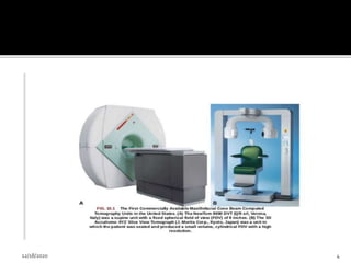
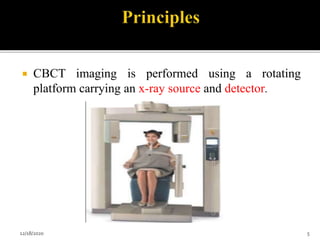
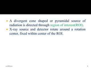
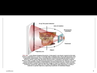
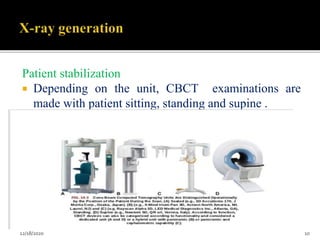
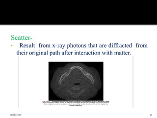
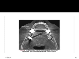
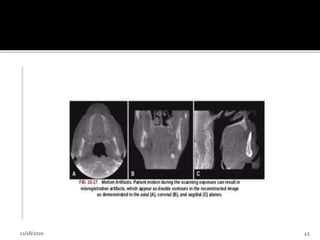
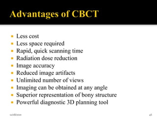
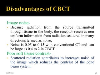
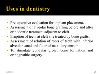
12/18/2020 1
 Introduction
 Principles
 Image Acquisition
X-ray generation
Image detection system
Image reconstruction
Image display
 Clinical consideration
 Imaging protocol
 Comparison with CT
 Artifacts
 Applications in Dentistry
12/18/2020 2
 It is also known as Dental computed tomography,
Cone beam volumetric tomography, Volumetric
computed tomography or Cone beam imaging.
 A recent technology initially developed for
angiography in 1982.
 It uses cone shaped beam of X-ray photons which
can scan the region of interest in a single 360⁰
rotation.
 Most significant technology advancement in
maxillofacial imaging.
12/18/2020 3
12/18/2020 4
 CBCT imaging is performed using a rotating
platform carrying an x-ray source and detector.
12/18/2020 5
 A divergent cone shaped or pyramidal source of
radiation is directed through region of interest(ROI).
 X-ray source and detector rotate around a rotation
center, fixed within center of the ROI.
12/18/2020 6
 During rotation, multiple sequential planer projection
images are obtained while the x-ray source and
detector move through an arc of 180 to 360 degree.
 Single projection image from raw primary data,
which is individually known as basis frame or raw
image.
 Usually several hundred 2- D basic images from
which the image volume is calculated.
 Complete series of images is called Projection data.
12/18/2020 7
12/18/2020 8
 X-ray generation
 X-ray detection
 Image reconstruction
12/18/2020 9
Patient stabilization
 Depending on the unit, CBCT examinations are
made with patient sitting, standing and supine .
12/18/2020 10
 With all system, immobilization of the
patients head is more important than position
because any movement degrades the final
image.
 Immobilization of head by-
1. Chin cup
2. Bite fork
3. Other head-restraint mechanism
12/18/2020 11
12/18/2020 12
X-ray generator
X-ray generation
continuous or pulsed
 When pulsed- exposure time is upto 50% less than
scanning time(this technique reduces patients
radiation dose)
 ALARA (As Low As Reasonable Achievable)
principle dose optimization states that CBCT
exposure factor should be adjusted on the basis of
patients size.
12/18/2020 13
Scan volume /field of view(FOV)
 Detector size
 Shape
 Beam projection geometry
 Ability to collimate the beam
12/18/2020 14
 It is desirable to limit the field size to the smallest
volume that images the ROI.
 This procedure reduces unnecessary exposure to the
patient and produces the best image by minimum
scattered radiation, which degrade the image quality.
12/18/2020 15
12/18/2020 16
12/18/2020 17
12/18/2020 18
Scan factor
 Number of images forming the “projection data”
throughout the scan is determined by-
1. Detector frame rate(no. of image acquired per
second).
2. Completeness of the trajectory arc (180 to 360)
3. Rotation speed of source and detector
12/18/2020 19
 Divided into two groups based on detector type:
1. Image intensifier tube/charge- coupled device
 Larger and bulkier and result in circular basis image area
spherical volume
2. Flat panel detector (FPDs)
 Lighter in weight ,rectangular cylindrical volume, consists of
cesium iodide scintillator applied to a thin film transistor
made of amorphous silicon.
12/18/2020 20
Voxel- Volume element
 Individual volume element is voxel.
 Voxels form the volumetric data set.
 CBCT units provide voxel resolution that are
isotropic-equal in all 3 dimension.
 Determinant of voxel is- Pixel size of detector
detector with small pixel
Capture few x-ray photon per voxel
12/18/2020 21
Basis projection frames
Volumetric data
a single CBCT rotation take less than 20 sec
Produce 100 to 600 individual projection frames
Each with more than 1 million pixel with 12 to 16 bits of
data assigned to each pixel
These data processed to create volumetric data set(voxel)
by a sequence of software algorithms a process known as
Reconstruction
12/18/2020 22
12/18/2020 23
1.Preprocessing stage
 Performed at acquisition computer.
 Inherent pixel imperfections should be corrected.
 Exposure normalization.
2. Reconstruction stage
 Corrected images are converted into a special
representation called a sinogram.
 Sinogram is a composite image developed from
multiple projection images.
12/18/2020 24
1.Patient selection criteria
• It provides a radiation dose higher than other
dental radiographic procedures.
• Panoramic and periapical view cannot
provide necessary information for patient
diagnosis and treatment.
• Used as adjunctive diagnostic tool.
12/18/2020 25
2. Patient preparation
Appropriate personal radiation barrier protection
• Leaded apron- for pregnant patients and children
• Lead thyroid collar- to reduce thyroid exposure
• Before scan, remove all the
 Metallic object
 Eyeglass
 Jewelry
 Metallic partial denture
12/18/2020 26
• Patient motion can be minimized by
 Head stabilization
 Chin cups to posterior or lateral head support
• Patient should be directed to remain still as
possible before exposure, to breathe slowly
through nose, and to close the eyes.
12/18/2020 27
3. Imaging protocol
• Develop to produce image of optimal quality
with the least amount of radiation exposure to
the patient.
12/18/2020 28
1. Exposure setting
• Quality and quantity of X-ray beam depend on
i. Tube voltage(kVp)
ii. Tube current(mA)
• CBCT unit manufacturers approach setting
exposure in 2 ways:
i. Selection of fixed exposure setting
ii. Allow operator manual adjustment of kVp or mA
12/18/2020 29
12/18/2020 30
2.Spatial resolution
• Ability of an image to reveal fine detail.
• Determined by
i. Pixel size
ii. Beam projection geometry
iii. Patient scatter
iv. Focal spot size
v. Number of basis image
vi. Reconstruction algorithm
12/18/2020 31
3. Scan time and number of projection
Adjusting the detector frame rate
Increase the number of basis image projections
Reconstructed image with fewer artifacts and better
image quality
12/18/2020 32
12/18/2020 33
4. Archiving, export and distribution
• Process of CBCT imaging produces 2 data products
1. Volumetric image data from the scan
2. Image report generated by the operator
• Both set of data must be archived and distributed.
12/18/2020 34
 An artifact is any distortion or error in the image.
 Artifacts can be classified according to their etiology.
 Inherent
 Procedure related
 Introduced
 Patient motion artifact
12/18/2020 35
1.Inherent artifacts
• Can arise from limitations in the physical processes
involved in the acquisition of CBCT data.
• Beam projection geometry of CBCT, reduced
trajectory rotational arcs, and image reconstruction
methods produce 3 type of artifacts.
i. Scatter
ii. Partial volume averaging
iii. Cone beam effect
12/18/2020 36
Scatter-
• Result from x-ray photons that are diffracted from
their original path after interaction with matter.
12/18/2020 37
Partial volume averaging-
• It occur when the selected voxel size of the
scan is larger than the size of the object being
imaged.
12/18/2020 38
Cone beam effect-
• Is a potential source of artifacts, especially in the
peripheral portion of scan volume.
• Can result in
i. Image distortion
ii. Greater peripheral noise
• Clinically, the effect can be reduced by positioning
of ROI in the horizontal plane of x-ray beam.
12/18/2020 39
2.Procedure related artifacts
• Under sampling of the object can occur when too few
basis projections are provided for image
reconstruction or when rotational trajectory arc are
incomplete.
• Reduced data sample leads to:
1. Misregistration
2. Noisier image
3. Sharp edges
• which appear as fine striations in the image.
12/18/2020 40
12/18/2020 41
3.Introduced artifacts
 An x-ray beam pass through an object, lower energy
photons are absorbed in preference to higher energy
photons, this phenomenon is known as beam
hardening.
 Can result in 2 type of artifacts
1. Distortion of metallic structure as a result of
differential absorption, known as cupping artifact.
2. Streaks and dark bands, which when present
between 2 dense objects, create extinction or
missing value artifacts.
12/18/2020 42
12/18/2020 43
4. Patient motion artifacts
 Can cause misregistration of data which appear as
double contours in the reconstructed image.
 Problem can be minimized by restraining the head
and using a short scan time as possible.
12/18/2020 44
12/18/2020 45
 Less cost
 Less space required
 Rapid, quick scanning time
 Radiation dose reduction
 Image accuracy
 Reduced image artifacts
 Unlimited number of views
 Imaging can be obtained at any angle
 Superior representation of bony structure
 Powerful diagnostic 3D planning tool
12/18/2020 46
Image noise-
• Because radiation from the source transmitted
through tissue in the body, the receptor receives non
uniform information from radiation scattered in many
directions termed as noise.
• Noise is 0.05 to 0.15 with conventional CT and can
be large as 0.4 to 2 in CBCT.
Poor soft tissue contrast-
• Scattered radiation contributes to increases noise of
the image which reduces the contrast of the cone
beam system.
12/18/2020 47
 Pre-operative evaluation for implant placement.
 Assessment of alveolar bone grafting before and after
orthodontic treatment adjacent to cleft.
 Eruption of teeth at cleft site treated by bone grafts.
 Assessment of relation of roots of teeth with inferior
alveolar canal and floor of maxillary antrum.
 To stimulate condylar growth,bone formation and
orthognathic surgery.
12/18/2020 48
 3-D cephalometrics in orthodontics.
 Analysis of TMJ space and diagnosis of pathologies
of TMJ.
 Localization of fractured teeth, benign calcifications
and determining the size, shape and extent of various
pathologies of head and neck region.
 Rapid Prototyping: Used to fabricate physical scale
models directly from 3D computer assisted design
data.
12/18/2020 49
 Nerve mapping: provides the visualization of
the inferior alveolar nerve inorder to reduce
the rates of nerve damage after third molar
(M3) removal and bilateral sagittal split
osteotomy (BSSO).
12/18/2020 50
CBCT
COMPUTED
TOMOGRAPHY(CT)
 Very thin slice of x-ray beam
is used.
 Images of higher resolution.
 Involves high amount of
radiation.
 Larger space is required.
 Better contrast,soft tissues are
imaged better.
 Higher cost.
 Anisotropic.
 Not suited for implant
imaging.
 Cone beam is used in CBCT.
 Images of lower resolution as
compared to CT
 Involves lower amount of
radiation as compared to CT.
 Smaller space is required
 Soft tissue imaging is not as
good.
 Lesser cost.
 Voxel resolution-isotropic
 Ideal for implant imaging
12/18/2020 51
 CBCT is an advanced imaging modality that has high
clinical applications in the field of dentistry. CBCT
proved to be a successful investigative modality that
has been used for dental and maxillofacial imaging
with reduction in radiation dose. It is highly accurate
and can provide a three dimensional volumetric data
in axial, sagittal and coronal planes.
12/18/2020 52
12/18/2020 53
12/18/2020 54

Cone beam ct

  • 1.
  • 2.
     Introduction  Principles Image Acquisition X-ray generation Image detection system Image reconstruction Image display  Clinical consideration  Imaging protocol  Comparison with CT  Artifacts  Applications in Dentistry 12/18/2020 2
  • 3.
     It isalso known as Dental computed tomography, Cone beam volumetric tomography, Volumetric computed tomography or Cone beam imaging.  A recent technology initially developed for angiography in 1982.  It uses cone shaped beam of X-ray photons which can scan the region of interest in a single 360⁰ rotation.  Most significant technology advancement in maxillofacial imaging. 12/18/2020 3
  • 4.
  • 5.
     CBCT imagingis performed using a rotating platform carrying an x-ray source and detector. 12/18/2020 5
  • 6.
     A divergentcone shaped or pyramidal source of radiation is directed through region of interest(ROI).  X-ray source and detector rotate around a rotation center, fixed within center of the ROI. 12/18/2020 6
  • 7.
     During rotation,multiple sequential planer projection images are obtained while the x-ray source and detector move through an arc of 180 to 360 degree.  Single projection image from raw primary data, which is individually known as basis frame or raw image.  Usually several hundred 2- D basic images from which the image volume is calculated.  Complete series of images is called Projection data. 12/18/2020 7
  • 8.
  • 9.
     X-ray generation X-ray detection  Image reconstruction 12/18/2020 9
  • 10.
    Patient stabilization  Dependingon the unit, CBCT examinations are made with patient sitting, standing and supine . 12/18/2020 10
  • 11.
     With allsystem, immobilization of the patients head is more important than position because any movement degrades the final image.  Immobilization of head by- 1. Chin cup 2. Bite fork 3. Other head-restraint mechanism 12/18/2020 11
  • 12.
  • 13.
    X-ray generator X-ray generation continuousor pulsed  When pulsed- exposure time is upto 50% less than scanning time(this technique reduces patients radiation dose)  ALARA (As Low As Reasonable Achievable) principle dose optimization states that CBCT exposure factor should be adjusted on the basis of patients size. 12/18/2020 13
  • 14.
    Scan volume /fieldof view(FOV)  Detector size  Shape  Beam projection geometry  Ability to collimate the beam 12/18/2020 14
  • 15.
     It isdesirable to limit the field size to the smallest volume that images the ROI.  This procedure reduces unnecessary exposure to the patient and produces the best image by minimum scattered radiation, which degrade the image quality. 12/18/2020 15
  • 16.
  • 17.
  • 18.
  • 19.
    Scan factor  Numberof images forming the “projection data” throughout the scan is determined by- 1. Detector frame rate(no. of image acquired per second). 2. Completeness of the trajectory arc (180 to 360) 3. Rotation speed of source and detector 12/18/2020 19
  • 20.
     Divided intotwo groups based on detector type: 1. Image intensifier tube/charge- coupled device  Larger and bulkier and result in circular basis image area spherical volume 2. Flat panel detector (FPDs)  Lighter in weight ,rectangular cylindrical volume, consists of cesium iodide scintillator applied to a thin film transistor made of amorphous silicon. 12/18/2020 20
  • 21.
    Voxel- Volume element Individual volume element is voxel.  Voxels form the volumetric data set.  CBCT units provide voxel resolution that are isotropic-equal in all 3 dimension.  Determinant of voxel is- Pixel size of detector detector with small pixel Capture few x-ray photon per voxel 12/18/2020 21
  • 22.
    Basis projection frames Volumetricdata a single CBCT rotation take less than 20 sec Produce 100 to 600 individual projection frames Each with more than 1 million pixel with 12 to 16 bits of data assigned to each pixel These data processed to create volumetric data set(voxel) by a sequence of software algorithms a process known as Reconstruction 12/18/2020 22
  • 23.
  • 24.
    1.Preprocessing stage  Performedat acquisition computer.  Inherent pixel imperfections should be corrected.  Exposure normalization. 2. Reconstruction stage  Corrected images are converted into a special representation called a sinogram.  Sinogram is a composite image developed from multiple projection images. 12/18/2020 24
  • 25.
    1.Patient selection criteria •It provides a radiation dose higher than other dental radiographic procedures. • Panoramic and periapical view cannot provide necessary information for patient diagnosis and treatment. • Used as adjunctive diagnostic tool. 12/18/2020 25
  • 26.
    2. Patient preparation Appropriatepersonal radiation barrier protection • Leaded apron- for pregnant patients and children • Lead thyroid collar- to reduce thyroid exposure • Before scan, remove all the  Metallic object  Eyeglass  Jewelry  Metallic partial denture 12/18/2020 26
  • 27.
    • Patient motioncan be minimized by  Head stabilization  Chin cups to posterior or lateral head support • Patient should be directed to remain still as possible before exposure, to breathe slowly through nose, and to close the eyes. 12/18/2020 27
  • 28.
    3. Imaging protocol •Develop to produce image of optimal quality with the least amount of radiation exposure to the patient. 12/18/2020 28
  • 29.
    1. Exposure setting •Quality and quantity of X-ray beam depend on i. Tube voltage(kVp) ii. Tube current(mA) • CBCT unit manufacturers approach setting exposure in 2 ways: i. Selection of fixed exposure setting ii. Allow operator manual adjustment of kVp or mA 12/18/2020 29
  • 30.
  • 31.
    2.Spatial resolution • Abilityof an image to reveal fine detail. • Determined by i. Pixel size ii. Beam projection geometry iii. Patient scatter iv. Focal spot size v. Number of basis image vi. Reconstruction algorithm 12/18/2020 31
  • 32.
    3. Scan timeand number of projection Adjusting the detector frame rate Increase the number of basis image projections Reconstructed image with fewer artifacts and better image quality 12/18/2020 32
  • 33.
  • 34.
    4. Archiving, exportand distribution • Process of CBCT imaging produces 2 data products 1. Volumetric image data from the scan 2. Image report generated by the operator • Both set of data must be archived and distributed. 12/18/2020 34
  • 35.
     An artifactis any distortion or error in the image.  Artifacts can be classified according to their etiology.  Inherent  Procedure related  Introduced  Patient motion artifact 12/18/2020 35
  • 36.
    1.Inherent artifacts • Canarise from limitations in the physical processes involved in the acquisition of CBCT data. • Beam projection geometry of CBCT, reduced trajectory rotational arcs, and image reconstruction methods produce 3 type of artifacts. i. Scatter ii. Partial volume averaging iii. Cone beam effect 12/18/2020 36
  • 37.
    Scatter- • Result fromx-ray photons that are diffracted from their original path after interaction with matter. 12/18/2020 37
  • 38.
    Partial volume averaging- •It occur when the selected voxel size of the scan is larger than the size of the object being imaged. 12/18/2020 38
  • 39.
    Cone beam effect- •Is a potential source of artifacts, especially in the peripheral portion of scan volume. • Can result in i. Image distortion ii. Greater peripheral noise • Clinically, the effect can be reduced by positioning of ROI in the horizontal plane of x-ray beam. 12/18/2020 39
  • 40.
    2.Procedure related artifacts •Under sampling of the object can occur when too few basis projections are provided for image reconstruction or when rotational trajectory arc are incomplete. • Reduced data sample leads to: 1. Misregistration 2. Noisier image 3. Sharp edges • which appear as fine striations in the image. 12/18/2020 40
  • 41.
  • 42.
    3.Introduced artifacts  Anx-ray beam pass through an object, lower energy photons are absorbed in preference to higher energy photons, this phenomenon is known as beam hardening.  Can result in 2 type of artifacts 1. Distortion of metallic structure as a result of differential absorption, known as cupping artifact. 2. Streaks and dark bands, which when present between 2 dense objects, create extinction or missing value artifacts. 12/18/2020 42
  • 43.
  • 44.
    4. Patient motionartifacts  Can cause misregistration of data which appear as double contours in the reconstructed image.  Problem can be minimized by restraining the head and using a short scan time as possible. 12/18/2020 44
  • 45.
  • 46.
     Less cost Less space required  Rapid, quick scanning time  Radiation dose reduction  Image accuracy  Reduced image artifacts  Unlimited number of views  Imaging can be obtained at any angle  Superior representation of bony structure  Powerful diagnostic 3D planning tool 12/18/2020 46
  • 47.
    Image noise- • Becauseradiation from the source transmitted through tissue in the body, the receptor receives non uniform information from radiation scattered in many directions termed as noise. • Noise is 0.05 to 0.15 with conventional CT and can be large as 0.4 to 2 in CBCT. Poor soft tissue contrast- • Scattered radiation contributes to increases noise of the image which reduces the contrast of the cone beam system. 12/18/2020 47
  • 48.
     Pre-operative evaluationfor implant placement.  Assessment of alveolar bone grafting before and after orthodontic treatment adjacent to cleft.  Eruption of teeth at cleft site treated by bone grafts.  Assessment of relation of roots of teeth with inferior alveolar canal and floor of maxillary antrum.  To stimulate condylar growth,bone formation and orthognathic surgery. 12/18/2020 48
  • 49.
     3-D cephalometricsin orthodontics.  Analysis of TMJ space and diagnosis of pathologies of TMJ.  Localization of fractured teeth, benign calcifications and determining the size, shape and extent of various pathologies of head and neck region.  Rapid Prototyping: Used to fabricate physical scale models directly from 3D computer assisted design data. 12/18/2020 49
  • 50.
     Nerve mapping:provides the visualization of the inferior alveolar nerve inorder to reduce the rates of nerve damage after third molar (M3) removal and bilateral sagittal split osteotomy (BSSO). 12/18/2020 50
  • 51.
    CBCT COMPUTED TOMOGRAPHY(CT)  Very thinslice of x-ray beam is used.  Images of higher resolution.  Involves high amount of radiation.  Larger space is required.  Better contrast,soft tissues are imaged better.  Higher cost.  Anisotropic.  Not suited for implant imaging.  Cone beam is used in CBCT.  Images of lower resolution as compared to CT  Involves lower amount of radiation as compared to CT.  Smaller space is required  Soft tissue imaging is not as good.  Lesser cost.  Voxel resolution-isotropic  Ideal for implant imaging 12/18/2020 51
  • 52.
     CBCT isan advanced imaging modality that has high clinical applications in the field of dentistry. CBCT proved to be a successful investigative modality that has been used for dental and maxillofacial imaging with reduction in radiation dose. It is highly accurate and can provide a three dimensional volumetric data in axial, sagittal and coronal planes. 12/18/2020 52
  • 53.
  • 54.