1. There are various cavity designs for amalgam restorations depending on the location and extent of the dental caries. Cavity designs are classified based on the Black Classification system as Class I through Class VI cavities.
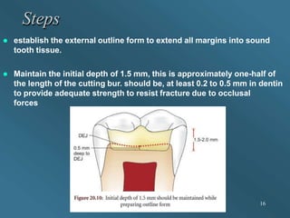
2. Key principles of tooth preparation for amalgam restorations include establishing an outline form that extends the cavity margins into sound tooth structure. The cavity should have a primary resistance form and features like cavosurface margins, reverse curves, and retention forms or locks to resist forces and retain the restoration.
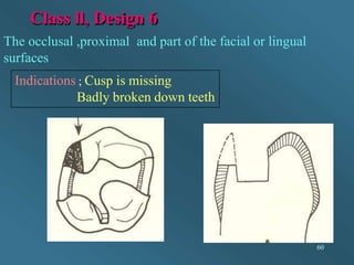
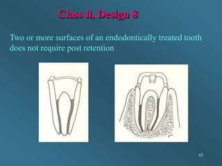
3. Specific cavity preparations are described for different classes of cavities, including designs for single surface Class I cavities, multi-surface Class I cavities, various Class II cavity designs for proximal lesions