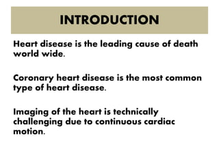
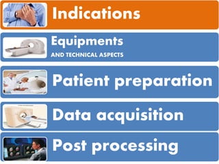
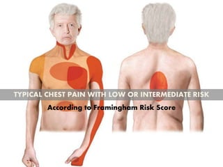
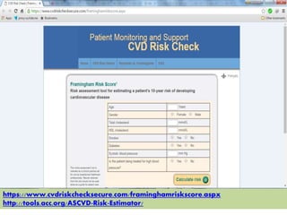
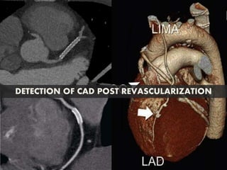
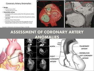
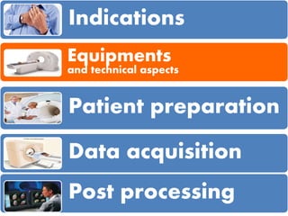
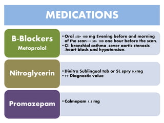
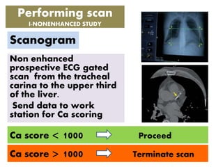
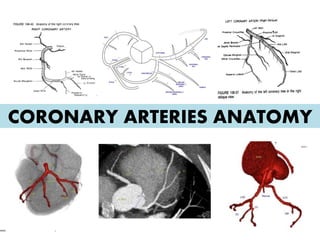
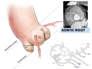
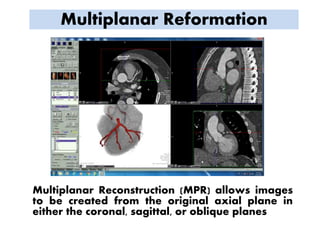
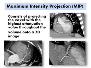
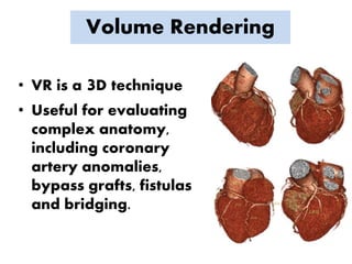
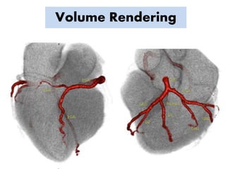
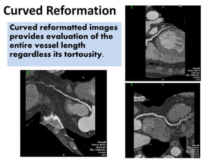
BASICS OF
CORONARY CT ANGIOGRAPHY
Dr. Mohamed Abdelfattah Youssef
Assistant lecturer of radio diagnosis
INTRODUCTION
Heart disease is the leading cause of death
world wide.
Coronary heart disease is the most common
type of heart disease.
Imaging of the heart is technically
challenging due to continuous cardiac
motion.
Indications
Equipments
AND TECHNICAL ASPECTS
Patient preparation
Data acquisition
Post processing
Atypical chest pain
TYPICAL CHEST PAIN WITH LOW OR INTERMEDIATE RISK
According to Framingham Risk Score
https://www.cvdriskchecksecure.com/framinghamriskscore.aspx
http://tools.acc.org/ASCVD-Risk-Estimator/
DETECTION OF CAD POST REVASCULARIZATION
ASSESSMENT OF CORONARY ARTERY
ANOMALIES
Indications
Equipments
and technical aspects
Patient preparation
Data acquisition
Post processing
Equipments
64 MSCT or higher with
ECG gating
Injector (Dual head)
Workstation with cardiac
dedicated software
TEMPORAL RESOLUTION
Its the duration of time for acquisition of a
single frame of a dynamic process.
It depends on speed of gantry rotation
Gantry rotation
Spatial resolution
The ability of the imaging modality to
differentiate two objects.
Determined by minimum slice thickness of the machine
ECG gating
The least cardiac motion occurs during diastole
Gating techniques are used to improve
temporal resolution and minimize imaging
artifacts caused by cardiac motion
10% 20% 0%90%80%70%60%50%40%30%
ECG gating techniques
Prospective ECG triggering :
ECG signal is used to control scanning, so that X rays are generated and
projection data are acquired only during cardiac diastole.
Retrospective ECG triggering :
Every position of the heart must be covered by a detector row at every
point during the cardiac cycle continuously and the ECG signal is
simultaneously recorded
10% 20% 0%90%80%70%60%50%40%30%
Prospective ECG gating
10% 20% 0%90%80%70%60%50%40%30%
Retrospective ECG gating
As image
reconstruction
depends on ECG
any kind of
arrhythmia will
interrupt image
reconstruction
causing artifacts
Why dual head injectors?
Push contrast from connectors and venous
circulation  20 -40 % contrast saving
Improves peak enhancement and bolus
arrival
Wash of contrast from
right side of the heart
Decrease streak artifact
due to contrast pooling
Better visualization of RCA
Why dual head injectors?
Indications
Equipments
Patient preparation
Data acquisition
Post processing
PATIENT PREPARATION
BEFORE SCAN
24 – 48 Hrs before scan
Stop
Don’t stop other medications.
Kidney function test
Serum creatinine
Fasting 8hours prior to exam
History
Consent
Gown
Cannula
Reassurance  Sedation
Breathing exercise
Vital data
Patient Positioning and ECG Leads Attachment
Heart rate control
PATIENT PREPARATION
AT DAY OF
SCAN
MEDICATIONS
•Oral :50- 100 mg Evening before and morning
of the scan→ 50- 100 one hour before the scan.
•CI: bronchial asthma ,sever aortic stenosis
,heart block and hypotension.
B-Blockers
Metoprolol
•Dinitra Sublingual tab or SL spry 0.4mg
•?? Diagnostic valueNitroglycerin
•Calmepam 1.5 mg
Promazepam
?
? ?
?
?
?
Indications
Equipments
Patient preparation
Data acquisition
Post processing
Performing scan
I-NONENHANCED STUDY
Non enhanced
prospective ECG gated
scan from the tracheal
carina to the upper third
of the liver.
Send data to work
station for Ca scoring
Ca score > 1000 Terminate scan
Ca score < 1000 Proceed
Scanogram
• ROI over ascending /
descending aorta
• Automated bolus trigger
• A threshold of 100-120 HU
• Pro/retrospective ECG gating
• Maximum Gantry Rotation
speed and collimation
• Rate of injection : 5 – 6 mL/sec
Performing scan
II-ENHANCED STUDY
80 -100 cc of high concentration of
nonionic contrast media 350–370 mg of
iodine per milliliter is used followed by
40 cc of saline.
Ca scoring value
It was initially invented to Predict the risk of
CAD in the future
Predicts the diagnostic value of coronary CTA
Ca scoring
Interpretation
PROTOCOL MODULATION FOR
POST CABG Patients
Ca score is not
needed.
Scan extends from
the upper chest to
the upper 13 of the
liver.
All outpatients who receive study-
related medication are monitored (ie,
kept in the waiting area) for 30 minutes
after scanning.
Indications
Equipments
Patient preparation
Data acquisition
Post processing
CORONARY ARTERIES ANATOMY
AORTIC ROOT
CORONARY ANATOMY
It usually bifurcates
into left anterior
descending
and
left circumflex
arteries
Left coronary artery
LEFT MAIN artery
(LM)
It arises from the
left posterior aortic
sinus
The LM and its bifurcation are covered by PA
It runs
downwards in
the anterior
inter-ventricular
groove
Left coronary artery
Left anterior descending
artery (LAD)
CORONARY ANATOMY
The LAD artery
gives rise to a
variable
number of
diagonal
branches which
lie on the
lateral aspect
of the left
ventricle.
CORONARY ANATOMY Left coronary artery
DIAGONAL branches
(D1,D2,…..)
The circumflex
artery turns
backwards to run
in the left
atrioventricular
groove
Left coronary artery
LEFT CIRCUMFLEX artery
(LCx)
CORONARY ANATOMY
In the atrioventricular
groove the circumflex
artery is often
covered by the
auricle of the left
atrium
The LCx gives
rise to a variable
number of
marginal
branches, which
run on the lateral
aspect of the left
ventricle
Left coronary artery
OBTUSE MARGINAL BRANCHES
(OM1,OM2,…..)
CORONARY ANATOMY
Left coronary artery
RAMUS INTERMEDIUS artery
CORONARY ANATOMY
In one-third of
population the
left
main coronary
artery trifurcates
into the LAD, left
circumflex,
and an
intermediate
artery,
CORONARY ANATOMY
Normally arises from
the right coronary
sinus (CS) and
courses in the right
AV groove toward
the crux
posterior lateral
branch and posterior
descending artery.
RIGHT CORONARY artery
(RCA)
of the heart
where it
usually
divides into
LA RA
POSTERIOR
VIEW
Dominance
The coronary artery that gives rise to the
PDA and PLB is referred to as the
“dominant” artery.
Artery Dominance
percentage
RCA 70%
LCx 10%
RCA and LCx
(Co dominant)
20%
AXIAL ANATOMY
Multiplanar Reformation
Multiplanar Reconstruction (MPR) allows images
to be created from the original axial plane in
either the coronal, sagittal, or oblique planes
Maximum Intensity Projection (MIP)
Consists of projecting
the voxel with the
highest attenuation
value throughout the
volume onto a 2D
image
Volume Rendering
• VR is a 3D technique
• Useful for evaluating
complex anatomy,
including coronary
artery anomalies,
bypass grafts, fistulas
and bridging.
Volume Rendering
Curved Reformation
Curved reformatted images
provides evaluation of the
entire vessel length
regardless its tortousity.
Basics of CCTA

Basics of CCTA

Editor's Notes

  • #11 Dual head :to inject 40 cc of saline after contrast injection – wash of right side of the heart --- better RCA visualization
  • #12 It depends on speed of gantry rotation Nowadays machines have reached the maximum speed that can be achieved. 165 ms Dual source 85 ms
  • #14 Determined by minimum slice thickness of the machine
  • #27 Below 60 B/min Ability hold breath + HR changes during breath hold Discuss steps of examination Sensation of warmth during die injection Good breath hold is crucial to exam quality Intravenous access is preferably established in a cubital vein. An access site in the right arm should be chosen to prevent streak artifacts that arise from high-attenuating contrast mate- Figure 1 Figure 1: Contrast-enhanced retrospectively ECG-gated 64-section coronary CT angiography in 58-year-old man with dizziness at exertion and risk factors for coronary artery disease. Right anterior oblique views of left coronary artery tree are shown. (a) Curved multiplanar reformation (MPR) shows about 60% stenosis (arrow) of the proximal first diagonal branch caused by noncalcified plaque. (b) Conventional coronary angiogram findings confirm the presence of the lesion in a (arrow), which was subsequently treated with stent placement. HOWI DO IT: Coronary CT Angiography Schoepf et al 50 Radiology: Volume 244: Number 1—July 2007 rial in the left subclavian vein from interfering with evaluation of the left internal mammary arterial origin— 5–6 mL/sec, an 18-gauge or larger catheter should be used whenever possible.
  • #28 orthostatic hypotension
  • #31 This consists of a continuous scan on a single axial slice. On this image, a region of interest (ROI) is placed at the aortic level which examines the Hounsfield units during the passage of the contrast agent. When a predetermined value of units is accomplished (130–150 HU)
  • #32 Scan automatically starts when the density at the region of interest reaches the predetermined threshold
  • #39 Society of Cardiovascular Computed Tomography (SCCT) coronary segmentation diagram