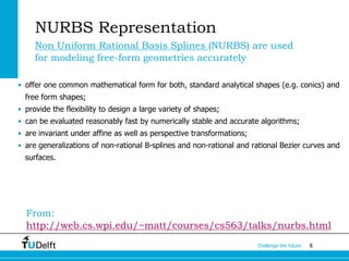
The document discusses the fundamentals of Non-Uniform Rational B-Splines (NURBS) in the context of 3D geometry representations for fields such as architectural engineering and construction (AEC). It covers various types of geometric models, advantages and disadvantages of NURBS, and their mathematical underpinnings for accurately modeling free-form geometries. Additionally, it touches on parametric curves, surface continuity, and curvature analysis in relation to NURBS representation.

![2Challenge the future
[Geometric, Topologic] Spatial Data Models Representations
• Computer Graphics (mainly concerned with visualization)
• Computational Geometry (algorithmic geometry)
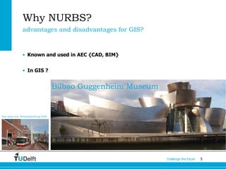
• AEC {CAD, CAM, BIM} (architectural engineering and construction)
• CAD=: Computer Aided Design
• CAM=: Computer Aided Manufacturing
• BIM=: Building Information Modeling
• GIS: how can we represent geometric objects in large scale properly and
consistently?
Different terminologies and jargons! Some common grounds](https://image.slidesharecdn.com/nurbsfpzngeo1004-160130163613/85/On-NURBS-Geometry-Representation-in-3D-modelling-2-320.jpg)
![3Challenge the future
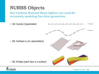
Categories of 3D Geometry Representations
• Volume Representation:
1. Tetrahedral Meshes
2. Voxel Models
• Boundary Representation:
[AKA Surface Representation]
1. Polygon Mesh Models (Simple Brep)
2. [complex] B-rep* Models (NURBS patches)
Interior included or only the closure ? A note on our terminology
* B-rep here refers to a specific class of boundary representations composed of advanced faces (as implemented in Rhino):
• ISO 10303-514 Advanced boundary representation, a solid defining a volume with possible voids that is composed by
advanced faces
• ISO 10303-511 Topologically bounded surface, definition of an advanced face, that is a bounded surface where the surface is
of type elementary (plane, cylindrical, conical, spherical or toroidal), or a swept surface, or b spline surface. The boundaries
are defined by lines, conics, polylines, surface curves, or b spline curves](https://image.slidesharecdn.com/nurbsfpzngeo1004-160130163613/85/On-NURBS-Geometry-Representation-in-3D-modelling-3-320.jpg)
![4Challenge the future
Boundary Representation
Representing high dimensional objects with lower dimensional primitives
1. Polygon Mesh ≡ Simple B-rep=composed of straight/flat elements
We will discuss them later in depth
1. NURBS patches ≡[complex] B-rep*=composed of curved elements](https://image.slidesharecdn.com/nurbsfpzngeo1004-160130163613/85/On-NURBS-Geometry-Representation-in-3D-modelling-4-320.jpg)
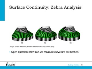
![11Challenge the future
NURBS interpolation
All contenet from Raja Issa
[Essential Mathematics for Computational Design]](https://image.slidesharecdn.com/nurbsfpzngeo1004-160130163613/85/On-NURBS-Geometry-Representation-in-3D-modelling-11-320.jpg)