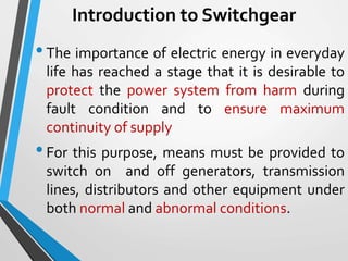
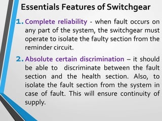
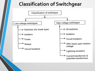
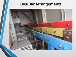
SWITCHGEAR AND PROTECTION
ENGINEERING
EEB 4204
Lecture 02
SWITCHGEAR
Introduction to Switchgear
•The importance of electric energy in everyday
life has reached a stage that it is desirable to
protect the power system from harm during
fault condition and to ensure maximum
continuity of supply
•For this purpose, means must be provided to
switch on and off generators, transmission
lines, distributors and other equipment under
both normal and abnormal conditions.
Introduction to Switchgear
•This is achieved by apparatus called
switchgear
•A switchgear essentially consists of switching
and protecting devices such as switches, fuses,
circuit breaker, relays, isolators, auto-recloser
etc.
•The apparatus used for switching, controlling,
and protecting the electrical circuits and
equipments is called switchgear
Essentials Features of Switchgear
1.Complete reliability - when fault occurs on
any part of the system, the switchgear must
operate to isolate the faulty section from the
reminder circuit.
2.Absolute certain discrimination – it should
be able to discriminate between the fault
section and the health section. Also, to
isolate the fault section from the system in
case of fault. This will ensure continuity of
supply.
Essentials Features of Switchgear
3. Quick Operation- must operates quickly so
that no damage is done in any equipment in
case of fault.
4. Provision for control manual– in case the
electrical or electronics control fails, the
necessary operation can be carried out through
manual control.
Essentials Features of Switchgear
5. Provision for instruments – may be in form
of ammeter or voltmeter on the unit itself or the
necessary current and voltage transformers for
connecting to the main switchboard or a
separate instrument panel.
Classification of Switchgear
Isolating Switch (Isolator)
•Isolating switch is an apparatus which makes
a visible break in the circuit.
•Isolator is used to open (or close) a circuit
either when negligible current is interrupted
(or established) or
•When no significant change in the voltage
across the terminals of each pole of the
isolator will result from the operation.
Isolating Switch (Isolator)
•According to number of poles isolators may be
classified as single pole, double poles isolators
and three pole isolators.
•According to type of service, isolators may be
classified as indoor type or outdoor type
Isolating Switch (Isolator)
Air BreakerType
•This switch is also known as air breaker type
circuit breaker. In this type, air at
atmospheric pressure is used as
extinguishing medium.
•In air-breakers, the principle of high
resistance is employed for arc interruption.
•The arc resistance is increased by
lengthening, splitting and cooling arc.
Air BreakerType
•AC air breaker are available in the range 400V
to 12kV. Also, used in DC circuit up to 12kV.
They are extensively used;
With electric furnaces,
With large motors requiring frequent starting,
 In a place where chances of fire hazard exist.
Lightning Arresters
•Lightning arresters a re also known as surge
diverter or surge arresters.
•They connected between the line and
ground at the substation and always acts as
in shunt (parallel) with the equipment to be
protected.
•Perform their protective function by
providing a low impedance path for the
surge currents
Lightning Arresters
• So that the surge arrester’s protective level is
less than the surge voltage withstanding
capacity of the insulation of equipment to be
protected.
Bus-Bar Arrangements
•When a number of generators and feeders
operating at the same voltage have to be
directly connected electrically
•Bus-bars are used as common electrical
components.
•Bus-bars are copper rod or thin walled tubes
and operate at constant voltage.
Bus-Bar Arrangements
1. Single bus-bar system
2.Single bus-bar system with sectionalization
3. Duplicated bus-bar system
Single Bus-bar System
•It is the simplest design of bus-bar systems
•It is used in small outdoor stations having
relatively few outgoing and incoming feeders
and lines.
•In single bus-bar system, each generator and
feeder is controlled by circuit breaker.
•The isolators permit to isolate generators,
feeders and circuit breaker from the bus-bar
for maintenance.
Single Bus-bar System
1. It has low initial cost
2.Less maintenance
3. Simple operation
Advantages
Single Bus-bar System
1. The bus-bar cannot be cleaned, tested or
repaired without de-energising the whole
system.
2. If a fault occurs on the bus bar itself, there is
complete interruption of supply.
3. Any fault on then system is fed by all the
generating capacity, resulting in very large
fault currents.
Disadvantages
Single Bus-bar System with
Sectionalisation
•In large generating stations where several
units are installed.
•It is common to sectionalize the bus so that
fault on any section of then bus-bar will not
cause complete shutdown.
•The bus-bar divided into two section
connected by circuit breaker and isolators.
Single Bus-bar System with
Sectionalisation
Single Bus-bar System with
Sectionalisation
1. If a fault occurs on any section of the bus-bar,
that section can be isolated without
affecting the supply of other section.
2.If a fault occurs on any feeder, the fault
current is much lower than unsectionalise
bus-bar.
3. Eliminate the possibility of complete shut
down during repair or maintenance of any
section on bus-bar.
Advantages
Single Bus-bar System with
Sectionalization
1. A circuit breaker should be used as
sectionalizing switch. So that uncoupling of
the bus-bars may be carried out safely during
load transfer.
2. Moreover, the circuit breaker itself should be
provided with isolators on both sides so that
its maintenance can be done while the bus-
bars are live.
Points to note
Duplicated Bus-bar System
•In large stations, it is important that
breakdown and maintenance should interfere
as little ae possible with continuity of supply.
•In to achieve this objective, duplicate bus-bar
system is used in important substations.
•Such a system consists of two bus-bar, a main
bus-bar and spare bus-bar.
•Each generator ad feeder may be connected to
either bus-bar with the help of bus coupler
which consists of circuit breaker and isolators.
Duplicated Bus-bar System
•Service is interrupted during switch from one
bus-bar to another.
•However, if it were desired to switch a circuit
from one to another without interruption n
there would have two circuit breakers per
circuit.
•Such a arrangement will be to expensive.
Duplicated Bus-bar System
1. If repair ad maintenance are to be carried on
main bus bar, the supply need not be
interrupted as the entire load can be
transferred to the spare bus-bar.
2.The testing of feeder circuit breaker can be
done by putting them on spare bus bar, thus
keeping main bus bar undisturbed
3. If a fault occurs on the bus bar, the continuity
of the supply to the circuit can be maintained
by transferring it to the other bus bar.
Advantages
Duplicated Bus-bar System
Switchgear Accommodation
•Depending upon the voltage to be handled,
switchgear may be broadly classified into
1) Outdoor type
2) Indoor type
•For voltage beyond 66kV, switchgear
equipment is installed outdoor.
Switchgear Accommodation
•It is because for such voltages, the clearance
between conductors and space required for
switches, circuit breaker, transformer and
other equipment become so great that it is not
economical to install all such equipment
indoor.
•For voltage below 66kV, switchgear is
generally installed indoor because of
economical considerations.
Fault in Power System
•The normal path of the electric current is from
the power source through copper (or
aluminum) conductors in generators,
transformers and transmission lines to the
load
• It is confined to this path by insulation. The
insulation, however, may break down, either
by the effect of temperature and age or by a
physical accident,
Fault in Power System
•So that the current then follows an abnormal
path generally known as Short Circuit or Fault
•Any abnormal operating state of a power
system is known as FAULT.
•Faults in general consist of short circuits as
well as open circuits.
•Open circuit faults are less frequent than
short circuit faults, and often they are
transformed in to short circuits by subsequent
events.
Fault in Power System
•A fault occurs when two or more conductors
that are normally operate with potential
difference come in contact with each other.
•This fault may be caused by:
1. Sudden failure of a piece of equipment
2. Accidental damage or short circuit of overhead
lines
3. Insulation failure resulting from lighting surges.
Fault in Power System
•The short circuited fault in three phase system
can be classified into two categories;
1. Symmetrical faults
2. Unsymmetrical faults
•Symmetrical faults gives rise to fault current.
Equal fault current with 120o displacement.
•Example of symmetrical fault is when all three
conductors of a three phase lie brought
together simultaneously into short circuit.
Fault in Power System
•Unsymmetrical faults give rise to
unsymmetrical current. Unequal line currents
with unequal displacement.
•The unsymmetrical faults may take the
following form;
1. Single line to ground fault
2. Line to line fault
3. Double line to ground fault
Fault in Power System
•The great majority faults on the power system
are of unsymmetrical nature, the most
common type being a short circuit from one
line to ground.
Fault in Power System
•The open circuited fault in three phase system
can be classified into two categories;
1. Single phase open circuit
2. Two phases open circuit
3. Three phase open circuit
Fault in Power System
•In terms of seriousness of consequences of a
fault, short circuits are of far greater concern
than open circuits, although some open
circuits present some potential hazards to
personnel
Consequences of occurrence of fault
1. Damage to the equipment due to abnormally
large and unbalanced currents and low
voltages produced by the short circuit
2.Explosions may occur in the equipments
which have insulating oil, particularly during
short circuits.This may result in fire and
hazardous conditions to personnel and
equipments
Consequences of occurrence of fault
3. Individual generators with reduced voltage in
a power station or a group of generators
operating at low voltage may lead to loss of
synchronism, subsequently resulting in
islanding.
THE END OFTHE
TOPIC

Switchgear and protection engineering Lecture 02.pptx

  • 1.
  • 2.
  • 3.
    Introduction to Switchgear •Theimportance of electric energy in everyday life has reached a stage that it is desirable to protect the power system from harm during fault condition and to ensure maximum continuity of supply •For this purpose, means must be provided to switch on and off generators, transmission lines, distributors and other equipment under both normal and abnormal conditions.
  • 4.
    Introduction to Switchgear •Thisis achieved by apparatus called switchgear •A switchgear essentially consists of switching and protecting devices such as switches, fuses, circuit breaker, relays, isolators, auto-recloser etc. •The apparatus used for switching, controlling, and protecting the electrical circuits and equipments is called switchgear
  • 5.
    Essentials Features ofSwitchgear 1.Complete reliability - when fault occurs on any part of the system, the switchgear must operate to isolate the faulty section from the reminder circuit. 2.Absolute certain discrimination – it should be able to discriminate between the fault section and the health section. Also, to isolate the fault section from the system in case of fault. This will ensure continuity of supply.
  • 6.
    Essentials Features ofSwitchgear 3. Quick Operation- must operates quickly so that no damage is done in any equipment in case of fault. 4. Provision for control manual– in case the electrical or electronics control fails, the necessary operation can be carried out through manual control.
  • 7.
    Essentials Features ofSwitchgear 5. Provision for instruments – may be in form of ammeter or voltmeter on the unit itself or the necessary current and voltage transformers for connecting to the main switchboard or a separate instrument panel.
  • 8.
  • 9.
    Isolating Switch (Isolator) •Isolatingswitch is an apparatus which makes a visible break in the circuit. •Isolator is used to open (or close) a circuit either when negligible current is interrupted (or established) or •When no significant change in the voltage across the terminals of each pole of the isolator will result from the operation.
  • 10.
    Isolating Switch (Isolator) •Accordingto number of poles isolators may be classified as single pole, double poles isolators and three pole isolators. •According to type of service, isolators may be classified as indoor type or outdoor type
  • 11.
  • 12.
    Air BreakerType •This switchis also known as air breaker type circuit breaker. In this type, air at atmospheric pressure is used as extinguishing medium. •In air-breakers, the principle of high resistance is employed for arc interruption. •The arc resistance is increased by lengthening, splitting and cooling arc.
  • 13.
    Air BreakerType •AC airbreaker are available in the range 400V to 12kV. Also, used in DC circuit up to 12kV. They are extensively used; With electric furnaces, With large motors requiring frequent starting,  In a place where chances of fire hazard exist.
  • 14.
    Lightning Arresters •Lightning arrestersa re also known as surge diverter or surge arresters. •They connected between the line and ground at the substation and always acts as in shunt (parallel) with the equipment to be protected. •Perform their protective function by providing a low impedance path for the surge currents
  • 15.
    Lightning Arresters • Sothat the surge arrester’s protective level is less than the surge voltage withstanding capacity of the insulation of equipment to be protected.
  • 16.
    Bus-Bar Arrangements •When anumber of generators and feeders operating at the same voltage have to be directly connected electrically •Bus-bars are used as common electrical components. •Bus-bars are copper rod or thin walled tubes and operate at constant voltage.
  • 17.
  • 18.
  • 19.
    Bus-Bar Arrangements 1. Singlebus-bar system 2.Single bus-bar system with sectionalization 3. Duplicated bus-bar system
  • 20.
    Single Bus-bar System •Itis the simplest design of bus-bar systems •It is used in small outdoor stations having relatively few outgoing and incoming feeders and lines. •In single bus-bar system, each generator and feeder is controlled by circuit breaker. •The isolators permit to isolate generators, feeders and circuit breaker from the bus-bar for maintenance.
  • 21.
  • 22.
    Single Bus-bar System 1.It has low initial cost 2.Less maintenance 3. Simple operation Advantages
  • 23.
    Single Bus-bar System 1.The bus-bar cannot be cleaned, tested or repaired without de-energising the whole system. 2. If a fault occurs on the bus bar itself, there is complete interruption of supply. 3. Any fault on then system is fed by all the generating capacity, resulting in very large fault currents. Disadvantages
  • 24.
    Single Bus-bar Systemwith Sectionalisation •In large generating stations where several units are installed. •It is common to sectionalize the bus so that fault on any section of then bus-bar will not cause complete shutdown. •The bus-bar divided into two section connected by circuit breaker and isolators.
  • 25.
    Single Bus-bar Systemwith Sectionalisation
  • 26.
    Single Bus-bar Systemwith Sectionalisation 1. If a fault occurs on any section of the bus-bar, that section can be isolated without affecting the supply of other section. 2.If a fault occurs on any feeder, the fault current is much lower than unsectionalise bus-bar. 3. Eliminate the possibility of complete shut down during repair or maintenance of any section on bus-bar. Advantages
  • 27.
    Single Bus-bar Systemwith Sectionalization 1. A circuit breaker should be used as sectionalizing switch. So that uncoupling of the bus-bars may be carried out safely during load transfer. 2. Moreover, the circuit breaker itself should be provided with isolators on both sides so that its maintenance can be done while the bus- bars are live. Points to note
  • 28.
    Duplicated Bus-bar System •Inlarge stations, it is important that breakdown and maintenance should interfere as little ae possible with continuity of supply. •In to achieve this objective, duplicate bus-bar system is used in important substations. •Such a system consists of two bus-bar, a main bus-bar and spare bus-bar. •Each generator ad feeder may be connected to either bus-bar with the help of bus coupler which consists of circuit breaker and isolators.
  • 29.
    Duplicated Bus-bar System •Serviceis interrupted during switch from one bus-bar to another. •However, if it were desired to switch a circuit from one to another without interruption n there would have two circuit breakers per circuit. •Such a arrangement will be to expensive.
  • 30.
  • 31.
    1. If repairad maintenance are to be carried on main bus bar, the supply need not be interrupted as the entire load can be transferred to the spare bus-bar. 2.The testing of feeder circuit breaker can be done by putting them on spare bus bar, thus keeping main bus bar undisturbed 3. If a fault occurs on the bus bar, the continuity of the supply to the circuit can be maintained by transferring it to the other bus bar. Advantages Duplicated Bus-bar System
  • 32.
    Switchgear Accommodation •Depending uponthe voltage to be handled, switchgear may be broadly classified into 1) Outdoor type 2) Indoor type •For voltage beyond 66kV, switchgear equipment is installed outdoor.
  • 33.
    Switchgear Accommodation •It isbecause for such voltages, the clearance between conductors and space required for switches, circuit breaker, transformer and other equipment become so great that it is not economical to install all such equipment indoor. •For voltage below 66kV, switchgear is generally installed indoor because of economical considerations.
  • 34.
    Fault in PowerSystem •The normal path of the electric current is from the power source through copper (or aluminum) conductors in generators, transformers and transmission lines to the load • It is confined to this path by insulation. The insulation, however, may break down, either by the effect of temperature and age or by a physical accident,
  • 35.
    Fault in PowerSystem •So that the current then follows an abnormal path generally known as Short Circuit or Fault •Any abnormal operating state of a power system is known as FAULT. •Faults in general consist of short circuits as well as open circuits. •Open circuit faults are less frequent than short circuit faults, and often they are transformed in to short circuits by subsequent events.
  • 36.
    Fault in PowerSystem •A fault occurs when two or more conductors that are normally operate with potential difference come in contact with each other. •This fault may be caused by: 1. Sudden failure of a piece of equipment 2. Accidental damage or short circuit of overhead lines 3. Insulation failure resulting from lighting surges.
  • 37.
    Fault in PowerSystem •The short circuited fault in three phase system can be classified into two categories; 1. Symmetrical faults 2. Unsymmetrical faults •Symmetrical faults gives rise to fault current. Equal fault current with 120o displacement. •Example of symmetrical fault is when all three conductors of a three phase lie brought together simultaneously into short circuit.
  • 38.
    Fault in PowerSystem •Unsymmetrical faults give rise to unsymmetrical current. Unequal line currents with unequal displacement. •The unsymmetrical faults may take the following form; 1. Single line to ground fault 2. Line to line fault 3. Double line to ground fault
  • 39.
    Fault in PowerSystem •The great majority faults on the power system are of unsymmetrical nature, the most common type being a short circuit from one line to ground.
  • 40.
    Fault in PowerSystem •The open circuited fault in three phase system can be classified into two categories; 1. Single phase open circuit 2. Two phases open circuit 3. Three phase open circuit
  • 41.
    Fault in PowerSystem •In terms of seriousness of consequences of a fault, short circuits are of far greater concern than open circuits, although some open circuits present some potential hazards to personnel
  • 42.
    Consequences of occurrenceof fault 1. Damage to the equipment due to abnormally large and unbalanced currents and low voltages produced by the short circuit 2.Explosions may occur in the equipments which have insulating oil, particularly during short circuits.This may result in fire and hazardous conditions to personnel and equipments
  • 43.
    Consequences of occurrenceof fault 3. Individual generators with reduced voltage in a power station or a group of generators operating at low voltage may lead to loss of synchronism, subsequently resulting in islanding.
  • 44.