This document discusses electrical protection systems for power stations. It explains the need for protection against faults like overcurrent and earth faults to isolate faulty equipment quickly. Detection of faults is done by measuring changes in current and voltage using transformers and relays. Different types of protection relays and schemes are described to discriminate faults and provide backup protection for transformers, circuits, busbars and generators.

![richardsm
ith@
asia.com
Residual Voltage The vector sum of the voltages to earth of the three phase
conductors. The secondary equivalent is obtained by connecting the three
VT secondaries in series.
Restraint A relay may be hindered from operating by some quantity, such as
voltage. it is then said to be given (voltage) restraint. An impedance
relay is restrained by voltage, operated by current. The current tending
to close the contacts, the voltage to open them.
Sensitivity A protective scheme is sensitive when it will respond to very small
internal faults, but note that extreme sensitivity is usually accompanied
by poor stability.
item[Selectivity or discrimination] The protection in any zone is said to
discriminate or be selective, when it can distinguish between an internal
fault within the zone and an external (through) fault in another zone. The
protection should trip on an internal fault but ignore all external faults
and normal load current. A scheme that lacks discrimination will cause
unnecessary disconnection of healthy plant and circuits.
Signal Link A communication link between two substations used for protec-
tion purposes, usually to close (or open) a contact at the remote station.
The link may be by metallic wires (pilots), carrier over pilot wires, power
line carrier, radio, etc.
Speed of Operation The longer a fault is allowed to persist, the greater the
damage that may be caused. In the case of a high current fault close to
a generator, synchronisation to the system may be lost. Fast operation
should not, however, be sought at the expense of selectivity or reliability.
Stability Protection is stable if it does not respond to faults outside the pro-
tected zone, i.e. it operates only for those faults it is designed to operate
for.
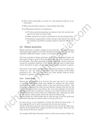
Unit Protection Protection which protects a precisely defined area of the
power system. It responds only to faults within that defined area. Typical
examples are differential protection, busbar protection, Buchholz relay.
VT Voltage Transformer
6](https://image.slidesharecdn.com/fce4581e-b8aa-4f8b-9ad4-b7b3b87410f6-160721041346/85/Power-Station-Electrical-Protection-11-320.jpg)