
Recommended
Recommended
More Related Content
What's hot
What's hot (20)
Similar to Building construction ii
Similar to Building construction ii (20)
More from Jia Xin Chee
More from Jia Xin Chee (13)
Recently uploaded
Recently uploaded (20)
Building construction ii
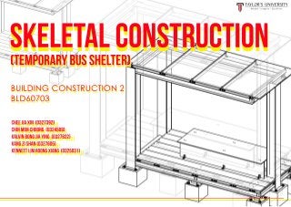
- 1. Skeletal Construction(TEMPORARY BUS SHELTER) cHEE JIA XIN (0327392) cHIN mAN CHONG (0324509) kAlvin bONG jIA yING (0327822) kANG zI sHAN (0327605) kENNETT lIM rOONG xIANG (0325031) (TEMPORARY BUS SHELTER) Skeletal Construction cHEE JIA XIN (0327392) cHIN mAN CHOoNG (0324509) kAlvin bONG jIA yING (0327822) kANG zI sHAN (0327605) kENNETT lIM rOONG xIANG (0325031) BUILDING CONSTRUCTION 2 BLD60703 BUILDING CONSTRUCTION 2 BLD60703
- 2. 03IntroductionTABLE OF CONTENTS 04 Design Considerations Design Intention Orthographic Drawings Construction Process - Floor Structure / Steel Framing & Joists - Foundation / Concrete Pad Footing - Flooring & Bench / Merbau Wood Decking & Seating - Column / I-Beam Column - Roof Structure / Steel Framing, Beam & Joists - Roofing / Polycarbonate (PC) Plastics Sheet- Roofing / Polycarbonate (PC) Plastics Sheet Steel Skeleton Frame Structure - Materiality - Loads & Forces - Exploded Axonometric Construction Details Analysis of Design Load Test Summary Renderings References Design Development 05 06 07 09 10 25 29 15 30 32 33
- 3. 01INTRODUCTION In this project, we are tasked to design and construct a temporary bus shelter that focuses on principle of skeleton frames and their joints. The bus shelter required is to have a maximum height of 600mm and a maximum base of 400mm x 800mm, reflecting a practical usage based on portability and comfort as well as functioning to provide optimal shading from rain and sun. OBJECTIVESOBJECTIVES In order to assemble a strong and stable structure, we are to understand the fundamentals of skeletal system as well as the structural support and joint connection with one another. In addition, to understand how structure bears different loads without compromising structural integrity of the bus shelter as well as safety purpose of the users. Law of static, force, stress and materiality are essential considerations, contributing to building’s strength, stabilityessential considerations, contributing to building’s strength, stability and stiffness. idea sketch - initial
- 4. 02DESIGN iNTENTION We intend to design an appropriate shelter with I-beams by connecting them to form as a whole that meets common needs whilst providing understanding and function of a designated bus shelter as wel as meeting brief of structural and skeletal support to uphold the weight acting on the bus shelter. Derived from the shape of cube and cuboid, the bus shelter reveals its simplicity by showing connection of beam to beamsreveals its simplicity by showing connection of beam to beams and columns of the structure by using mainly I-beams. The I-beams’ integrity is aimed to withstand high load pressure, both dead and live load as well as wind load forces applied. + cube cuboid 04 idea sketch - massing
- 5. 03design considerations 05 capacity accessibility weather resistance stability openness circulation flow SUNLIGHT LOAD TRANSFER air flow RAIN Able to accomodate 5-6 persons whilst providing resting comfort Wide entrance exposure allows free movement in where pedestrians access the area from surrounding openings of the bus shelter Able to resist local climate, allowing direct sunlight and rainfall acted on the bus shelter to provide protection to pedestrians Uniform arrangement order of structural components to resist horizontal and vertical loads to prevent lifting or collapsing Provides visibility towards traffic conditions and oncoming vehicles as well as maximizes optimal air flow in and out of the structure Selection of choice of materials to have high strength and durability, readily available, and less harmful to environment materiality
- 6. 04DESIGN DEVELOPMENT 01. initial idea 06 02. initial structure 03. development 04. final design Two elements, folding plane and upright vertical plane conjoint together to form a covered space below as well as massing of the entire bus shelter Horizontal roof joists are added along with the vertical columns to distribute evenly the weight and loads applied on it, connecting to the single standing column. Horizontal joists are added onto roof joists and vertical columns to add protection and appearance to the bus shelter Proper detailed columns and beams arrangement for efficient loads transfer and stability of the skeleton frames structure
- 7. 05oRTHOGRAPHIC DRAWINGS floor plan roof plan Scale 1:25 Scale 1:25 B b’ B b’ A A’ A A’
- 8. front ELEVATION SECTION A-A’ SECTION B-B’side ELEVATION Scale 1:30 Scale 1:30 Scale 1:30 Scale 1:30
- 9. 06exploded axonometric 09 LEGEND: 1/ Polycarbonate Sheet Roofing 2/ Roof Joist 3/ Roof Framing 4/ Timber Seating 5/ Timber Decking 6/ Floor Joist6/ Floor Joist 7/ I-Beam Column 8/ Roof Beam 9/ I-Beam Post 10/ Ground Beam 11/ Steel Plate 12/ Girder 13/ Concrete Pad Footing13/ Concrete Pad Footing & members of skeleton frames structure 1 3 4 5 6 7 8 11 9 13 2 12 10
- 11. foundation / concrete pad footing floor structure / steel framing 01 Wooden blocks are used as pad footing foundations to represent concrete footings in actual scale model. 01 Long mild steel pieces are welded together to a way it forms an I-beam form. 02 Wooden beam is dimensioned accordingly and cut into desired blocks. 02 The mild steel I-beam is cut down to shorter size using steel cutter chop saw to fit them as posts, ground beams and girders for framing to be connected.connected. 03 All wooden blocks are later sprayed with colored adhesive to represent the materiality of concrete in actual scale model, and then prepared to be used as foundation footings.as foundation footings. 03 All components of steel base framing are assembled and welded to connect them but cleated in actual scale model.
- 12. floor structure / floor joists column / i-beam column 01 Two long rectangular hollow section (RHS) steels are attached together by welding. 01 Long mild steel pieces are welded together following the desired size to form I-beam columns. 02 Double RHS steels are then cut into intended lengths seperately and are later used for floor joists. 02 The mild steel I-beam columns are joined together with the steel skeletal framing of the floor structure by welding to form overall connection of columns and beams.columns and beams. 03 All the floor joists are connected to the skeletal framing of the floor structure to allow timber decking and seating to be placed on. 03 Columns and posts of the structure are then connected to the steel plates by welding and steel plates are screwed to the pad footings.
- 13. flooring & bench / PLYWOOD decking & seating (merbau wood) 01 Plywood plank is measured and prepared to be saw into single plank flooring and three timber pieces for the bench by using hacksaw. 01 All the cut I-beam steel pieces are organized neatly before assembling by welding them to represent it being cleated in actual scale bus shelter. 02 Single plywood plank is laser-cut to reflect each individual timber plank on the flooring that is represented in actual scale bus shelter. 02 A steel roof beam is connected in between two of the columns while the rest are joined together to form a framing. 03 Flooring is then decked to the skeletal framing of the floor structure secured in using cordless drill. Bench is also assembled and secured on top of the floor.top of the floor. 03 The roof framing is then attached to the single vertical column by welding together. roof structure / STEEL framing & beam
- 14. roof structure / roof joists 01 Double RHS steels are rest on the roof steel frame and are welded to it. 01 The acrylic sheet is cut into given dimension that fits and covers the whole structure from above. 02 Placement of the RHS steels on the steel frame are spanned equally among each other. 02 The sheet is placed on top of the roof joists and is secured on by screwing. 03 The steel plates are screwed into the wooden block footings, marking the model’s completion. roofing / Acrylic Sheet (polycarbonate sheet)
- 15. 08construction details 15 floor structure : steel framing & joists The steel base framing with joists makes up the main floor structure of the bus shelter which functions to bear loads vertically to the ground. It is connected with the steel posts and concrete pad footings, allowing timber decking andpad footings, allowing timber decking and bench to sit on it to form a unified skeleton frames structure. steel i-beam type A Function: As primary ground beam, joining the steel posts and concrete pad footings in a single row. Dimensions:Dimensions: Length: 3625MM steel i-beam type b/c/d Function: As girders to join the front and back row of columns, steel posts and foundations. Dimensions:Dimensions: Length for Type B: 1250MM Length for Type C: 1499MM Length for Type D: 746MM e : RECTANGULAR HOLLOW SECTION (RHS) Function: As floor beams/joists to allow the timber decking to connect to it. Dimensions:Dimensions: Length: 1650MM 38MM 1.6MM 75MM 71.8MM BACK FRONT A A B E E EEEE E C D D 150MM 150MM 130MM 7MM 10MM 150MM 150MM 130MM 7MM 10MM
- 16. 16 floor steel framing & joists dimensions 500MM 750MM 1495MM BACK FRONT 1650MM1250MM1000MM 500MM 4000MM 1282MM 425MM 1330.5MM 425MM 288MM 495MM
- 17. floor steel framing & Joists Connections ANGLE BRACKET (a-i) DOUBLE CLEATS WITH 4 BOLTS & NUTS Function: As joint to connect columns and ground beam as well as ground beams and girders Dimensions:Dimensions: Height & Width: 50MM Length: 70MM Thickness: 5MM ANGLE BRACKET SINGLE CLEAT WITH 2 BOLTS & NUTS Function: As joint to connect RHS steels to ground beams Dimensions: Height & Width: 60MMHeight & Width: 60MM Length: 40MM Thickness: 5MM HEX HEAD BOLT & NUT Dimensions: F: 16MM D: 11MM Length: 20MM Head: 6.58MM BACK FRONT 17 a b c d e f g h i
- 18. floor steel framing & Joists Connection details BACK FRONT 18 One surface of steel single cleat is rigidly welded onto the RHS steel CONNECTION BETWEEN FLOOR JOIST AND Girder connection between girder and ground beam Another surface of steel single cleat is bolted onto the ground beam Girder Girder Top flange of the beam is coped to allow top of the beam to be flush with the top of the girder Ground Beam Steel angle cleats are bolted to web of girder and beam Coped Beam Flange Girder Girder Beam
- 19. BACK FRONT SIDE ELEVATION SECTION 19 PAD FOOTING TYPE A Dimensions: Width & Length: 500MM Height: 400MM PAD FOOTING TYPE B Dimensions: Width & Length: 400MM Height: 400MM ANCHOR BOLT WASHER Dimensions: WD: 30MM ND: 28.5MM Steel post Anchor Bolt Steel base plate CONNECTION BETWEEN STEEL PLATE AND PAD FOOTING WH: 6MM NH: 2.2MM D: 19.05MM steel plate TYPE b Dimensions: Width & Length: 300MM Thickness: 5MM A A B B BB B B B A A Height LengthWidth FOUNDATION : CONCRETE PAD FOOTINGS Height LengthWidth steel plate TYPE A Dimensions: Width & Length: 400MM Thickness: 5MM Concrete pad footing
- 20. 20 FLOORING & BENCH : MERBAU WOOD DECKING & SEATING Merbau wood planks Dimensions: Width: 250MM Length: 3500MM Thickness: 25MM CONNECTION BETWEEN TIMBER PLANK AND FLOOR JOIST CONNECTION BETWEEN TIMBER seating and timber PLANK self TAPPING SCREW Dimensions: D1: 11MM D2: 15MM L: 40MM H: 7MM Self Tapping Screw Timber Plank Floor Joist Timber planks are laid above the floor joists to create a finished look for the timber decking. Each timber plank is secured to the floor joists underneath using self-tapping screw, providing a flat and safe surface for pedestrian’s use as wellsurface for pedestrian’s use as well as stabilizing the floor system. ANGLE BRACKET DOUBLE CLEATS WITH 4 BOLTS & NUTS Dimensions: Height & Width: 50MM Length: 70MM Thickness: 5MM Floor Joist Merbau wood planks TYPE B Dimensions: Width: 450MM Length: 2350MM Thickness: 30MM Merbau wood planks TYPE A Dimensions: Width: 800MM Length: 2350MM Thickness: 20MM A A B B B DECKING SEATING Timber Decking Timber Seating HEX HEAD BOLT & NUT Dimensions: F: 16MM D: 11MM Length: 20MM Head: 6.58MM
- 21. 21 COLUMN : I-BEAM STEEL POST & COLUMN C: steel i-beam post Function: Connects concrete pad footings with girders Dimensions: Length: 50MM STEEL I-BEAM COLUMN TYPE A Function: Connects concrete pad footings with roof framing Dimensions: Length: 2800MM STEEL I-BEAM COLUMN TYPE b Function: Connects concrete pad footings with roof framing Dimensions: Length: 2725MM 150MM 150MM 130MM 7MM 10MM 250MM 250MM 230MM 7MM 10MM 250MM 250MM 230MM 7MM 10MM A A B B B B BACK FRONT
- 22. 22 ROOF STRUCTURE : STEEL FRAMING & JOISTS DIMENSIONS 250MM 750MM BACK FRONT 1650MM1250MM 839MM 3750MM 1500MM
- 24. ROOFing : POLYCARBONATE SHEET sheet TYPE A Dimensions: Width: 964MM Length: 1750MM Thickness: 15MM Self Driving Screw Single Cleat Angle Bracket Bolts and Nuts RHS Steel connection between polycarbonate sheets and roof joists sheet TYPE B Dimensions: Width: 840MM Length: 1750MM Thickness: 15MM sheet TYPE C Dimensions: Width: 1106MM Length: 1750MM Thickness: 15MM SELF DRILLING SCREW Dimensions: D1: 4.5MM D2: 5.5MM Length: 32MM Head: 5MM 24 A B B C
- 25. 09ANALYSIS OF DESIGN steel skeleton frame construction Steel skeleton frame structure is a nakedly exposed steel structure which consists of vertical and horizontal members (column and beam) to support the floors, roofs and walls which are attached to the frame.the frame. I-beam columns and I-beam posts make up the vertical members of the structure upholding the weights and loads that are under compressive force. Ground beams, girders, floor joists, steel roof framing and roof joists make up the horizontal members of the structure bearing the loads which act perpendicularly to their lengthto their length. VERTICAL MEMBERS HORIZONTAL MEMBERS
- 26. materiality Hardwood used in a wide range of applications; from construction to indoor and outdoor furniture. Characteristics of Material Chosen: Characteristics of Material Chosen: Characteristics of Material Chosen: Strong and tough amorphous thermoplastic, and some grades are optically transparent. They are easily worked, molded, and thermoformed which suit the aspect for overhead coverings while allowing sunlight to enterwhile allowing sunlight to enter the space below. Reliable, sturdy and economical steel which is easy to manipulate to reform it as another use as well as to provide stability of the construction. - Fire and Heat Resistance - Aesthetic Appearance (Attractive Modern Look) - Easy to Maintain - High Tensile Strength - Lightweight - Durable - Light Transmission - Energy saving - Resist heat and sunlight - Waterproof - Durable - Economical - Natural Insulator (Heat Resistance) - Fast and Efficient to Build With - Low Maintenance - Weather Resistance POLYCARBONATE (PC) PLASTICS MERBAU WOOD STAINLESS STEEL Characteristics of Material Chosen: Most suitable use for footings that supports building and effectively bears load forces vertically to the ground. - Durable - Heat and Water Resistance - Ductile - Non-Permeable CONCRETE
- 28. 28 External loads factor such as live loads and static loads also act on the structure itself. LOADS & FORCES External loads LIVE LOADSSTATIC LOADS (DEAD LOADS) Constant forces of the structure’s permanent elements and components acted on the it for a long duration of time. Moveable loads like pedestrians, wind and rainwater add different intensity of weights/loads onto the structure, therefore varying at different time. Precipitation / Wind Load Human Load Distribution Load Distribution Load Distribution
- 30. 11RENDERINGS
- 32. 12SUMMARY This project task opens us up onto the essential and critical exploration of joints, connections, beams, and columns. The project scale gives us the opportunity to explore and construct an efficient bus shelter that has structural anecdotes and skeletal structure that is practical. Moreover, a good design is also based on the type of choices on materials. Materiality plays a part in determining the overallon materials. Materiality plays a part in determining the overall strength and feasibility of the structure stability. Solid materials like steel used, make great way of designing aspects of withstanding weight and show bare connectivity with one another. Also, type of joints contributed in properly holding all elements in place and how the bus shelter stands. We learnt the characteristics and procedures of construction process and also able to construct a bus stand that meetsprocess and also able to construct a bus stand that meets purpose of a functionable bus shelter which provide use and comfort to users at a small scale. 32
- 33. 13REFERENCES INTERNET SOURCES BOOKS 1. Blanc, A., McEvoy, M. & Plank, R. (1993). Architecture and Construction in Steel. E & FN SPON. 2. Ching, F.D.K. (2014). Building Construction Illustrated. John Wiley & Sons. 3. Chudley, R., Greeno, R., & Hurst, M. (2011). Construction Technology. Harlow: Pearson Education. 4. Lyons, Arthur. (2004). Materials for Architects and Builders (2nd Edition). Oxford Press. 5. Newman, A. (2015). Metal Buildings Systems – Design and Specifications. McGraw-Hill Education. 1. “Polycarbonate Sheets, Multiwall & Roofing Materials.” Edited by Lucid design Corp, Tuflite, Lucid Design, Jan. 2016, retrieved from www.tuflite.com/ blog/types- polycarbonate-roofing-sheets/. 2. steel, w. ,2017. Roofing. [online] westman steel. Retrieved from: http://Westman Steel [PDF]. (n.d.) Canada: Westmansteel.com. 3. eDrawing – DTI Installation via Turning The nut, March. 2015. Retrieved from http://www.appliedbolting.com/resources-edrawing-dti-installation-via-turning-the-nut.htmlhttp://www.appliedbolting.com/resources-edrawing-dti-installation-via-turning-the-nut.html 4. Steel Architecture, April 27, 2015, edited by Dallas Puckett DAAP, UC. Retrieved from http://ming3d.com/DAAP/ARCH4002sp2015/?author=4 5. Pitched metal roof with flat ceiling - CR002, 2016. Retrived from http://www.dctech.com.au/ pitched-metal-roof-with-flat-ceiling/ 6. Wood Identication. (2016) Retrieved from http://info.frim.gov.my/woodid/ Properties_detail.cfm?Name=Balau 7.7. FRIM. (2015). Properties and Uses. Retrieved October 12, 2017, from https://info.frim.gov.my/ woodid/Properties_detail.cfm?Name=Balau 8. Portal frames. (2016). Retrieved from http://www.steelconstuction.info/Portal_frames