SlideShare a Scribd company logo
1 of 30
Download to read offline
BACHELOR OF SCIENCE (HONS) IN ARCHITECTURE
GROUP MEMBERS:
CLARA LEE PEI LIN 0324495
JOY ANN LIM EE HSIEN 0327592
ERIC LO YANN SHIN 0324922
YUEN XUAN HUI 0324292
LEE JIA MIN 0324126
TUTOR: MR EDWIN
BUILDING CONSTRUCTION II (BLD 60703)
PROJECT 1: SKELETAL CONSTRUCTION (TEMPORARY BUS SHELTER)
03
06
24
04
07
26
05
10
27
14
28
20
29
21
30
CONTENTS
1.0 Introduction
3.0 Orthographic
Drawings
6.3 Loads and
Forces
6.2 Timber Skeletal
Frame Construction
9.0 Reference
2.0 Design Considerations
4.0 Construction
	Process
6.4 Materiality
2.1 Design Development
5.0 Construction
	Details
6.5 Load Test
2.2 Final Design
7.0 Renderings
	
6.0 Design
Analysis
8.0 Conclusion
1.0INTRODUCTION
A bus shelter is known as a designated place where bus-
es stop for passengers to board or alight from a bus. It is a struc-
ture constructed at a bus stop, to provide seating and protec-
tion from the weather for the convenience of waiting passengers.
In this assignment, we were given a task to design and
construct a temporary bus shelter for 5 to 6 people on a
scale of 1:5. The bus shelter model has a maximum height
of 600mm and a maximum base of 400mm x 800mm. In
order to create a stable and strong structure, we have to
have a clear understanding of skeletal frames and its joints.
Before constructing the bus shelter, we had to chose two forms
to combine into a design form to base on. Initially, we chose a
hexagonal prism and a cuboid to create the bus shelter
design. But after some discussion and trial and error through model
making, it was amended to a pentagonal prism to provide stability
and strength to support the loads and forces exerted on the shelter.
03
The choice of materials must
be waterproof and be able
to withstand the humid and
tropical climate that we
have in Malaysia. The design
should accomodate to the
heavy rainfall and the strong
solar radiation.
Weather Resistant Stable Ergonomics Suitability of Materials
The construction of the
shelter has to be able to
resists lateral and horizontal
forces without collapsing to
dead or live loads or uplifting
due to wind loads.
The shelter has to be built
according to human
anthropometry for human
comfort and convenience
of user. It should provide
sufficient space for
maximum capacity of users.
Materials chosen need to be
appropriate and have high
durability and strength to
efficiently support the
structure. It should be locally
available and eco-friendly.
2.0 DESIGN CONSIDERATIONS 04
2.1 DESIGN DEVELOPMENT
The initial design only had a seating and an X-bracing to support lateral
and horizontal forces. The overall design did not fuly apply all the struc-
tural components required from the brief and was deemed unsuitable as
it had a weak stability.
Mock Up 1 Mock Up 2
Mock Up 3
The idea of the angled roof was maintained with addition of extra beams,
columns and X-bracing to increase stability and safety of the structure.
The structure however was quite long and required additional beams and
columns for support.
The X-bracing was retained in the next model although reduced to increase
stability. A roof beam was added to suport the load of the cantilevered
pitched roof.
05
The finalized design is a timber skeletal frame structure with minor modifications from the previous mock up such
as adding more structural components and adjusting the dimensions of rafters, bearer and joist.
2.2 FINAL DESIGN 06
3000
2000
250
400
3.0 ORTHOGRAPHIC DRAWINGS 07
Foundation Plan
Scale 1:25
Floor Plan
Scale 1:25
3900
2000
415150
150
083.0 ORTHOGRAPHIC DRAWINGS
2200
3900
300
Roof Plan
Scale 1:25
3650
3000
25500
093.0 ORTHOGRAPHIC DRAWINGS
Front Elevation
Scale 1:25
Side Elevation
Scale 1:25
4.0 CONSTRUCTION PROCESS 10
Preparation of Materials
Footing
Each timber component is
measured and marked to the
correct dimensions to be cut.
A timber block is used to represent
the concrete footing in this 1:5 model
due to sustainability issues and con-
venience as requested by our tutor.
The wood is cut according to the
marked dimensions with help
assisted by workers at the
workshop for safety and accuracy
reasons.
Gum is applied to attached the
timber pad footing and the stump.
The ends of the wood are
polishedandsandedtosmoothen
out the rough edges.
The footing is further
strengthen by nailing it.
The columns, beams, rafters,
joists, stump and footings.
The complete pad footing and
stump.
4.0 CONSTRUCTION PROCESS 11
Base Frame & Flooring
Beams & Columns
Post anchor brackets are
screwed down unto the foot-
ing and then screwed unto the
ground beams or column.
The timber beams and columns
are measured, marked and cut
to create half lap joints.
The spacing for the joists are
marked and then secured to the
beam using an L bracket.
Nuts and bolts of suitable size are
prepared to secure the beam and
column together.
The position of the joist beneath
is marked on the floor panels to
be accurately nailed.
A drill is used to create holes
for the nut and bolt.
The floor panels are nailed to
the joist and beam.
The lap joint is then fixed tightly
with nut and bolt in the
intersection of the beams and
columns.
4.0 CONSTRUCTION PROCESS 12
Roofing
The rafters are cut to form a
birdsmouth joint to connect
with the roof beam.
The rafters are placed with the
specific spacings and then nailed
to ensure stability.
A drill is used to screw in the
battens to the rafters.
The roof rafters, beams and
battens.
Seating
The seating panels are nailed
to the noggins.
Timber blocks are nailed
together to form a U shaped
column for the seats.
The bracings are nailed to the
columns.
The centre of the cross bracing
is tighten using nuts and bolts.
Bracing
4.0 CONSTRUCTION PROCESS 13
Roofing
Two corrugated steel sheet is
placed with a metal ridge cap
placed at the centre of both sheets
to prevent leakage of rainwater.
The sheets are connected through
rivets.
Theexcessridgecapostrimmed
to fit the bus shelter.
The final model of the
temporary bus shelter
5.0 CONSTRUCTION DETAILS 14
Details
Foundation Plan
Connections
Concrete Pad Footing
b) Pad footing to ground beams
Post anchor brackets are also used to connect the footing to the
ground beams.
a) Pad footing to columns
Post anchor brackets secured with nuts and bolts are used to
strengthen the connection between the timber column and con-
crete footing.
Footing dimensions: 400 x 400 x 200, 			
				 250 x 250 x 300
Column
Column
Post anchor
bracket
Post anchor
bracket
Footing
Footing
5.0 CONSTRUCTION DETAILS 15
Details
Foundation Plan
Connections
Timber Base Frame
b) Ground beam to column
Rebated butt joint is used to connect the ground beam to column
and then tightly secured with an anchor bracket and nuts and
bolts to further strengthen the joint.
a) Joist to ground beam
Timber joist are cut separately to be flushed and connected to
the ground beams using an L-bracket secured with nuts and bolts.
Front & back joist dimensions: 50 x 125 x 887.5
Joist spacing: 600
Rim joist dimensions:50 x 125 x 775
Front ground beam dimensions: 75 x 200 x 3000
Middle and back ground beam: 75 x 200 x 2700
Joist
Column
L- bracket
Post anchor
bracket
Ground Beam
Ground
beam
5.0 CONSTRUCTION DETAILS 16
Details
Floor Plan
Connections
Timber Flooring
a) Floor panel to ground beam/joist
Each timber floor panel is secured by nailing it to each floor joist
underneath. The floor panel located at the ends are also nailed
to the ground beam.
Floor decking dimension: 25 x 2000 x 3000
Floor panel dimension:25 x 100 x 3000
Timber planks
Ground Beam
Nails
5.0 CONSTRUCTION DETAILS 17
Details
Perspective
Connections
Timber Seat
b) Seat panel to noggin
The ends of the seat panels are secured by nailing it down to the
noggin between the two columns.
a) Seat Column to flooring
Seat columns are fasten to the floor decking with L brackets.
Seat dimension:25 x 415 x 3000
Seat panel dimension:25 x 100 x 3000
Seat Column dimension:100 x 100 x 475
Nails
Flooring
Noggins
Seat Column
L-bracket
Seat Panels
5.0 CONSTRUCTION DETAILS 18
Details
Perspective
Connections
Timber Column
b) Front column to tie beam
Half lap joint is used to connect the centre of the tie beams to the
front column and is secured with nuts and bolts.
a) Back column to tie beam
Rebated butt joint is used to allow the tie beams to rest flushed
on the back column and is fastened using nuts and bolts.
Front column dimension: 150 x 150 x 2900
Back column dimension:150 x 150 x 2560
Back Column
Front Column
Roof Beam
Tie Beam
5.0 CONSTRUCTION DETAILS 19
Details
Perspective
Connections
Timber Roof
b) Rafter to beam
The rafter is connected to the roof beams by using a birdsmouth
joint.
a)Tie beam to roof beam
The roof beam is rested on top of the tie beam and fasten using
L brackets.
Roof beam dimension: 75 x 125 x 3000
Tie beam dimension: 75 x 125 x 2000
Ridge beam dimension: 75 x 175 x 3000
Rafter dimension: 50 x 75 x 1065
Batten dimension: 50 x 75 x 3900
Column
L bracket
Rafter
Beam
Roof Beam
6.0 DESIGN ANALYSIS
The long bench allows more people to sit while
waiting for the bus.
The absence of walls maximises the ventilation in
the bus shelter and views towards the surround-
ings. This prevents from storing up and creates a
comfortable space of the bus shelter.
A 2-way roof allows more sheltered space suit-
able for tropical weather. The parallel valley
troughs of the corrugated metal sheets help to
direct water flow in one direction.
Overhang on both front and back aids in the sun
shading function of the bus shelter.
The whole structure is elevated above the ground
to prevent moisture from the ground to have di-
rect contact with the timber structure.
20
Humidity
Space
Rain Flow
Sun Shading
Ventilation
6.1 TIMBER SKELETAL FRAME CONSTRUCTION
Members of Bus Shelter
21
Corrugated steel sheet roof
Timber ground beam
Timber rafter
Timber batten
Timber roof beam
Timber tie beam
Timber column
Timber X bracing
Timber K bracing
Timber floor decking
Timber rim joist
Timber joist
Timber noggin
Concrete pad foundation
Concrete stump
6.1 TIMBER SKELETAL FRAME CONSTRUCTION
Horizontal and Vertical Members
Skeletal frame construction is the internal supporting structure which consists of horizontal and vertical members to support the floor, roof and wall
in a structure.
The structure had to transfer vertical forces such as dead loads, live loads, rain and gravity through the members of the frame to a suitable founda-
tion as well as withstand lateral forces such as earthquake and wind.
Vertical members:
column, rafter, seat column
Structural element that transmits, through compression the weight of
the structure above to other structural elements
Horizontal members:
ridge beam, purlin, tie beam, roof beam, joist, bearer, seat beam
Structural element that carries loads transverse to its longitudinal
axis by its internal resistances to bending.
22
6.1 TIMBER SKELETAL FRAME CONSTRUCTION
Timber Bracing Systems
Structure require braces to resists sway movement from lateral forces that is caused by strong winds and disasters such as
earthquakes.
Concentric braced frames are used where both ends of the brace join at the end points of the other framing members to form
a stiff frame. This type of bracing provides the same strength in both directions.
23
Cross BracingK Bracing
6.2 LOADS AND FORCES
Load System: Two Way Slab System
The structure’s load transfer mechanism channels the load to the ground in two directions. This is due to the ratio of the longer
ground beam span to shorter joist is less than 2.
Longer ground beam span = 3
Shorter joist span 2
				 = 1.5 > 2
24
6.2 LOADS AND FORCES
a) Dead Loads
•	 Dead loads are static forces that act vertically downward on the
structure caused by the permanent weight of the elements and com-
ponents.
•	 A permanent force that remains throughout the lifespan of the struc-
ture.
b) Live Loads
•	 Live loads are moving or moveable loads on a structure resulting on a struc-
ture from occupancy and rainfall
•	 The intensity of the live loads varies depending on the usage and capacity.
•	 The pitched angle roof prevents the accumulation of rain on the roof, thus
increase the ability to withstand weather
c) Wind Load
•	 Open structure allows even distribution of wind force into the bus shelter,
causing balanced air pressure above and below the roof, reducing uplift
force on the roof
Load Systems: External Forces
25
6.2 MATERIALITY
Timber
Meranti Wood - Columns, beams, rafters,
battens, floor joist, seating
Resak Wood - Stump
Plywood - Flooring
Advantages:
•	 Sustainable and reusable
•	 High in durability and strength
•	 Good insulator
•	 Cost efficient
Disadvantages
•	 If not treated, it has a low fire resistance
and is susceptible to shrinking, swelling
and disolouration
In-situ Concrete
Pad footing
Advantages:
•	 High compressive strength
•	 Good weather resistance
•	 Long-lasting and durable
•	 Non- combustible
Disadvantages
•	 Relatively low tensile strength
Corrugated Steel Sheet
Roofing
Advantages:
•	 High durability and long- lasting
•	 Provides protection against UV rays
•	 Albe to withstand wind loads
•	 Maximum shedding of rain and minimal
leakage
Disadvantages
•	 May cause noise during rainfall
•	 Susceptible to denting
26
6.3 LOAD TEST 27
Roof
Test subject: 500ml water bottle (0.5kg each)
Unit: 6 water bottles
Total load: 3kg
Representation: Live loads that are imposed
on the roof, such as rain.
Test Result: Successful. The structure is able
to withstand the live loads imposed on it.
Bench
Test subject: Book A (3 kg each), Book B (1.2kg
each)
Unit: 1 Book A, 2 Book B
Total load: 5.4 kg
Representation: Live Loads imposed by peo-
ple when they sit on the bench.
Test Result: Successful. The structure is able
to withstand the live loads imposed on it.
Timber Decking
Testsubject: 500mlwaterbottle(0.5kgeach),
Book A (3 kg each), Book B (1.2kg each)
Unit: 6 water bottles, 1 Book A, 2 Book b
Total load: 9.4kg
Representation: Live Loads imposed on the
timber floor decking
Test Result: Successful. The structure is able
to withstand the live loads imposed on it.
7.0 RENDERING OF MODEL 28
8.0CONCLUSION
In conclusion, this exploration has allowed us to apply the knowl-
edge of skeletal construction in a practical design of a bus
shelter. During the design development, it was crucial to find
a balance between design and practical constructability.
Through detailed and thorough research on various structural joints,
appropriate connections were chosen to ensure stability and withstand
the applied loads and forces. The importance of the choice of building
materials were also highlighted in order to maintain good stability. Over-
all, our temporary bus shelter was design and constructed to accom-
modate the Malaysian weather and provide users maximum comfort.
29
9.0REFERENCES
Woodworking joints. (2017). Craftsmanspace.com. Retrieved 7 October 2017, from
http://www.craftsmanspace.com/knowledge/woodworking-joints.html
Ching, F., & Adams, C. (2001). Building construction illustrated (3rd ed.). Canada:
John Wiley & Sons, Inc.
Baylor, C. (2017). 13 Methods of Wood Joinery Every Woodworker Should Know. The
Spruce. Retrieved 7 October 2017, from https://www.thespruce.com/wood-join-
ery-types-3536631
Lyons, A. (2007). Materials for architects and builders (3rd ed.). London: Routledge,
Taylor & Francis Group.
frames. (2012). Construction-greatopportunity.blogspot.my. Retrieved 10 October
2017, from http://construction-greatopportunity.blogspot.my/2012/03/frames.
html
Difference between One Way Slab and Two Way Slab |. (2017). CIVIL READ. Re-
trieved 11 October 2017, from https://civilread.com/differences-one-way-slab-
two-way-slab/
Timber structures Seismic Resilience. (2013). Seismicresilience.org.nz. Retrieved 11
October 2017, from http://www.seismicresilience.org.nz/topics/superstructure/
commercial-buildings/timber-structures/
What is Cross Bracing?. (2017). wiseGEEK. Retrieved 11 October 2017, from http://
www.wisegeek.com/what-is-cross-bracing.htm
Braced frames Seismic Resilience. (2017). Seismicresilience.org.nz. Retrieved 12
October 2017, from http://www.seismicresilience.org.nz/topics/superstructure/
seismic-design-concepts/braced-frames/
30

More Related Content

What's hot

Bus shelter report
Bus shelter reportBus shelter report
Bus shelter reportJy Chong
 
Building Construction 2 - Project 1 - Temporary Bus Shelter
Building Construction 2 - Project 1 - Temporary Bus ShelterBuilding Construction 2 - Project 1 - Temporary Bus Shelter
Building Construction 2 - Project 1 - Temporary Bus ShelterjiuaN59
 
BTECH 1 PROJECT 2 FINAL REPORT
BTECH 1 PROJECT 2 FINAL REPORT BTECH 1 PROJECT 2 FINAL REPORT
BTECH 1 PROJECT 2 FINAL REPORT Darshiini Vig
 
BUILDING CONSTRUCTION 2 - PROJ 1
BUILDING CONSTRUCTION 2 - PROJ 1BUILDING CONSTRUCTION 2 - PROJ 1
BUILDING CONSTRUCTION 2 - PROJ 1Yen Min Khor
 
Project 1 Skeletal Construction (Temporary Bus Shelter) A3 Report
Project 1 Skeletal Construction (Temporary Bus Shelter) A3 ReportProject 1 Skeletal Construction (Temporary Bus Shelter) A3 Report
Project 1 Skeletal Construction (Temporary Bus Shelter) A3 ReportTan Jaden
 
Building construction-ii
Building construction-iiBuilding construction-ii
Building construction-iijinlieww
 
Skeletal Structure
Skeletal StructureSkeletal Structure
Skeletal StructureChevally Lo
 
Cape Rachado Site A Analysis
Cape Rachado Site A AnalysisCape Rachado Site A Analysis
Cape Rachado Site A AnalysisJoe Onn Lim
 
Bcon report - Tropical bus shelter
Bcon report - Tropical bus shelterBcon report - Tropical bus shelter
Bcon report - Tropical bus shelterJoe Onn Lim
 
PORTAL FRAME- Structural systems
PORTAL FRAME- Structural systemsPORTAL FRAME- Structural systems
PORTAL FRAME- Structural systemsGrace Henry
 
BUILDING CONSTRUCTION 2 ; PROJECT 1 REPORT
BUILDING CONSTRUCTION 2 ; PROJECT 1 REPORTBUILDING CONSTRUCTION 2 ; PROJECT 1 REPORT
BUILDING CONSTRUCTION 2 ; PROJECT 1 REPORTDarshiini Vig
 
Portal Frame Construction & Pre Engineered Building System
Portal Frame Construction & Pre Engineered Building SystemPortal Frame Construction & Pre Engineered Building System
Portal Frame Construction & Pre Engineered Building SystemIan Toisa
 
Allan block Commercial brochure
Allan block Commercial brochureAllan block Commercial brochure
Allan block Commercial brochurekristenjames
 
building construction project 1 report
building construction project 1 reportbuilding construction project 1 report
building construction project 1 reportYq Chong
 
Roof system and roof construction
Roof system and roof constructionRoof system and roof construction
Roof system and roof constructionEyobAlene1
 

What's hot (18)

Bus shelter report
Bus shelter reportBus shelter report
Bus shelter report
 
Building Construction 2 - Project 1 - Temporary Bus Shelter
Building Construction 2 - Project 1 - Temporary Bus ShelterBuilding Construction 2 - Project 1 - Temporary Bus Shelter
Building Construction 2 - Project 1 - Temporary Bus Shelter
 
BTECH 1 PROJECT 2 FINAL REPORT
BTECH 1 PROJECT 2 FINAL REPORT BTECH 1 PROJECT 2 FINAL REPORT
BTECH 1 PROJECT 2 FINAL REPORT
 
BUILDING CONSTRUCTION 2 - PROJ 1
BUILDING CONSTRUCTION 2 - PROJ 1BUILDING CONSTRUCTION 2 - PROJ 1
BUILDING CONSTRUCTION 2 - PROJ 1
 
Details
DetailsDetails
Details
 
Project 1 Skeletal Construction (Temporary Bus Shelter) A3 Report
Project 1 Skeletal Construction (Temporary Bus Shelter) A3 ReportProject 1 Skeletal Construction (Temporary Bus Shelter) A3 Report
Project 1 Skeletal Construction (Temporary Bus Shelter) A3 Report
 
Ahmed burqan
Ahmed burqanAhmed burqan
Ahmed burqan
 
Building construction-ii
Building construction-iiBuilding construction-ii
Building construction-ii
 
Memoria de cálculo hotel josé
Memoria de cálculo   hotel joséMemoria de cálculo   hotel josé
Memoria de cálculo hotel josé
 
Skeletal Structure
Skeletal StructureSkeletal Structure
Skeletal Structure
 
Cape Rachado Site A Analysis
Cape Rachado Site A AnalysisCape Rachado Site A Analysis
Cape Rachado Site A Analysis
 
Bcon report - Tropical bus shelter
Bcon report - Tropical bus shelterBcon report - Tropical bus shelter
Bcon report - Tropical bus shelter
 
PORTAL FRAME- Structural systems
PORTAL FRAME- Structural systemsPORTAL FRAME- Structural systems
PORTAL FRAME- Structural systems
 
BUILDING CONSTRUCTION 2 ; PROJECT 1 REPORT
BUILDING CONSTRUCTION 2 ; PROJECT 1 REPORTBUILDING CONSTRUCTION 2 ; PROJECT 1 REPORT
BUILDING CONSTRUCTION 2 ; PROJECT 1 REPORT
 
Portal Frame Construction & Pre Engineered Building System
Portal Frame Construction & Pre Engineered Building SystemPortal Frame Construction & Pre Engineered Building System
Portal Frame Construction & Pre Engineered Building System
 
Allan block Commercial brochure
Allan block Commercial brochureAllan block Commercial brochure
Allan block Commercial brochure
 
building construction project 1 report
building construction project 1 reportbuilding construction project 1 report
building construction project 1 report
 
Roof system and roof construction
Roof system and roof constructionRoof system and roof construction
Roof system and roof construction
 

Similar to Here are the key members of the timber skeletal frame construction of the bus shelter:- Corrugated steel sheet roof - Provides weather protection from rain. Its corrugated profile allows water to flow efficiently. - Timber ground beam - Distributes loads from the structure to the foundation. Connects columns.- Timber rafter - Supports the roof structure. Connects to the roof beam. - Timber batten - Provides a surface for the roof sheets to be fixed onto. Connects to the rafters.- Timber roof beam - Supports the rafters and distributes roof loads. Connects columns at the front and back.- Timber tie beam

Bcon bus shelter skeletal construction P1
Bcon bus shelter skeletal construction P1Bcon bus shelter skeletal construction P1
Bcon bus shelter skeletal construction P1Ow Cong
 
Building construction ii (1)
Building construction ii (1)Building construction ii (1)
Building construction ii (1)杉 江紫
 
Building construction ii
Building construction iiBuilding construction ii
Building construction iiJia Xin Chee
 
Building Construction 2 Project 1
Building Construction 2 Project 1Building Construction 2 Project 1
Building Construction 2 Project 1Carlson Ko
 
Print th isbusstop report
Print th isbusstop reportPrint th isbusstop report
Print th isbusstop reportAmelisa Collins
 
Building Construction 02 (Project1)
Building Construction 02 (Project1)Building Construction 02 (Project1)
Building Construction 02 (Project1)Lek Yuen
 
Final bcon 1 busstop
Final bcon 1 busstopFinal bcon 1 busstop
Final bcon 1 busstopchuenmin
 
Bcon final.compressed
Bcon final.compressedBcon final.compressed
Bcon final.compressedAlexis Wei
 
Long Span Building Construction
Long Span Building ConstructionLong Span Building Construction
Long Span Building ConstructionAsz My
 
Lincoln arc welding article183
Lincoln arc welding article183Lincoln arc welding article183
Lincoln arc welding article183Miklos Peller, Sr.
 
B.structures report-project2 done
B.structures report-project2 doneB.structures report-project2 done
B.structures report-project2 donelee yiang siang
 
Building Technology 1 (Project 1)
Building Technology 1 (Project 1)Building Technology 1 (Project 1)
Building Technology 1 (Project 1)Soh Shing
 
IBS design proposal of apartment
IBS design proposal of apartmentIBS design proposal of apartment
IBS design proposal of apartmentJy Chong
 
Project 1: Structural Design Post Mortem
Project 1: Structural Design Post MortemProject 1: Structural Design Post Mortem
Project 1: Structural Design Post MortemDavidJPCChai
 
Building Construction Project 1 Shelter Report
Building Construction Project 1 Shelter ReportBuilding Construction Project 1 Shelter Report
Building Construction Project 1 Shelter ReportJoyeeLee0131
 
Building Technology 1 Construction Solutions Report
Building Technology 1 Construction Solutions ReportBuilding Technology 1 Construction Solutions Report
Building Technology 1 Construction Solutions Reportdouglasloon
 

Similar to Here are the key members of the timber skeletal frame construction of the bus shelter:- Corrugated steel sheet roof - Provides weather protection from rain. Its corrugated profile allows water to flow efficiently. - Timber ground beam - Distributes loads from the structure to the foundation. Connects columns.- Timber rafter - Supports the roof structure. Connects to the roof beam. - Timber batten - Provides a surface for the roof sheets to be fixed onto. Connects to the rafters.- Timber roof beam - Supports the rafters and distributes roof loads. Connects columns at the front and back.- Timber tie beam (20)

Bcon bus shelter skeletal construction P1
Bcon bus shelter skeletal construction P1Bcon bus shelter skeletal construction P1
Bcon bus shelter skeletal construction P1
 
Bcon report
Bcon reportBcon report
Bcon report
 
Building construction ii (1)
Building construction ii (1)Building construction ii (1)
Building construction ii (1)
 
Building construction ii
Building construction iiBuilding construction ii
Building construction ii
 
Building Construction 2 Project 1
Building Construction 2 Project 1Building Construction 2 Project 1
Building Construction 2 Project 1
 
Print th isbusstop report
Print th isbusstop reportPrint th isbusstop report
Print th isbusstop report
 
BCON PROJ 1
BCON PROJ 1BCON PROJ 1
BCON PROJ 1
 
B con 2
B con 2B con 2
B con 2
 
B.con 2 report
B.con 2 reportB.con 2 report
B.con 2 report
 
Building Construction 02 (Project1)
Building Construction 02 (Project1)Building Construction 02 (Project1)
Building Construction 02 (Project1)
 
Final bcon 1 busstop
Final bcon 1 busstopFinal bcon 1 busstop
Final bcon 1 busstop
 
Bcon final.compressed
Bcon final.compressedBcon final.compressed
Bcon final.compressed
 
Long Span Building Construction
Long Span Building ConstructionLong Span Building Construction
Long Span Building Construction
 
Lincoln arc welding article183
Lincoln arc welding article183Lincoln arc welding article183
Lincoln arc welding article183
 
B.structures report-project2 done
B.structures report-project2 doneB.structures report-project2 done
B.structures report-project2 done
 
Building Technology 1 (Project 1)
Building Technology 1 (Project 1)Building Technology 1 (Project 1)
Building Technology 1 (Project 1)
 
IBS design proposal of apartment
IBS design proposal of apartmentIBS design proposal of apartment
IBS design proposal of apartment
 
Project 1: Structural Design Post Mortem
Project 1: Structural Design Post MortemProject 1: Structural Design Post Mortem
Project 1: Structural Design Post Mortem
 
Building Construction Project 1 Shelter Report
Building Construction Project 1 Shelter ReportBuilding Construction Project 1 Shelter Report
Building Construction Project 1 Shelter Report
 
Building Technology 1 Construction Solutions Report
Building Technology 1 Construction Solutions ReportBuilding Technology 1 Construction Solutions Report
Building Technology 1 Construction Solutions Report
 

More from Jamie Lee

Individual calculation
Individual calculation Individual calculation
Individual calculation Jamie Lee
 
Building structures final
Building structures finalBuilding structures final
Building structures finalJamie Lee
 
Research seminar
Research seminarResearch seminar
Research seminarJamie Lee
 
Productcatalogue
Productcatalogue Productcatalogue
Productcatalogue Jamie Lee
 
Playscape Proposal
Playscape Proposal Playscape Proposal
Playscape Proposal Jamie Lee
 
PENANG CLAN JETTIES
PENANG CLAN JETTIES PENANG CLAN JETTIES
PENANG CLAN JETTIES Jamie Lee
 
Menara Standard Chartered Report
Menara Standard Chartered ReportMenara Standard Chartered Report
Menara Standard Chartered ReportJamie Lee
 
Sekl- TIME-LINE AND DIAGRAM ANALYSIS
Sekl- TIME-LINE AND DIAGRAM ANALYSISSekl- TIME-LINE AND DIAGRAM ANALYSIS
Sekl- TIME-LINE AND DIAGRAM ANALYSISJamie Lee
 
Quadrilateral
Quadrilateral Quadrilateral
Quadrilateral Jamie Lee
 
Analysis final done
Analysis final doneAnalysis final done
Analysis final doneJamie Lee
 
Maths project brief jan 2015 project - statistics
Maths project brief jan 2015 project - statisticsMaths project brief jan 2015 project - statistics
Maths project brief jan 2015 project - statisticsJamie Lee
 
Presentation part 1
Presentation part 1Presentation part 1
Presentation part 1Jamie Lee
 
Presentation Slides
Presentation Slides Presentation Slides
Presentation Slides Jamie Lee
 
Itd project 1 brief
Itd project 1  briefItd project 1  brief
Itd project 1 briefJamie Lee
 
Proposal of commercial area
Proposal of commercial area Proposal of commercial area
Proposal of commercial area Jamie Lee
 
Proposal of residential area
Proposal of residential areaProposal of residential area
Proposal of residential areaJamie Lee
 
ICI Assignment 1B
ICI Assignment 1B ICI Assignment 1B
ICI Assignment 1B Jamie Lee
 

More from Jamie Lee (20)

Individual calculation
Individual calculation Individual calculation
Individual calculation
 
Building structures final
Building structures finalBuilding structures final
Building structures final
 
Research seminar
Research seminarResearch seminar
Research seminar
 
Productcatalogue
Productcatalogue Productcatalogue
Productcatalogue
 
Playscape Proposal
Playscape Proposal Playscape Proposal
Playscape Proposal
 
Journal
JournalJournal
Journal
 
PENANG CLAN JETTIES
PENANG CLAN JETTIES PENANG CLAN JETTIES
PENANG CLAN JETTIES
 
Menara Standard Chartered Report
Menara Standard Chartered ReportMenara Standard Chartered Report
Menara Standard Chartered Report
 
Sekl- TIME-LINE AND DIAGRAM ANALYSIS
Sekl- TIME-LINE AND DIAGRAM ANALYSISSekl- TIME-LINE AND DIAGRAM ANALYSIS
Sekl- TIME-LINE AND DIAGRAM ANALYSIS
 
Quadrilateral
Quadrilateral Quadrilateral
Quadrilateral
 
Analysis final done
Analysis final doneAnalysis final done
Analysis final done
 
Maths project brief jan 2015 project - statistics
Maths project brief jan 2015 project - statisticsMaths project brief jan 2015 project - statistics
Maths project brief jan 2015 project - statistics
 
Part 1
Part 1Part 1
Part 1
 
Presentation part 1
Presentation part 1Presentation part 1
Presentation part 1
 
Presentation Slides
Presentation Slides Presentation Slides
Presentation Slides
 
Itd project 1 brief
Itd project 1  briefItd project 1  brief
Itd project 1 brief
 
Proposal of commercial area
Proposal of commercial area Proposal of commercial area
Proposal of commercial area
 
Proposal of residential area
Proposal of residential areaProposal of residential area
Proposal of residential area
 
Magazine
Magazine Magazine
Magazine
 
ICI Assignment 1B
ICI Assignment 1B ICI Assignment 1B
ICI Assignment 1B
 

Recently uploaded

Introduction to ArtificiaI Intelligence in Higher Education
Introduction to ArtificiaI Intelligence in Higher EducationIntroduction to ArtificiaI Intelligence in Higher Education
Introduction to ArtificiaI Intelligence in Higher Educationpboyjonauth
 
Historical philosophical, theoretical, and legal foundations of special and i...
Historical philosophical, theoretical, and legal foundations of special and i...Historical philosophical, theoretical, and legal foundations of special and i...
Historical philosophical, theoretical, and legal foundations of special and i...jaredbarbolino94
 
ECONOMIC CONTEXT - PAPER 1 Q3: NEWSPAPERS.pptx
ECONOMIC CONTEXT - PAPER 1 Q3: NEWSPAPERS.pptxECONOMIC CONTEXT - PAPER 1 Q3: NEWSPAPERS.pptx
ECONOMIC CONTEXT - PAPER 1 Q3: NEWSPAPERS.pptxiammrhaywood
 
Incoming and Outgoing Shipments in 1 STEP Using Odoo 17
Incoming and Outgoing Shipments in 1 STEP Using Odoo 17Incoming and Outgoing Shipments in 1 STEP Using Odoo 17
Incoming and Outgoing Shipments in 1 STEP Using Odoo 17Celine George
 
ECONOMIC CONTEXT - LONG FORM TV DRAMA - PPT
ECONOMIC CONTEXT - LONG FORM TV DRAMA - PPTECONOMIC CONTEXT - LONG FORM TV DRAMA - PPT
ECONOMIC CONTEXT - LONG FORM TV DRAMA - PPTiammrhaywood
 
Organic Name Reactions for the students and aspirants of Chemistry12th.pptx
Organic Name Reactions  for the students and aspirants of Chemistry12th.pptxOrganic Name Reactions  for the students and aspirants of Chemistry12th.pptx
Organic Name Reactions for the students and aspirants of Chemistry12th.pptxVS Mahajan Coaching Centre
 
Software Engineering Methodologies (overview)
Software Engineering Methodologies (overview)Software Engineering Methodologies (overview)
Software Engineering Methodologies (overview)eniolaolutunde
 
internship ppt on smartinternz platform as salesforce developer
internship ppt on smartinternz platform as salesforce developerinternship ppt on smartinternz platform as salesforce developer
internship ppt on smartinternz platform as salesforce developerunnathinaik
 
Solving Puzzles Benefits Everyone (English).pptx
Solving Puzzles Benefits Everyone (English).pptxSolving Puzzles Benefits Everyone (English).pptx
Solving Puzzles Benefits Everyone (English).pptxOH TEIK BIN
 
“Oh GOSH! Reflecting on Hackteria's Collaborative Practices in a Global Do-It...
“Oh GOSH! Reflecting on Hackteria's Collaborative Practices in a Global Do-It...“Oh GOSH! Reflecting on Hackteria's Collaborative Practices in a Global Do-It...
“Oh GOSH! Reflecting on Hackteria's Collaborative Practices in a Global Do-It...Marc Dusseiller Dusjagr
 
Hierarchy of management that covers different levels of management
Hierarchy of management that covers different levels of managementHierarchy of management that covers different levels of management
Hierarchy of management that covers different levels of managementmkooblal
 
Types of Journalistic Writing Grade 8.pptx
Types of Journalistic Writing Grade 8.pptxTypes of Journalistic Writing Grade 8.pptx
Types of Journalistic Writing Grade 8.pptxEyham Joco
 
Enzyme, Pharmaceutical Aids, Miscellaneous Last Part of Chapter no 5th.pdf
Enzyme, Pharmaceutical Aids, Miscellaneous Last Part of Chapter no 5th.pdfEnzyme, Pharmaceutical Aids, Miscellaneous Last Part of Chapter no 5th.pdf
Enzyme, Pharmaceutical Aids, Miscellaneous Last Part of Chapter no 5th.pdfSumit Tiwari
 
MARGINALIZATION (Different learners in Marginalized Group
MARGINALIZATION (Different learners in Marginalized GroupMARGINALIZATION (Different learners in Marginalized Group
MARGINALIZATION (Different learners in Marginalized GroupJonathanParaisoCruz
 
CELL CYCLE Division Science 8 quarter IV.pptx
CELL CYCLE Division Science 8 quarter IV.pptxCELL CYCLE Division Science 8 quarter IV.pptx
CELL CYCLE Division Science 8 quarter IV.pptxJiesonDelaCerna
 
EPANDING THE CONTENT OF AN OUTLINE using notes.pptx
EPANDING THE CONTENT OF AN OUTLINE using notes.pptxEPANDING THE CONTENT OF AN OUTLINE using notes.pptx
EPANDING THE CONTENT OF AN OUTLINE using notes.pptxRaymartEstabillo3
 
Crayon Activity Handout For the Crayon A
Crayon Activity Handout For the Crayon ACrayon Activity Handout For the Crayon A
Crayon Activity Handout For the Crayon AUnboundStockton
 
Alper Gobel In Media Res Media Component
Alper Gobel In Media Res Media ComponentAlper Gobel In Media Res Media Component
Alper Gobel In Media Res Media ComponentInMediaRes1
 
Introduction to AI in Higher Education_draft.pptx
Introduction to AI in Higher Education_draft.pptxIntroduction to AI in Higher Education_draft.pptx
Introduction to AI in Higher Education_draft.pptxpboyjonauth
 

Recently uploaded (20)

Introduction to ArtificiaI Intelligence in Higher Education
Introduction to ArtificiaI Intelligence in Higher EducationIntroduction to ArtificiaI Intelligence in Higher Education
Introduction to ArtificiaI Intelligence in Higher Education
 
Historical philosophical, theoretical, and legal foundations of special and i...
Historical philosophical, theoretical, and legal foundations of special and i...Historical philosophical, theoretical, and legal foundations of special and i...
Historical philosophical, theoretical, and legal foundations of special and i...
 
ECONOMIC CONTEXT - PAPER 1 Q3: NEWSPAPERS.pptx
ECONOMIC CONTEXT - PAPER 1 Q3: NEWSPAPERS.pptxECONOMIC CONTEXT - PAPER 1 Q3: NEWSPAPERS.pptx
ECONOMIC CONTEXT - PAPER 1 Q3: NEWSPAPERS.pptx
 
Incoming and Outgoing Shipments in 1 STEP Using Odoo 17
Incoming and Outgoing Shipments in 1 STEP Using Odoo 17Incoming and Outgoing Shipments in 1 STEP Using Odoo 17
Incoming and Outgoing Shipments in 1 STEP Using Odoo 17
 
ECONOMIC CONTEXT - LONG FORM TV DRAMA - PPT
ECONOMIC CONTEXT - LONG FORM TV DRAMA - PPTECONOMIC CONTEXT - LONG FORM TV DRAMA - PPT
ECONOMIC CONTEXT - LONG FORM TV DRAMA - PPT
 
Organic Name Reactions for the students and aspirants of Chemistry12th.pptx
Organic Name Reactions  for the students and aspirants of Chemistry12th.pptxOrganic Name Reactions  for the students and aspirants of Chemistry12th.pptx
Organic Name Reactions for the students and aspirants of Chemistry12th.pptx
 
Software Engineering Methodologies (overview)
Software Engineering Methodologies (overview)Software Engineering Methodologies (overview)
Software Engineering Methodologies (overview)
 
internship ppt on smartinternz platform as salesforce developer
internship ppt on smartinternz platform as salesforce developerinternship ppt on smartinternz platform as salesforce developer
internship ppt on smartinternz platform as salesforce developer
 
Solving Puzzles Benefits Everyone (English).pptx
Solving Puzzles Benefits Everyone (English).pptxSolving Puzzles Benefits Everyone (English).pptx
Solving Puzzles Benefits Everyone (English).pptx
 
“Oh GOSH! Reflecting on Hackteria's Collaborative Practices in a Global Do-It...
“Oh GOSH! Reflecting on Hackteria's Collaborative Practices in a Global Do-It...“Oh GOSH! Reflecting on Hackteria's Collaborative Practices in a Global Do-It...
“Oh GOSH! Reflecting on Hackteria's Collaborative Practices in a Global Do-It...
 
Hierarchy of management that covers different levels of management
Hierarchy of management that covers different levels of managementHierarchy of management that covers different levels of management
Hierarchy of management that covers different levels of management
 
Types of Journalistic Writing Grade 8.pptx
Types of Journalistic Writing Grade 8.pptxTypes of Journalistic Writing Grade 8.pptx
Types of Journalistic Writing Grade 8.pptx
 
Enzyme, Pharmaceutical Aids, Miscellaneous Last Part of Chapter no 5th.pdf
Enzyme, Pharmaceutical Aids, Miscellaneous Last Part of Chapter no 5th.pdfEnzyme, Pharmaceutical Aids, Miscellaneous Last Part of Chapter no 5th.pdf
Enzyme, Pharmaceutical Aids, Miscellaneous Last Part of Chapter no 5th.pdf
 
MARGINALIZATION (Different learners in Marginalized Group
MARGINALIZATION (Different learners in Marginalized GroupMARGINALIZATION (Different learners in Marginalized Group
MARGINALIZATION (Different learners in Marginalized Group
 
CELL CYCLE Division Science 8 quarter IV.pptx
CELL CYCLE Division Science 8 quarter IV.pptxCELL CYCLE Division Science 8 quarter IV.pptx
CELL CYCLE Division Science 8 quarter IV.pptx
 
EPANDING THE CONTENT OF AN OUTLINE using notes.pptx
EPANDING THE CONTENT OF AN OUTLINE using notes.pptxEPANDING THE CONTENT OF AN OUTLINE using notes.pptx
EPANDING THE CONTENT OF AN OUTLINE using notes.pptx
 
TataKelola dan KamSiber Kecerdasan Buatan v022.pdf
TataKelola dan KamSiber Kecerdasan Buatan v022.pdfTataKelola dan KamSiber Kecerdasan Buatan v022.pdf
TataKelola dan KamSiber Kecerdasan Buatan v022.pdf
 
Crayon Activity Handout For the Crayon A
Crayon Activity Handout For the Crayon ACrayon Activity Handout For the Crayon A
Crayon Activity Handout For the Crayon A
 
Alper Gobel In Media Res Media Component
Alper Gobel In Media Res Media ComponentAlper Gobel In Media Res Media Component
Alper Gobel In Media Res Media Component
 
Introduction to AI in Higher Education_draft.pptx
Introduction to AI in Higher Education_draft.pptxIntroduction to AI in Higher Education_draft.pptx
Introduction to AI in Higher Education_draft.pptx
 

Here are the key members of the timber skeletal frame construction of the bus shelter:- Corrugated steel sheet roof - Provides weather protection from rain. Its corrugated profile allows water to flow efficiently. - Timber ground beam - Distributes loads from the structure to the foundation. Connects columns.- Timber rafter - Supports the roof structure. Connects to the roof beam. - Timber batten - Provides a surface for the roof sheets to be fixed onto. Connects to the rafters.- Timber roof beam - Supports the rafters and distributes roof loads. Connects columns at the front and back.- Timber tie beam

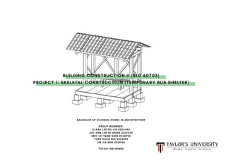
  • 1. BACHELOR OF SCIENCE (HONS) IN ARCHITECTURE GROUP MEMBERS: CLARA LEE PEI LIN 0324495 JOY ANN LIM EE HSIEN 0327592 ERIC LO YANN SHIN 0324922 YUEN XUAN HUI 0324292 LEE JIA MIN 0324126 TUTOR: MR EDWIN BUILDING CONSTRUCTION II (BLD 60703) PROJECT 1: SKELETAL CONSTRUCTION (TEMPORARY BUS SHELTER)
  • 2. 03 06 24 04 07 26 05 10 27 14 28 20 29 21 30 CONTENTS 1.0 Introduction 3.0 Orthographic Drawings 6.3 Loads and Forces 6.2 Timber Skeletal Frame Construction 9.0 Reference 2.0 Design Considerations 4.0 Construction Process 6.4 Materiality 2.1 Design Development 5.0 Construction Details 6.5 Load Test 2.2 Final Design 7.0 Renderings 6.0 Design Analysis 8.0 Conclusion
  • 3. 1.0INTRODUCTION A bus shelter is known as a designated place where bus- es stop for passengers to board or alight from a bus. It is a struc- ture constructed at a bus stop, to provide seating and protec- tion from the weather for the convenience of waiting passengers. In this assignment, we were given a task to design and construct a temporary bus shelter for 5 to 6 people on a scale of 1:5. The bus shelter model has a maximum height of 600mm and a maximum base of 400mm x 800mm. In order to create a stable and strong structure, we have to have a clear understanding of skeletal frames and its joints. Before constructing the bus shelter, we had to chose two forms to combine into a design form to base on. Initially, we chose a hexagonal prism and a cuboid to create the bus shelter design. But after some discussion and trial and error through model making, it was amended to a pentagonal prism to provide stability and strength to support the loads and forces exerted on the shelter. 03
  • 4. The choice of materials must be waterproof and be able to withstand the humid and tropical climate that we have in Malaysia. The design should accomodate to the heavy rainfall and the strong solar radiation. Weather Resistant Stable Ergonomics Suitability of Materials The construction of the shelter has to be able to resists lateral and horizontal forces without collapsing to dead or live loads or uplifting due to wind loads. The shelter has to be built according to human anthropometry for human comfort and convenience of user. It should provide sufficient space for maximum capacity of users. Materials chosen need to be appropriate and have high durability and strength to efficiently support the structure. It should be locally available and eco-friendly. 2.0 DESIGN CONSIDERATIONS 04
  • 5. 2.1 DESIGN DEVELOPMENT The initial design only had a seating and an X-bracing to support lateral and horizontal forces. The overall design did not fuly apply all the struc- tural components required from the brief and was deemed unsuitable as it had a weak stability. Mock Up 1 Mock Up 2 Mock Up 3 The idea of the angled roof was maintained with addition of extra beams, columns and X-bracing to increase stability and safety of the structure. The structure however was quite long and required additional beams and columns for support. The X-bracing was retained in the next model although reduced to increase stability. A roof beam was added to suport the load of the cantilevered pitched roof. 05
  • 6. The finalized design is a timber skeletal frame structure with minor modifications from the previous mock up such as adding more structural components and adjusting the dimensions of rafters, bearer and joist. 2.2 FINAL DESIGN 06
  • 7. 3000 2000 250 400 3.0 ORTHOGRAPHIC DRAWINGS 07 Foundation Plan Scale 1:25 Floor Plan Scale 1:25 3900 2000 415150 150
  • 9. 3650 3000 25500 093.0 ORTHOGRAPHIC DRAWINGS Front Elevation Scale 1:25 Side Elevation Scale 1:25
  • 10. 4.0 CONSTRUCTION PROCESS 10 Preparation of Materials Footing Each timber component is measured and marked to the correct dimensions to be cut. A timber block is used to represent the concrete footing in this 1:5 model due to sustainability issues and con- venience as requested by our tutor. The wood is cut according to the marked dimensions with help assisted by workers at the workshop for safety and accuracy reasons. Gum is applied to attached the timber pad footing and the stump. The ends of the wood are polishedandsandedtosmoothen out the rough edges. The footing is further strengthen by nailing it. The columns, beams, rafters, joists, stump and footings. The complete pad footing and stump.
  • 11. 4.0 CONSTRUCTION PROCESS 11 Base Frame & Flooring Beams & Columns Post anchor brackets are screwed down unto the foot- ing and then screwed unto the ground beams or column. The timber beams and columns are measured, marked and cut to create half lap joints. The spacing for the joists are marked and then secured to the beam using an L bracket. Nuts and bolts of suitable size are prepared to secure the beam and column together. The position of the joist beneath is marked on the floor panels to be accurately nailed. A drill is used to create holes for the nut and bolt. The floor panels are nailed to the joist and beam. The lap joint is then fixed tightly with nut and bolt in the intersection of the beams and columns.
  • 12. 4.0 CONSTRUCTION PROCESS 12 Roofing The rafters are cut to form a birdsmouth joint to connect with the roof beam. The rafters are placed with the specific spacings and then nailed to ensure stability. A drill is used to screw in the battens to the rafters. The roof rafters, beams and battens. Seating The seating panels are nailed to the noggins. Timber blocks are nailed together to form a U shaped column for the seats. The bracings are nailed to the columns. The centre of the cross bracing is tighten using nuts and bolts. Bracing
  • 13. 4.0 CONSTRUCTION PROCESS 13 Roofing Two corrugated steel sheet is placed with a metal ridge cap placed at the centre of both sheets to prevent leakage of rainwater. The sheets are connected through rivets. Theexcessridgecapostrimmed to fit the bus shelter. The final model of the temporary bus shelter
  • 14. 5.0 CONSTRUCTION DETAILS 14 Details Foundation Plan Connections Concrete Pad Footing b) Pad footing to ground beams Post anchor brackets are also used to connect the footing to the ground beams. a) Pad footing to columns Post anchor brackets secured with nuts and bolts are used to strengthen the connection between the timber column and con- crete footing. Footing dimensions: 400 x 400 x 200, 250 x 250 x 300 Column Column Post anchor bracket Post anchor bracket Footing Footing
  • 15. 5.0 CONSTRUCTION DETAILS 15 Details Foundation Plan Connections Timber Base Frame b) Ground beam to column Rebated butt joint is used to connect the ground beam to column and then tightly secured with an anchor bracket and nuts and bolts to further strengthen the joint. a) Joist to ground beam Timber joist are cut separately to be flushed and connected to the ground beams using an L-bracket secured with nuts and bolts. Front & back joist dimensions: 50 x 125 x 887.5 Joist spacing: 600 Rim joist dimensions:50 x 125 x 775 Front ground beam dimensions: 75 x 200 x 3000 Middle and back ground beam: 75 x 200 x 2700 Joist Column L- bracket Post anchor bracket Ground Beam Ground beam
  • 16. 5.0 CONSTRUCTION DETAILS 16 Details Floor Plan Connections Timber Flooring a) Floor panel to ground beam/joist Each timber floor panel is secured by nailing it to each floor joist underneath. The floor panel located at the ends are also nailed to the ground beam. Floor decking dimension: 25 x 2000 x 3000 Floor panel dimension:25 x 100 x 3000 Timber planks Ground Beam Nails
  • 17. 5.0 CONSTRUCTION DETAILS 17 Details Perspective Connections Timber Seat b) Seat panel to noggin The ends of the seat panels are secured by nailing it down to the noggin between the two columns. a) Seat Column to flooring Seat columns are fasten to the floor decking with L brackets. Seat dimension:25 x 415 x 3000 Seat panel dimension:25 x 100 x 3000 Seat Column dimension:100 x 100 x 475 Nails Flooring Noggins Seat Column L-bracket Seat Panels
  • 18. 5.0 CONSTRUCTION DETAILS 18 Details Perspective Connections Timber Column b) Front column to tie beam Half lap joint is used to connect the centre of the tie beams to the front column and is secured with nuts and bolts. a) Back column to tie beam Rebated butt joint is used to allow the tie beams to rest flushed on the back column and is fastened using nuts and bolts. Front column dimension: 150 x 150 x 2900 Back column dimension:150 x 150 x 2560 Back Column Front Column Roof Beam Tie Beam
  • 19. 5.0 CONSTRUCTION DETAILS 19 Details Perspective Connections Timber Roof b) Rafter to beam The rafter is connected to the roof beams by using a birdsmouth joint. a)Tie beam to roof beam The roof beam is rested on top of the tie beam and fasten using L brackets. Roof beam dimension: 75 x 125 x 3000 Tie beam dimension: 75 x 125 x 2000 Ridge beam dimension: 75 x 175 x 3000 Rafter dimension: 50 x 75 x 1065 Batten dimension: 50 x 75 x 3900 Column L bracket Rafter Beam Roof Beam
  • 20. 6.0 DESIGN ANALYSIS The long bench allows more people to sit while waiting for the bus. The absence of walls maximises the ventilation in the bus shelter and views towards the surround- ings. This prevents from storing up and creates a comfortable space of the bus shelter. A 2-way roof allows more sheltered space suit- able for tropical weather. The parallel valley troughs of the corrugated metal sheets help to direct water flow in one direction. Overhang on both front and back aids in the sun shading function of the bus shelter. The whole structure is elevated above the ground to prevent moisture from the ground to have di- rect contact with the timber structure. 20 Humidity Space Rain Flow Sun Shading Ventilation
  • 21. 6.1 TIMBER SKELETAL FRAME CONSTRUCTION Members of Bus Shelter 21 Corrugated steel sheet roof Timber ground beam Timber rafter Timber batten Timber roof beam Timber tie beam Timber column Timber X bracing Timber K bracing Timber floor decking Timber rim joist Timber joist Timber noggin Concrete pad foundation Concrete stump
  • 22. 6.1 TIMBER SKELETAL FRAME CONSTRUCTION Horizontal and Vertical Members Skeletal frame construction is the internal supporting structure which consists of horizontal and vertical members to support the floor, roof and wall in a structure. The structure had to transfer vertical forces such as dead loads, live loads, rain and gravity through the members of the frame to a suitable founda- tion as well as withstand lateral forces such as earthquake and wind. Vertical members: column, rafter, seat column Structural element that transmits, through compression the weight of the structure above to other structural elements Horizontal members: ridge beam, purlin, tie beam, roof beam, joist, bearer, seat beam Structural element that carries loads transverse to its longitudinal axis by its internal resistances to bending. 22
  • 23. 6.1 TIMBER SKELETAL FRAME CONSTRUCTION Timber Bracing Systems Structure require braces to resists sway movement from lateral forces that is caused by strong winds and disasters such as earthquakes. Concentric braced frames are used where both ends of the brace join at the end points of the other framing members to form a stiff frame. This type of bracing provides the same strength in both directions. 23 Cross BracingK Bracing
  • 24. 6.2 LOADS AND FORCES Load System: Two Way Slab System The structure’s load transfer mechanism channels the load to the ground in two directions. This is due to the ratio of the longer ground beam span to shorter joist is less than 2. Longer ground beam span = 3 Shorter joist span 2 = 1.5 > 2 24
  • 25. 6.2 LOADS AND FORCES a) Dead Loads • Dead loads are static forces that act vertically downward on the structure caused by the permanent weight of the elements and com- ponents. • A permanent force that remains throughout the lifespan of the struc- ture. b) Live Loads • Live loads are moving or moveable loads on a structure resulting on a struc- ture from occupancy and rainfall • The intensity of the live loads varies depending on the usage and capacity. • The pitched angle roof prevents the accumulation of rain on the roof, thus increase the ability to withstand weather c) Wind Load • Open structure allows even distribution of wind force into the bus shelter, causing balanced air pressure above and below the roof, reducing uplift force on the roof Load Systems: External Forces 25
  • 26. 6.2 MATERIALITY Timber Meranti Wood - Columns, beams, rafters, battens, floor joist, seating Resak Wood - Stump Plywood - Flooring Advantages: • Sustainable and reusable • High in durability and strength • Good insulator • Cost efficient Disadvantages • If not treated, it has a low fire resistance and is susceptible to shrinking, swelling and disolouration In-situ Concrete Pad footing Advantages: • High compressive strength • Good weather resistance • Long-lasting and durable • Non- combustible Disadvantages • Relatively low tensile strength Corrugated Steel Sheet Roofing Advantages: • High durability and long- lasting • Provides protection against UV rays • Albe to withstand wind loads • Maximum shedding of rain and minimal leakage Disadvantages • May cause noise during rainfall • Susceptible to denting 26
  • 27. 6.3 LOAD TEST 27 Roof Test subject: 500ml water bottle (0.5kg each) Unit: 6 water bottles Total load: 3kg Representation: Live loads that are imposed on the roof, such as rain. Test Result: Successful. The structure is able to withstand the live loads imposed on it. Bench Test subject: Book A (3 kg each), Book B (1.2kg each) Unit: 1 Book A, 2 Book B Total load: 5.4 kg Representation: Live Loads imposed by peo- ple when they sit on the bench. Test Result: Successful. The structure is able to withstand the live loads imposed on it. Timber Decking Testsubject: 500mlwaterbottle(0.5kgeach), Book A (3 kg each), Book B (1.2kg each) Unit: 6 water bottles, 1 Book A, 2 Book b Total load: 9.4kg Representation: Live Loads imposed on the timber floor decking Test Result: Successful. The structure is able to withstand the live loads imposed on it.
  • 28. 7.0 RENDERING OF MODEL 28
  • 29. 8.0CONCLUSION In conclusion, this exploration has allowed us to apply the knowl- edge of skeletal construction in a practical design of a bus shelter. During the design development, it was crucial to find a balance between design and practical constructability. Through detailed and thorough research on various structural joints, appropriate connections were chosen to ensure stability and withstand the applied loads and forces. The importance of the choice of building materials were also highlighted in order to maintain good stability. Over- all, our temporary bus shelter was design and constructed to accom- modate the Malaysian weather and provide users maximum comfort. 29
  • 30. 9.0REFERENCES Woodworking joints. (2017). Craftsmanspace.com. Retrieved 7 October 2017, from http://www.craftsmanspace.com/knowledge/woodworking-joints.html Ching, F., & Adams, C. (2001). Building construction illustrated (3rd ed.). Canada: John Wiley & Sons, Inc. Baylor, C. (2017). 13 Methods of Wood Joinery Every Woodworker Should Know. The Spruce. Retrieved 7 October 2017, from https://www.thespruce.com/wood-join- ery-types-3536631 Lyons, A. (2007). Materials for architects and builders (3rd ed.). London: Routledge, Taylor & Francis Group. frames. (2012). Construction-greatopportunity.blogspot.my. Retrieved 10 October 2017, from http://construction-greatopportunity.blogspot.my/2012/03/frames. html Difference between One Way Slab and Two Way Slab |. (2017). CIVIL READ. Re- trieved 11 October 2017, from https://civilread.com/differences-one-way-slab- two-way-slab/ Timber structures Seismic Resilience. (2013). Seismicresilience.org.nz. Retrieved 11 October 2017, from http://www.seismicresilience.org.nz/topics/superstructure/ commercial-buildings/timber-structures/ What is Cross Bracing?. (2017). wiseGEEK. Retrieved 11 October 2017, from http:// www.wisegeek.com/what-is-cross-bracing.htm Braced frames Seismic Resilience. (2017). Seismicresilience.org.nz. Retrieved 12 October 2017, from http://www.seismicresilience.org.nz/topics/superstructure/ seismic-design-concepts/braced-frames/ 30