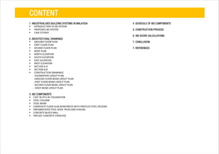
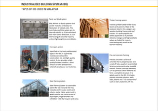
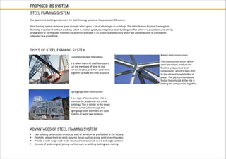
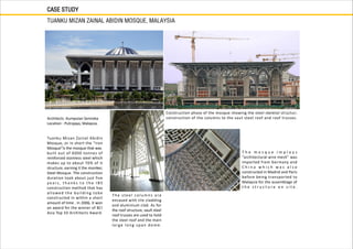
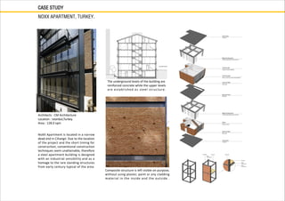
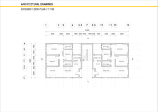
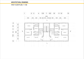
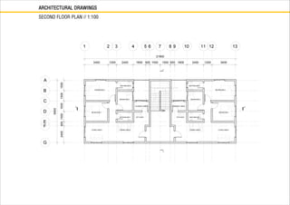
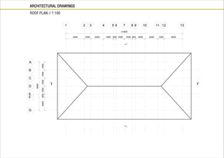
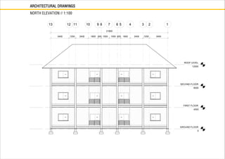
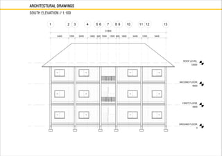
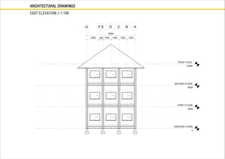
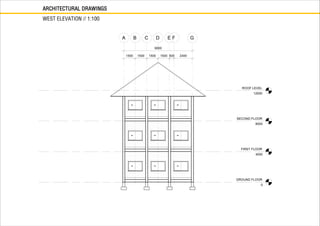
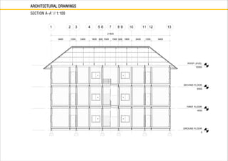
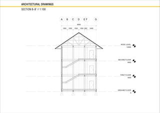
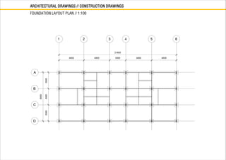
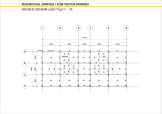
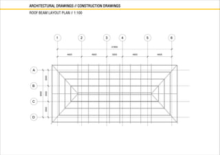
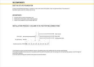
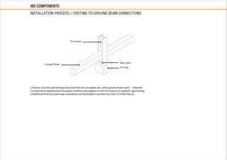
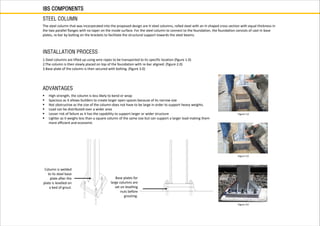
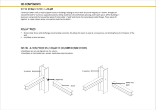
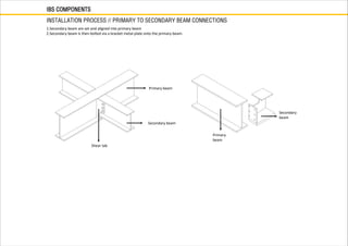
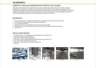
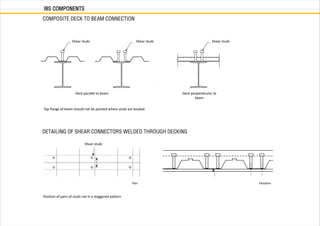
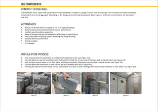
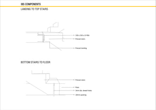
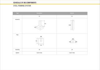
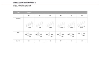
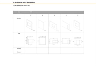
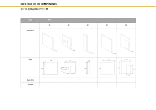
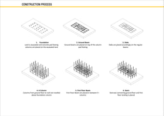
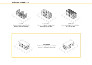
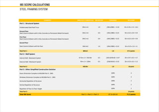
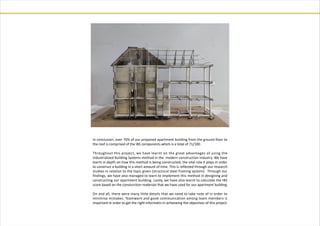
1. BUILDING TECHNOLOGY 1
INDUSTRIALISED BUILDING SYSTEMS
CHOW SU LING
LIM PEIDI
NG LEK YUEN
NG PUI YAN
SARAH ESA
0325020
0324272
0324010
0324785
0324805
TUTOR : MR RIZAL
2. CONTENT
1. INDUSTRIALISED BUILDING SYSTEMS IN MALAYSIA
INTRODUCTION TO IBS SYSTEM
PROPOSED IBS SYSTEM
CASE STUDIES
2. ARCHITECTURAL DRAWINGS
GROUND FLOOR PLAN
FIRST FLOOR PLAN
SECOND FLOOR PLAN
ROOF PLAN
NORTH ELEVATION
SOUTH ELEVATION
EAST ELEVATION
WEST ELEVATION
SECTION A-A'
SECTION B-B'
CONSTRUCTION DRAWINGS
- FOUNDATION LAYOUT PLAN
- GROUND FLOOR BEAM LAYOUT PLAN
- FIRST FLOOR BEAM LAYOUT PLAN
- SECOND FLOOR BEAM LAYOUT PLAN
- ROOF BEAM LAYOUT PLAN
3. IBS COMPONENTS
CAST IN-SITU RC FOUNDATION
STEEL COLUMN
STEEL BEAM
COMPOSITE FLOOR SLAB REINFORCED WITH PROFILED STEEL DECKING
PREFABRICATED STEEL ROOF TRUSS AND PURLINS
CONCRETE BLOCK WALL
PRECAST CONCRETE STAIRCASE
4. SCHEDULE OF IBS COMPONENTS
5. CONSTRUCTION PROCESS
6. IBS SCORE CALCULATIONS
7. CONCLUSION
7. REFERENCES
4. INDUSTRIALISED BUILDING SYSTEM (IBS)
WHAT IS INDUSTRIALISED BUILDING SYSTEM?
An Industrialised Building System refers to a technique of construction that is used broadly by the industry and government in Malaysia to represent the
adoption of industrialisation and the use of prefabrication of components in building construction. In IBS, the components are manufactured in a
controlled environment. These controlled environment can be either onsite or offsite where it is used to store, transport, position and assemble building
components into construction works.
The building components in the IBS system includes walls, floors, beams, and staircases.
HISTORY OF IBS
1624
Introducing of
the IBS in the
E u r o p e a n
countries and
t h e U n i t e d
S t a t e s
1963
I B S w a s i n i t i a t e d i n
M a l a y s i a w h e n t h e
Ministry of Housing and
Local Government made
visits to several European
municipalities with the
objective of assessing their
housing development
plans. It was to explore the
t h e c o n c e p t s o f
development in these
countries in further detail.
1964
Malaysia government launched a
project to test the efficiency of the IBS.
The key objectives looking to be fulfilled
include the acceleration as well as the
increase of affordable housing of
substantial quality here in Malaysia.
Present
As reported, there are 21 different
manufacturers and suppliers that are
promoting their components in
Malaysia. An IBS centre has also been
established in Jalan Chan Sow Lin,
Cheras, Kuala Lumpur who are
responsible for implementing strategies
and introducing breakthroughs in the
I B S te c h n o l o g y to i m p rove i t s
performance and quality in the
construction industry as well as to
reduce dependencies on foreign labour.
ADVANTAGES OF IBS METHOD
Attaining better quality and productivity
Reducing risk related to safety and health
Alleviating issues for skilled workers and dependency for manual foreign labour
Reduce overall cost of construction The building components in the IBS system includes walls, floors, beams, and staircases.
5. INDUSTRIALISED BUILDING SYSTEM (IBS)
TYPES OF IBS USED IN MALAYSIA
Pre-cast concrete framing
Precast concrete is a form of
concrete that is prepared, cast and
cured off-site, usually in a controlled
factory environment using reusable
moulds. Precast concrete elements
can be joined to other elements to
form a complete structure. It is
widely used in the IBS. It includes
precast concrete columns, walls,
slabs, beams and “3-D components”
such as stairs, balconies, lift etc.
Formwork system
Identified as the least prefabricated
types in the IBS. It is generally
involves concrete at the
construction site and high quality
control. It also provides a high
quality finishes in within a short
amount of time and demand
relatively less labour and materials.
Steel framing system
Steel framing system is sustainable
option for low-rise and mid-rise,
Includes steel trusses, beams and
column portal frame system and is
widely used in the construction of
skyscrapers, large factories and
exhibition halls that require wide area.
Panel and block system
May defines as those systems that
use 3D modules (or boxes) for
fabrication of habitat units. The
main feature of this system are its
internal stability as it can withstand
load from varius directions. It is an
interlocking of concrete masonry
units or lightweight concrete blocks.
Timber framing system
Involves prefabricated timber truss
beams and columns. Most of the
products listed in this category are
wooden building frames and roof
trusses. It is quite popular and
widely applicable as it provides
attractive designs and high aesthetic
values as chalets for resorts,
contributing very much to the
tourism industry.
6. INDUSTRIALISED BUILDING SYSTEM (IBS)
IBS WORK FRAME
1. Design considerations
Recognizing and analyzing the
design, determining the
conditions, considering the
productivity and optimizing
the layout
2. Manufacturing
Tally with the standar
d i m e n s i o n s o f t h e
manufactured components.
The manufacturing process
are based on the scedule
and construction process.
3. Delivering
The manufactured components
are then shifted to the site for
assemblage. At the preliminary
stage of production, the size of
the components must take into
account so that the components
can fit into the truck efficiently.
4. Assembly
Once the components
arrived on site, they are
then assembled quickly
to reduce time wastage.
These components are
assembled together into
a complete unit.
5. Completion
Finis h e s o f t h e b u i l d i n g
happens at this stage. The
facade of the building is
painted and coated to improve
the aesthetic quality of the
building.
7. PROPOSED IBS SYSTEM
STEEL FRAMING SYSTEM
TYPES OF STEEL FRAMING SYSTEM
Our apartment building implement the steel framing system as the proposed IBS system.
Steel framing system immense great strength which gives a lot of advantages to buildings. The other feature for steel framing is its
flexibility. It can bend without cracking, which is another great advantage as a steel building can flex when it is pushed on one side by
strong wind or earthquake. Another characteristics of steel is its plasticity and ductility which will avoid the steel to crack when
subjected to a great force.
Conventional steel fabrication
It is when teams of steel fabricators
cut the members of steel to the
correct lengths, and then weld them
together to make the final structure.
Botled steel construction
This construction occurs when
steel fabricators produce the
finished and painted steel
components, which is then shift
to the site and simply bolted in
place. The job is tremendously
fast as the only job at the site is
bolting the components together.
Light gauge steel construction
It is a type of construction that is
common for residential and small
buildings. This is similar to the wood
framed construction except that
light gauge steel members are used
in place of wood two-by-fours.
ADVANTAGES OF STEEL FRAMING SYSTEM
Fast building construction on site, as a lot of work can be pre-fabbed at the factory.
Flexibility allows them to resist dynamic forces such as strong wind or earthquakes.
Provide a wide range read-made structural sections such as I, C and angle sections.
Consists of wide range of joining method such as welding, bolting and riveting.
8. CASE STUDY
TUANKU MIZAN ZAINAL ABIDIN MOSQUE, MALAYSIA
Architects :Kumpulan Senireka
Location : Putrajaya, Malaysia.
Tuanku Mizan Zainal Abidin
Mosque, or in short the “Iron
Mosque”is the mosque that was
built out of 6000 tonnes of
reinforced stainless steel which
makes up to about 70% of it
structure, earning it the moniker,
Steel Mosque. The construction
duration took about just five
y e a r s , t h a n k s t o t h e I B S
construction method that has
allowed the building tobe
constructed in within a short
amount of time . In 2006, it won
an award for the winner of BCI
Asia Top 10 Architects Award.
The steel col u m n s a re
encased with tile cladding
and aluminium clad. As for
the roof structure, vault steel
roof trusses are used to hold
the steel roof and the main
large long span dome.
T h e m o s q u e i m p l o y s
“architectural wire mesh” was
imported from Germany and
C h i n a w h i c h w a s a l s o
constructed in Madrid and Paris
before being transported to
Malaysia for the assemblage of
t h e s t r u c t u r e o n s i t e .
Construction phase of the mosque showing the steel skeletal structur;
construction of the columns to the vaut steel roof and roof trusses.
9. CASE STUDY
NOXX APARTMENT, TURKEY.
Architects : CM Architecture
Location : Istanbul,Turkey.
Area : 128.0 sqm
NoXX Apartment is located in a narrow
dead end in Cihangir. Due to the location
of the project and the short timing for
construction, conventional construction
techniques seem unattainable, therefore
a steel apartment building is designed
with an industrial sensibility and as a
homage to the rare standing structures
from early century typical of the area.
The underground levels of the building are
reinforced concrete while the upper levels
are established as steel structure.
Composite structure is left visible on purpose,
without using plaster, paint or any cladding
material in the inside and the outside .
27. IBS COMPONENTS
CAST IN-SITU RC FOUNDATION
A precast spread footing foundation is utilized as it suits to the scale of the project, a low rise apartment block. The selection of
foundation system eases the mobility into the site.
Economic due to control of foundation size
Shallow form of foundation needs a little excavation
Shape can be designed to accommodate tight sites
ADVANTAGES
INSTALLATION PROCESS // COLUMN TO RC PAD FOOTING CONNECTIONS
1.The footing for precast concrete foundations requires a foundation base to be installed onto the concrete spread footing.
2.The depth and width of stone base are in accordance with the width of foundation wall, the existing site’s soil load-bearing capacity, 3.and the height of
construction materials.
4.Concrete spread footing were utilised as the precast concrete foundation.
Grout pack
Rc pad footing
Steel column
Base plate
Holding-down bolts
Reinforcement bar
28. INSTALLATION PROCESS // FOOTING TO GROUND BEAM CONNECTIONS
IBS COMPONENTS
1.Precast concrete pad footings were laid onto the excavated site, while ground beams were attached.
2.A downward displacement boundary condition was applied on the soil stratum to establish rigid footing.
3.Additional bracing system was considered and developed to prevent any form of brittle failure.
H-column
Ground Beam
Base plate
Footing
29. IBS COMPONENTS
STEEL COLUMN
The steel column that was incorporated into the proposed design are H steel columns, rolled steel with an H-shaped cross section with equal thickness in
the two parallel flanges with no taper on the inside surface. For the steel column to connect to the foundation, the foundation consists of cast-in base
plates, re-bar by bolting on the brackets to facilitate the structural support towards the steel beams.
High strength, the column is less likely to bend or wrap
Spacious as it allows builders to create larger open spaces because of its narrow size
Not obstructive as the size of the column does not have to be large in order to support heavy weights.
Load can be distributed over a wider area
Lesser risk of failure as it has the capability to support larger or wider structure
Lighter as it weighs less than a square column of the same size but can support a larger load making them
more efficient and economic
ADVANTAGES
INSTALLATION PROCESS
1.Steel columns are lifted up using wire ropes to be transported to its specific location (figure 1.0)
2.The column is then slowly placed on top of the foundation with re-bar aligned. (figure 2.0)
3.Base plate of the column is then secured with bolting. (figure 3.0)
Figure 1.0
Figure 2.0
Figure 3.0
Column is welded
to its steel base
plate after the
plate is levelled on
a bed of grout.
Base plates for
large columns are
set on levelling
nuts before
grouting.
30. IBS COMPONENTS
STEEL BEAM // STEEL I-BEAM
I-beams are often used as major support trusses in buildings, helping to ensure their structural integrity. An I-beam’s strength can
reduce the need for numerous support structures, letting builders create aesthetically-pleasing, wide-open spaces within buildings. I-
beams are comprised of a long vertical piece of metal called a “web “and shorter horizontal pieces called flanges. These pieces fit
together to create a beam whose cross section looks like the letter I.
Resists shear forces while its flanges resist bending moments; this allows the beam to excel at carrying shear and bending forces 2.in the plane of the
web.
Less likely to bend and warp
ADVANTAGES
INSTALLATION PROCESS // BEAM TO COLUMN CONNECTIONS
1.Steel beam are set and aligned into the column.
2.Steel beam is then bolded via a bracket metal plate onto the column.
H-column
Angle clip
I-beam
H-column
Metal end
plate
31. IBS COMPONENTS
INSTALLATION PROCESS // PRIMARY TO SECONDARY BEAM CONNECTIONS
1.Secondary beam are set and aligned into primary beam
2.Secondary beam is then bolted via a bracket metal plate onto the primary beam.
Secondary beam
Shear tab
Primary beam
Primary
beam
Secondary
beam
32. IBS COMPONENTS
COMPOSITE FLOOR SLAB REINFORCED WITH PROFILED STEEL DECKING
Composite steel floor deck consist of a profiled steel deck with a concrete topping. Included within the concrete is some light
reinforcement (see Figure 8.0). Indentations in the deck enable the deck and concrete to act together as a composite slab. The
reinforcement is included to control cracking, resist longitudinal shear and, in the case of fire act as tensile reinforcement. To develop
composite action between beam and concrete slab, shear studs are welded through the deck onto the top flange of the beam. A
result of two-way-acting composite floor is structurally efficient and economic to construct.
Great durability because it is resilient to weather, moisture, pest deterioration and has corrosion protection.
Excellent spanning capacities for greater strength and less deflection.
Act as a permanent formwork.
Speedy, safe and easy on-site handling due to it is produced in pre-cut lengths.
Cost reduction due to most of installation method are by hand and no heavy duty machines are required.
Fire resistance
ADVANTAGES
INSTALLATION PROCESS
1. Steel deck arrive on site in bundle then craned to different floors. (see Figure 1.0)
2. Lay steel deck sheets on supporting beam.
3. Steel deck cut away for clarity. (see Figure 2.0)
4. Shear stud connection welded through decking onto steel beam. (see Figure 3.0)
5. Place rebar on top of steel deck. (see Figure 4.0)
6. Pour cast-in-situ concrete onto steel deck. (see Figure 5.0)
7. Set it dry.
Figure 1.0 Figure 2.0 Figure 3.0 Figure 4.0 Figure 5.0
33. IBS COMPONENTS
COMPOSITE DECK TO BEAM CONNECTION
Top flange of beam should not be painted where studs are located.
Shear studs
Deck parallel to beam Deck perpendicular to
beam
DETAILING OF SHEAR CONNECTORS WELDED THROUGH DECKING
Plan Elevation
Position of pairs of studs not in a staggered pattern
Shear studsShear studs
Shear studs
34. IBS COMPONENTS
SLAB TO BEAM CONNECTION
250mm
Concrete Slab
Rebar Mesh
Shear Studs
Profiled Steel Decking
Universal Beam
SLAB TO PRIMARY AND SECONDARY BEAM CONNECTION
250mm Concrete Slab with rebar
Profiled Steel Decking
Beam Brackets
Universal Beam
35. IBS COMPONENTS
PREFABRICATED STEEL ROOF TRUSS AND PURLINS
King post steel truss is a series of triangles combine to distribute the load across each of the other members, resulting in a light
structure that is stronger than the sum of the strength of its individual components.
Fire-resistant because it insulated against sparks and prevent fire spreading to other building parts.
Long-lasting and durable
Low maintenance because it will not crack, shrink, or wrap under the effects of humidity, sunlight, or other weather problems.
Light-Weight
Fast Installation and allow quicker, less expensive installation
Environmentally friendly, recyclable and has high resale value
ADVANTAGES
INSTALLATION PROCESS
1. Steel truss are prefabricated in factory then transported to site. (see Figure 1.0)
2. During construction, trusses are craned and place on supporting beams. (see Figure 2.0)
3. Connection of truss to beam is locked using bolt and nut.
4. Purlin is screw on trusses (see Figure 3.0)
5. Place underlayment material such as aluminium netting, rock wool insulation and reflective foil insulation.
6. Cover underlayment with galvalume metal roof panels then screw to securely fix the roof. (see Figure 4.0)
Figure 1.0 Figure 2.0 Figure 3.0 Figure 4.0
36. IBS COMPONENTS
HIP ROOF CONNECTION
Welded
connection
Pre-fabricated Steel Truss
CEE PURLIN TO TRUSS CONNECTION
Roof sheathing
Cee Purlin
Screw each purlin to connect to steel roof truss
Pre-fabricated roof truss
38. Concrete block wall is a wall made up of individual concrete blocks arranged in a proper manner. Each block are pre-cast in moulds and made of concrete
comprised of cement and aggregate. Depending on the design parameters and standards set by an engineer for the concrete structure, the block sizes
may vary.
Figure 1.0
Robust and durable which is suitable to use in all types of building.
Good Rw values and provides excellent acoustic performance.
Excellent sound insulation properties.
Range of strength options are available for wide range of specifications.
Easy to decorate in drylining, plaster, rendering and fixings finishing.
Excellent thermal performance
Termite resistant
Fire resistant
1. Each concrete block are prefinished in factory then transported to site. (see Figure 1.0)
2. Concrete blocks are lay out in stretcher bond method with a chalk line on each side of the block wall as reference line. (see Figure 2.0)
3. High strength cement mortar is mix then butter on the concrete block. Any excess mortar will be trim and remove. (see Figure 3.0)
4. Concrete block wall connection to steel column are lay in between each brick. (Figure x.x)
5. Finishing for exposed concrete block wall are painted with two coats of alkali resisting primer that provide resistance to alkali attack. (see Figure 4.0)
Figure 2.0 Figure 3.0 Figure 4.0
IBS COMPONENTS
CONCRETE BLOCK WALL
ADVANTAGES
INSTALLATION PROCESS
39. Concrete block tie channel welded to steel column
Concrete block tie channel welded to steel column
Concrete block
Concrete block
Connection lay together with cement mortar layer
I beam
I beam
IBS COMPONENTS
WALL TO COLUMN CONNECTIONS
40. 340mm x 215mm Concrete Blocks Wall
High strength cement mortar
L Clip Angle at the side of wall (apply on
both sides of wall if wall are in the middle)
Composite Floor Slab Reinforced with Profiled Steel Decking
I Beam
Stretcher Bond
Concave
IBS COMPONENTS
WALL TO SLAB CONNECTIONS
CONCRETE BLOCK PATTERN CEMENT MORTAR PROFILE
41. IBS COMPONENTS
PRECAST CONCRETE STAIRCASE
Precast concrete stair is made up of reinforced concrete and is one of the best option to eliminate the trouble of adjusting the
number of steps, rise, run and width of each stair flight. They provide safe, solid and instant vertical access during construction and a
safe base for attractive finishes during the completion phase.
The monolithic top and bottom landings eliminate the need of forming landings on site.
Advanced mechanical connection, speeds the installation process along with eliminating the need of propping.
Designed and manufactured to any specific floor haight and application.
Durable and maintenance free.
Better quality control
ADVANTAGES
INSTALLATION PROCESS
1. Stair is manufactured at a factory.
2. Precast landing is secured to the walls with brackets.
3. Precast stair is then secured to the landing with RSA (rolled steel angle)
150 x 150 x 12 RSA
Precast landing
Structural shim packers
Concrete wall
LANDING TO WALL
42. IBS COMPONENTS
BOTTOM STAIRS TO FLOOR
LANDING TO TOP STAIRS
Precast stairs
150 x 150 x 12 RSA
Precast landing
Precast stairs
Floor
3mm dia. dowel holes
10mm packing
54. 1. Foundation
Land is excavated and concrete pad footing
columns are placed on the excavated land
2. Ground Beam
Ground beams are placed on top of the column
pad footing
3. Slabs
Slabs are placed accordingly on the regular
beams
4. H Column
Columns from ground floor to roof are installed
above foundation column
5. First Floor Beam
First Floor Beam are placed in between H -
columns
6. Stairs
Staircase connecting ground floor and first
floor landing is placed
CONSTRUCTION PROCESS
55. 7. Walls
Blockwork walls are installed after the
structural frame have completed
8. Upper Floors
Step 3 to 7 is repeated for upper floors
construction with roof beam
3. Roof Structure
Roof trusses and purlins are installed on
top of the roof beam
10. Completion
Roof layering are placed on top of the roof
structure to complete the construction
CONSTRUCTION PROCESS
57. IBS SCORE CALCULATIONS
STEEL FRAMING SYSTEM
ELEMENTS AREA (m2) / LENGTH (m) IBS FACTOR COVERAGE IBS SCORE
Part 1 : Structural System
Prefabricated Steel Roof Truss
Ground Floor
Steel Column & Beam with In-Situ Concrete on Permanent Metal Formwork
First Floor
Steel Column & Beam with In-Situ Concrete on Permanent Metal Formwork
Second Floor
Steel Column & Beam with No Floor
296.4 m2
196.2 m2
196.2 m2
196.2m2
1.0
0.9
0.9
1.0
(296.4/885) = 0.33
(196.2/885) = 0.22
(196.2/885) = 0.22
(196.2/885) = 0.22
50 x 0.33 x 1.0 = 16.5
50 x 0.22 x 0.9 = 9.9
50 x 0.22 x 1.0 = 11
Total Part 1 885m2 1.0 47.3 points
Part 2 : Wall System
Internal Wall : Blockwork System
External Wall : Blockwork System
67.6m x 3 = 202.8m
76m x 3 = 228m
0.5
0.5
(202.8/430.8) = 0.47
(228/430.8) = 0.53
20 x 0.47 x 0.5 = 4.7
20 x 0.53 x 0.5 = 5.3
Total Part 2 430.8m 1.0 10 point
Part 3 : Other Simplified Construction Solution
Doors Dimension Complies to MS1064 Part 4 : 2001
Windows Dimension Complies to MS1064 Part 5 : 2001
Horizontal Repetition of Structure
Vertical Repetition of Structure
Repetition of Floor to Floor Height
100%
100%
100%
100%
100%
4
4
2
2
2
Total Part 3 14 points
Total IBS Score Part 1 + Part 2 + Part 3 47.3+10+14 71.3 points
59. In conclusion, over 70% of our proposed apartment building from the ground floor to
the roof is comprised of the IBS components which is a total of 71/100.
Throughout this project, we have learnt on the great advantages of using the
Industrialised Building Systems method in the modern construction industry. We have
learnt in depth on how this method is being constructed, the vital role it plays in order
to construct a building in a short amount of time. This is reflected through our research
studies in relation to the topic given (structural steel framing system). Through our
findings, we have also managed to learn to implement this method in designing and
constructing our apartment building. Lastly, we have also learnt to calculate the IBS
score based on the consturction materials that we have used for our apartment building.
On and all, there were many little details that we need to take note of in order to
minimise mistakes. Teamwork and good communication among team members is
important in order to get the right informatin in achieveing the objectives of this project.
60. REFERENCES
(n.d.). Retrieved from
https://ieeexplore.ieee.org/document/6226077
15, N. (2013, March 31). Design Considerations. Retrieved from
https://www.machinedesign.com/basics-design/design-considerations
And Floor Deck - Ideal Roofing, Idéal Revêtement. (n.d.). Retrieved October 1, 2018, from http://www.idealroofing.ca/english_us/pdf/technical/CSSBI-
Steel_Roof_Deck__Floor_Deck.pdf
C. (n.d.). Technical Images. Retrieved from
http://www.creaghconcrete.co.uk/precast-stairs-and-landings/technical-images.html?p=270
Ching, D. K. (n.d.). BUILDING CONSTRUCTION ILLUSTRATED(5th ed.). WILEY.
HALFEN Brick Tie Systems. (n.d.). Retrieved October 10, 2018, from
https://m.halfen.com/en/1829/products/?node=759
D. (n.d.). Typical steel connections. Retrieved from
https://www.engr.mun.ca/~adluri/courses/steel/ppt files1/Topic -Connections -typical joints.pdf
Designing Buildings Wiki Share your construction industry knowledge www.designingbuildings.co.uk. (n.d.). Retrieved from
https://www.designingbuildings.co.uk/wiki/Precast_concrete
DSTRUCTURE II BDC202 MASJID BESI,PUTRAJAYA. PN MAZLINA. (n.d.). Retrieved from
https://prezi.com/xprgcmvhi7ot/dstructure-ii-bdc202-masjid-besiputrajaya-pn-mazlina/
E. (2013, May 20). Installation of steel column. Retrieved from
https://www.youtube.com/watch?v=B9ptF_w3GDQ
Masonry Detailing Series. (n.d.). Retrieved October 7, 2018, from
http://imiweb.org/masonry-detailing-series/
NoXX Apartment / CM Architecture. (2015, February 03). Retrieved from
https://www.archdaily.com/593084/noxx-apartment-cm-architecture
Ogden, R. G., & Henley, R. (1996). CONNECTIONS BETWEEN STEEL AND OTHER MATERIALS. Retrieved October 7, 2018, from
https://www.steelconstruction.info/File:SCI_P102.pdf?internal_link.
61. REFERENCES
Rackham, J. W., Couchman, G. H., & Hicks, S. J. (n.d.). Composite Slabs and Beams using Steel Decking: Best Practice for Design and Construction (Revised Edition). Retrieved
October 1, 2018, from
https://www.steelconstruction.info/images/b/b8/SCI_P300.pdf.
Structural Steel Framing. (n.d.). Retrieved from
https://www.buildusingsteel.org/build-using-steel/structural-steel-framing
WHAT IS "INDUSTRIALIZED BUILDING SYSTEM" (IBS). (n.d.). Retrieved from
https://www.linkedin.com/pulse/what-industrialized-building-system-ibs-tunku-ariff