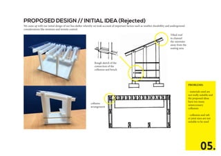
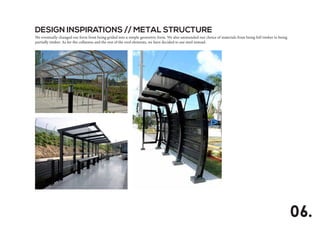
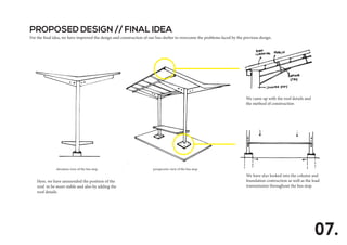
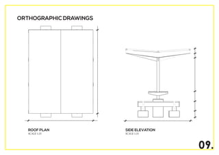
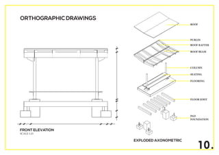
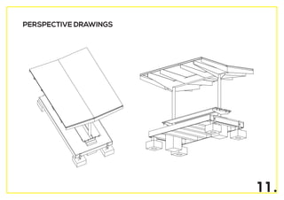
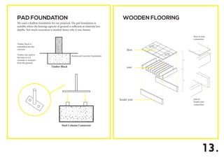
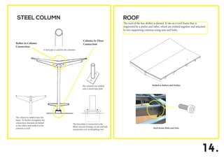
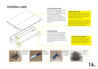
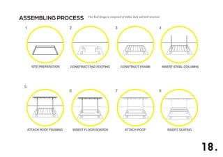
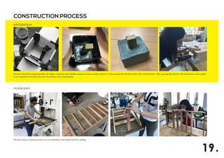
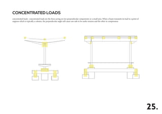
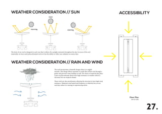
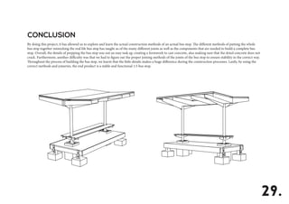
TAYLOR’S UNIVERSITY
SCHOOL OF ARCHITECTURE, BUILDING & DESIGN
BUILDING CONSTRUCTION II (BLD 60703)
PROJECT ONE: TEMPORARY BUS SHELTER
NG LEK YUEN
NG PUI YAN
SARAH BINTI MOHAMED ESA
MELISA BINTI FAISAL
ARINA NADIA BINTI FARID
0324010
0324785
0324805
0325983
0324105
SKELETAL
CONSTRUCTION.
INTRODUCTION
SKELETAL STRUCTURES
A skeletal structure is a skeletal frame used to resist vertical
and lateral forces. It works alongside the foundation, providing
strength and stability for the structure. The framing transfers all
load gravity, uplift, and lateral loads to the foundation; by
transferring loads from structural elements to the foundation,
and then to the ground. For this project, in a group of six, we are
required to design and construct a temporary bus shelter in a 1:5
scale as well as perform load-testing, to demonstrate our
understanding on how a skeletal structure reacts with load, and
skeletal construction as a design solution. Our bus shelter was
constructed using a mix of steel and timber as the materials. The
floor is covered by timber decking; and the framing is made by
steel.
01.
TABLE OF CONTENT
01INTRODUCTION
02TABLE OF CONTENT
03DESIGN PROCESS
- Inspiration and Case Studies
- Proposed Designs
08TECHNICAL
DRAWINGS
12DETAILS AND
JOINTS
15MATERIAL
SELECTION
17CONSTRUCTION
PROCESS
- Assembling process
- Construction process
23FORCE
ANALYSIS
26WEATHER
CONSIDERATION
AND
ACCESSIBILITY
02.
28CONCLUSION
30REFERENCES
DESIGN
PROCESS
Design Inspirations -
Proposed Designs -
03.
DESIGN INSPIRATIONS // TIMBER STRUCTURE
Our initial ideas were to design the bus shelter by using grids formation as we found the form interesting to explore on in terms of construction. We have
looked into several design inspirations and analysed their construction details with emphasis on joint connection methods.
Timber joint connections inspration
04.
PROBLEMS:
- materials used are
not really suitable and
the proposed ideas
have too many
unneccessary
collumns
- collumns and raft-
er joint sizes are not
suitable to be used
PROPOSED DESIGN // INITIAL IDEA (Rejected)
We came up with our initial design of our bus shelter whereby we took account of important factors such as weather durabillity and underground
considerations like moisture and termite control.
05.
Rough sketch of the
connection of the
collumns and bench
Tilted roof
to channel
the rainwater
away from the
seating area.
collumn
arrangement
DESIGN INSPIRATIONS // METAL STRUCTURE
We eventually changed our form from being grided into a simple geometric form. We also ammended our choice of materials from being full timber to being
partially timber. As for the collumns and the rest of the roof elements, we have decided to use steel instead.
06.
PROPOSED DESIGN // FINAL IDEA
For the final idea, we have improved the design and construction of our bus shelter to overcome the problems faced by the previous design.
07.
Here, we have ammended the position of the
roof to be more stable and also by adding the
roof details.
elevation view of the bus stop perspective view of the bus stop
We came up with the roof details and
the method of construction
We have also looked into the column and
foundation contruction as well as the load
transmission throughout the bus stop.
TECHNICAL
DRAWINGS
08.
09.
ROOF PLAN
SCALE 1:25
SIDE ELEVATION
SCALE 1:25
ORTHOGRAPHIC DRAWINGS
10.
FRONT ELEVATION
SCALE 1:25
ORTHOGRAPHIC DRAWINGS
EXPLODED AXONOMETRIC
ROOF
PURLIN
ROOF RAFTER
ROOF BEAM
COLUMN
SEATING
FLOORING
FLOOR JOIST
PAD
FOUNDATION
1 1 .
PERSPECTIVE DRAWINGS
DETAILS AND
JOINTS
12.
13.
PAD FOUNDATION
We used a shallow foundation for our proposal. The pad foundation is
suitable where the bearing capacity of ground is sufficient at relatively low
depths. Not much excavation is needed; hence why it was chosen.
WOODEN FLOORING
Reinforced Concrete Foundation
Timber Block
Steel Column Connector
Timber block is
embedded into the
concrete.
Timber was used as
the base as it is
resistant to moisture
from the ground.
floor to joist
connection
joist to
header joist
connection
floor
joist
header joist
14.
STEEL COLUMN ROOF
The roof of the bus shelter is slanted. It sits on a roof frame that is
supported by a purlin and rafter, which are welded together and attached
to two supporting columns using nuts and bolts.
A steel pipe is used for the columns
The column is welded onto the
beam. To further strengthen the
connection, brackets are bolted
to the rafters and welded to the
columns as well
The base plate is connected to the
lifted concrete footing via nut and bolt
connection is to avoid getting rust
The columns are welded
onto a metal base plate
Rafter-to Column
Connection
Column-to-Floor
Connection
Welded to Rafters and Purlins
Steel Socket Bolts and Nuts
MATERIAL
SELECTION
15.
MATERIAL USED
STEEL STRUCTURE
Steel structure is used as the framing as it
is able to withstand extreme forces or harsh
weather conditions, such as strong winds,
earthquakes, and hurricanes.
They are also unreceptive to rust and are not
affected by termites, bugs, mildew, mould
and fungi. In addition, they are more fire-re-
sistant compared to wooden frames.
TIMBER DECKING
Timber decking is used for the floor as
it is strong, durable, and biodegrada-
ble, making it suitable for temporary
structures. It is also able to withstand
high temperatures, and lasts for a very
long time. In addition, it is weather and
stain resistant.
CONCRETE FOUNDATION
A concrete pad foundation is used as
it has a high durability, adequate for
foundation use. It provides the highest
level of strength for foundations
16.
Round Head
Nails
for wooden
flooring
Round Screw
Bolts and Nuts
for connection
of wooden seat
on the metal
Brackets
for connection
of foundation to
wooden header
Flat Head Screws
for connection
of foundation to
wooden header
P0LYCARB0NATE R00f
Polycabonate roofing sheets are used
for the roof. it is a lightweight
material that has high durability, able
to withstand harsh weather
conditions without discolouring.
Because of this, it is suitable as it can
withstand the weather outdoors and
provide comfort to users by blocking
out uv rays.
CONSTRUCTION
PROCESS
17. Assembling process -
Construction process -
ASSEMBLING PROCESS
18.
Our final design is composed of timber deck and steel structure.
CONSTRUCTION PROCESS
FOUNDATION
FLOOR JOIST
19.
We have mixed the cement powder (to replace concrete) with suitable amount of water and the mixture is then poured into the formwork with reinforcement. After pouring the mixture, the foundation wall is added
to be conneted to the floor jois once the mixture dries and hardens.
The floor joists is measured and cut to be attached to the header joists by nailing.
FLOORING
COLUMN, ROOF BEAM and ROOF RAFTER
20.
Timber wood pieces were cut piece by piece and screwed into place to create the wooden flooring ; two 100 x 100 mm holes were made on the flooring to allow the column to connect to the foundation.
Roof, roof beam and raftar: Firstly we have chosen the suitable metal to be used for our bus shelter. The dimensions for each elements are measured to be cut. After the cutting process comes the installa-
tion process where we screw all the metal pieces together to form the complete structure of the roof.
COLUMN, ROOF BEAM and ROOF RAFTER
ROOFING
21.
The polycarbonate roof is screwed onto the purlin located above the rafter and roof beam.
Welding : The columns and beams are connected by welding. Once the welding is done, we spray painted the structure to make it look clean.
SEATING
FINAL PRODUCT
22.
Wooden panels are cut into two pieces of 700 x 80 mm and screwed to the column using bolts and nuts.
The overall final product of the bus stop consists of components from the foundation to the flooring, columns, rafters and roofings. All the parts are connected by welding and mostly screws, bolts and nuts to create a
stable bus stop.
FORCE
ANALYSIS
23.
24.
LOAD DISTRIBUTION
The dead load acting on the structure is transferred from the roof, column, and floor to it’s foundation. The use of polycarbonate as the roof doesn’t exert much force due
to it’s light weight as compared to the column and beam which uses steel. Live load is limited to the number of people the bus stop can shelter at any one time and the
frequency of users.
Live Load
Dead Load
CONCENTRATED LOADS
25.
concentrated loads : concentrated loads are the force acting on two perpendicular components or a small area. When a beam transmits its load to a point of
suppose which is typically a column, the perpendicular angle will cause one side to be under tension and the other in compression
WEATHER
CONSIDERATION
AND
ACCESSIBILITY
26.
morning
noon
evening
The form of our roof is designed in such way that it reflects the sunlight outwards throughout the day. In terms of the roof
materiality, we have used polycarbonated roof as it has the ability to reflect sun radiation on sunny days.
WEATHER CONSIDERATION // SUN
WEATHER CONSIDERATION // RAIN AND WIND
Floor Plan
not to scale
ACCESSIBILITY
The roof incorporates a butterfly design where it is angled
inwards. This design allows rainwater to easily flow off the roof through a
gutter and prevents water buildup as well. The choice of material also plays
a part as polycarbonate sheets have high resistance to weather which is
necessary for our tropical climate.
These roofs are also aerodynamic allowing the structure to have high wind
resistance. Malaysia’s wind speed and frequency is relatively low on nor-
mal days unless it is raining or experiencing storm.
27.
CONCLUSION
28.
By doing this project, it has allowed us to explore and learn the actual construction methods of an actual bus stop. The different methods of putting the whole
bus stop together mimicking the real life bus stop has taught us of the many different joints as well as the components that are needed to build a complete bus
stop. Overall, the details of prepping the bus stop was not an easy task eg: creating a formwork to cast concrete, also making sure that the dried concrete does not
crack. Furthermore, another difficulty was that we had to figure out the proper joining methods of the joints of the bus stop to ensure stability in the correct way.
Throughout the process of building the bus stop, we learnt that the little details makes a huge difference during the construction processes. Lastly, by using the
correct methods and joineries, the end product is a stable and functional 1:5 bus stop.
CONCLUSION
29.
REFERENCES
30.
1. Chudley, R. 2006, Construction Technology. 4th edition. Pearson
and Prentice Hall.
2. Seeley, Ivor H. 1995, Building Technology. 5th edition. Basingstoke,
Hants : MacMillan
3. Ching, Francis D.K. 1991. Building Construction Illustrated. New
York. Van Nostrand Reinhold.

Building construction 02

  • 1.
    TAYLOR’S UNIVERSITY SCHOOL OFARCHITECTURE, BUILDING & DESIGN BUILDING CONSTRUCTION II (BLD 60703) PROJECT ONE: TEMPORARY BUS SHELTER NG LEK YUEN NG PUI YAN SARAH BINTI MOHAMED ESA MELISA BINTI FAISAL ARINA NADIA BINTI FARID 0324010 0324785 0324805 0325983 0324105 SKELETAL CONSTRUCTION.
  • 2.
    INTRODUCTION SKELETAL STRUCTURES A skeletalstructure is a skeletal frame used to resist vertical and lateral forces. It works alongside the foundation, providing strength and stability for the structure. The framing transfers all load gravity, uplift, and lateral loads to the foundation; by transferring loads from structural elements to the foundation, and then to the ground. For this project, in a group of six, we are required to design and construct a temporary bus shelter in a 1:5 scale as well as perform load-testing, to demonstrate our understanding on how a skeletal structure reacts with load, and skeletal construction as a design solution. Our bus shelter was constructed using a mix of steel and timber as the materials. The floor is covered by timber decking; and the framing is made by steel. 01.
  • 3.
    TABLE OF CONTENT 01INTRODUCTION 02TABLEOF CONTENT 03DESIGN PROCESS - Inspiration and Case Studies - Proposed Designs 08TECHNICAL DRAWINGS 12DETAILS AND JOINTS 15MATERIAL SELECTION 17CONSTRUCTION PROCESS - Assembling process - Construction process 23FORCE ANALYSIS 26WEATHER CONSIDERATION AND ACCESSIBILITY 02. 28CONCLUSION 30REFERENCES
  • 4.
  • 5.
    DESIGN INSPIRATIONS //TIMBER STRUCTURE Our initial ideas were to design the bus shelter by using grids formation as we found the form interesting to explore on in terms of construction. We have looked into several design inspirations and analysed their construction details with emphasis on joint connection methods. Timber joint connections inspration 04.
  • 6.
    PROBLEMS: - materials usedare not really suitable and the proposed ideas have too many unneccessary collumns - collumns and raft- er joint sizes are not suitable to be used PROPOSED DESIGN // INITIAL IDEA (Rejected) We came up with our initial design of our bus shelter whereby we took account of important factors such as weather durabillity and underground considerations like moisture and termite control. 05. Rough sketch of the connection of the collumns and bench Tilted roof to channel the rainwater away from the seating area. collumn arrangement
  • 7.
    DESIGN INSPIRATIONS //METAL STRUCTURE We eventually changed our form from being grided into a simple geometric form. We also ammended our choice of materials from being full timber to being partially timber. As for the collumns and the rest of the roof elements, we have decided to use steel instead. 06.
  • 8.
    PROPOSED DESIGN //FINAL IDEA For the final idea, we have improved the design and construction of our bus shelter to overcome the problems faced by the previous design. 07. Here, we have ammended the position of the roof to be more stable and also by adding the roof details. elevation view of the bus stop perspective view of the bus stop We came up with the roof details and the method of construction We have also looked into the column and foundation contruction as well as the load transmission throughout the bus stop.
  • 9.
  • 10.
    09. ROOF PLAN SCALE 1:25 SIDEELEVATION SCALE 1:25 ORTHOGRAPHIC DRAWINGS
  • 11.
    10. FRONT ELEVATION SCALE 1:25 ORTHOGRAPHICDRAWINGS EXPLODED AXONOMETRIC ROOF PURLIN ROOF RAFTER ROOF BEAM COLUMN SEATING FLOORING FLOOR JOIST PAD FOUNDATION
  • 12.
  • 13.
  • 14.
    13. PAD FOUNDATION We useda shallow foundation for our proposal. The pad foundation is suitable where the bearing capacity of ground is sufficient at relatively low depths. Not much excavation is needed; hence why it was chosen. WOODEN FLOORING Reinforced Concrete Foundation Timber Block Steel Column Connector Timber block is embedded into the concrete. Timber was used as the base as it is resistant to moisture from the ground. floor to joist connection joist to header joist connection floor joist header joist
  • 15.
    14. STEEL COLUMN ROOF Theroof of the bus shelter is slanted. It sits on a roof frame that is supported by a purlin and rafter, which are welded together and attached to two supporting columns using nuts and bolts. A steel pipe is used for the columns The column is welded onto the beam. To further strengthen the connection, brackets are bolted to the rafters and welded to the columns as well The base plate is connected to the lifted concrete footing via nut and bolt connection is to avoid getting rust The columns are welded onto a metal base plate Rafter-to Column Connection Column-to-Floor Connection Welded to Rafters and Purlins Steel Socket Bolts and Nuts
  • 16.
  • 17.
    MATERIAL USED STEEL STRUCTURE Steelstructure is used as the framing as it is able to withstand extreme forces or harsh weather conditions, such as strong winds, earthquakes, and hurricanes. They are also unreceptive to rust and are not affected by termites, bugs, mildew, mould and fungi. In addition, they are more fire-re- sistant compared to wooden frames. TIMBER DECKING Timber decking is used for the floor as it is strong, durable, and biodegrada- ble, making it suitable for temporary structures. It is also able to withstand high temperatures, and lasts for a very long time. In addition, it is weather and stain resistant. CONCRETE FOUNDATION A concrete pad foundation is used as it has a high durability, adequate for foundation use. It provides the highest level of strength for foundations 16. Round Head Nails for wooden flooring Round Screw Bolts and Nuts for connection of wooden seat on the metal Brackets for connection of foundation to wooden header Flat Head Screws for connection of foundation to wooden header P0LYCARB0NATE R00f Polycabonate roofing sheets are used for the roof. it is a lightweight material that has high durability, able to withstand harsh weather conditions without discolouring. Because of this, it is suitable as it can withstand the weather outdoors and provide comfort to users by blocking out uv rays.
  • 18.
  • 19.
    ASSEMBLING PROCESS 18. Our finaldesign is composed of timber deck and steel structure.
  • 20.
    CONSTRUCTION PROCESS FOUNDATION FLOOR JOIST 19. Wehave mixed the cement powder (to replace concrete) with suitable amount of water and the mixture is then poured into the formwork with reinforcement. After pouring the mixture, the foundation wall is added to be conneted to the floor jois once the mixture dries and hardens. The floor joists is measured and cut to be attached to the header joists by nailing.
  • 21.
    FLOORING COLUMN, ROOF BEAMand ROOF RAFTER 20. Timber wood pieces were cut piece by piece and screwed into place to create the wooden flooring ; two 100 x 100 mm holes were made on the flooring to allow the column to connect to the foundation. Roof, roof beam and raftar: Firstly we have chosen the suitable metal to be used for our bus shelter. The dimensions for each elements are measured to be cut. After the cutting process comes the installa- tion process where we screw all the metal pieces together to form the complete structure of the roof.
  • 22.
    COLUMN, ROOF BEAMand ROOF RAFTER ROOFING 21. The polycarbonate roof is screwed onto the purlin located above the rafter and roof beam. Welding : The columns and beams are connected by welding. Once the welding is done, we spray painted the structure to make it look clean.
  • 23.
    SEATING FINAL PRODUCT 22. Wooden panelsare cut into two pieces of 700 x 80 mm and screwed to the column using bolts and nuts. The overall final product of the bus stop consists of components from the foundation to the flooring, columns, rafters and roofings. All the parts are connected by welding and mostly screws, bolts and nuts to create a stable bus stop.
  • 24.
  • 25.
    24. LOAD DISTRIBUTION The deadload acting on the structure is transferred from the roof, column, and floor to it’s foundation. The use of polycarbonate as the roof doesn’t exert much force due to it’s light weight as compared to the column and beam which uses steel. Live load is limited to the number of people the bus stop can shelter at any one time and the frequency of users. Live Load Dead Load
  • 26.
    CONCENTRATED LOADS 25. concentrated loads: concentrated loads are the force acting on two perpendicular components or a small area. When a beam transmits its load to a point of suppose which is typically a column, the perpendicular angle will cause one side to be under tension and the other in compression
  • 27.
  • 28.
    morning noon evening The form ofour roof is designed in such way that it reflects the sunlight outwards throughout the day. In terms of the roof materiality, we have used polycarbonated roof as it has the ability to reflect sun radiation on sunny days. WEATHER CONSIDERATION // SUN WEATHER CONSIDERATION // RAIN AND WIND Floor Plan not to scale ACCESSIBILITY The roof incorporates a butterfly design where it is angled inwards. This design allows rainwater to easily flow off the roof through a gutter and prevents water buildup as well. The choice of material also plays a part as polycarbonate sheets have high resistance to weather which is necessary for our tropical climate. These roofs are also aerodynamic allowing the structure to have high wind resistance. Malaysia’s wind speed and frequency is relatively low on nor- mal days unless it is raining or experiencing storm. 27.
  • 29.
  • 30.
    By doing thisproject, it has allowed us to explore and learn the actual construction methods of an actual bus stop. The different methods of putting the whole bus stop together mimicking the real life bus stop has taught us of the many different joints as well as the components that are needed to build a complete bus stop. Overall, the details of prepping the bus stop was not an easy task eg: creating a formwork to cast concrete, also making sure that the dried concrete does not crack. Furthermore, another difficulty was that we had to figure out the proper joining methods of the joints of the bus stop to ensure stability in the correct way. Throughout the process of building the bus stop, we learnt that the little details makes a huge difference during the construction processes. Lastly, by using the correct methods and joineries, the end product is a stable and functional 1:5 bus stop. CONCLUSION 29.
  • 31.
    REFERENCES 30. 1. Chudley, R.2006, Construction Technology. 4th edition. Pearson and Prentice Hall. 2. Seeley, Ivor H. 1995, Building Technology. 5th edition. Basingstoke, Hants : MacMillan 3. Ching, Francis D.K. 1991. Building Construction Illustrated. New York. Van Nostrand Reinhold.