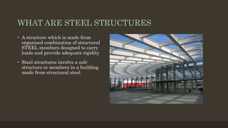
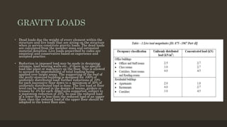
Multi-storey Frames
Lalith Kumar Rishav Raj
Anmol Chugh Abhigya Sharan
WHAT ARE STEEL STRUCTURES
• A structure which is made from
organised combination of structural
STEEL members designed to carry
loads and provide adequate rigidity
• Steel structures involve a sub-
structure or members in a building
made from structural steel.
WHERE STEEL FRAME STRUCTURES ARE
USED
Steel construction is most often used in -
• High rise buildings because of its strength, low weight, and speed of construction
• Industrial buildings because of its ability to create large span spaces at low cost
• Warehouse buildings for the same reason
• Residential buildings in a technique called light gauge steel construction
• Temporary Structures as these are quick to set up and remove
ADVANTAGES OF STEEL STRUCTURES
• Steel structures have the following advantages:
They are super-quick to build at site, as a lot of work can be pre-fabbed at the factory.
• They are flexible, which makes them very good at resisting dynamic (changing) forces
such as wind or earthquake forces.
• A wide range of ready-made structural sections are available, such as I, C, and angle
sections
• They can be made to take any kind of shape, and clad with any type of material
• A wide range of joining methods is available, such as bolting, welding, and riveting
DISADVANTAGES OF STEEL STRUCTURES
Steel structures have the following disadvantages:
• They lose strength at high temperatures, and are susceptible to fire.
• They are prone to corrosion in humid or marine environments.
• Heavy and lengthy, not easy to handle
• Deflect under loads
DIFFERENT TYPES OF STRUCTURAL FRAMES
BEAM AND COLUMN CONSTRUCTION FRAME
• This is often called as “skeleton
construction”. The floor slabs, partitions,
exterior walls etc. are all supported by a
framework of steel beams and columns.
This type of skeleton structure can be
erected easily leading to very tall
buildings.
• Generally columns used in the
framework are hot-rolled I-sections or
concrete encased steel columns. They
give unobstructed access for beam
connections through either the flange or
the web. Where the loading
requirements exceed the capacity of
available section, additional plates are
welded to the section
LONG SPAN BEAMS
• The layout of floor beams in buildings depends
largely on the spacing of the columns. The
columns along the perimeter of the building are
generally spaced at 5 to 8 m in order to support
the façade elements. In most buildings, the
secondary beams are designed to span the longer
distance in the floor grid, so that the bending
moment they resist is similar to that of the
primary beams and therefore they can be of the
same depth as the primary beams.
• In many buildings, designing longer internal
spans creates more flexible space planning. A
variety of structural steel systems may be used
to provide either long-span primary beams or
secondary beams. These long-span
systems generally use the principles
of composite construction to increase their
stiffness and strength, and often provide
for integration of services within their depth via
openings in the webs of the beams.
TRUSSES
• Trusses and lattice girders are used in long
span roofing and flooring systems. The term
‘truss’ is generally applied to roofs, which may
be pitched, whereas lattice girders are
generally used as long-span floor
beams which are more heavily loaded and not
pitched.
• Trusses and lattice girders are often designed
to be visible and therefore the choice of the
members used and their connections is
important to the design solution.
• Trusses and lattice girders are triangular or
rectangular assemblies of tension and
compression elements. The top and bottom
chords provide the compression and tension
resistance to overall bending, and the inclined
bracing elements resist the shear forces.
SPACE FRAMES
• A ‘space’ frame is a form of construction that covers large areas
using assemblies of small structural components that are
connected at pre-formed nodes. They are three-dimensional
assemblies that generally consist of tension and compression
elements, connected by inclined bracing. Circular hollow
sections (CHS) are generally used in space frames as their wall
thickness can be varied to suit the forces in the members while
maintaining a constant outside diameter. There are three
generic forms of support to space frames that determine the
forces to which they are subject:
• Point support by columns at four or more positions
• Multiple supports by rows of columns or ‘column trees’.
• Continuous edge support.
• An example of the multiple point supports to a double layer
space frame over a pedestrian street in Belfast’s Victoria
Centre
SHEAR WALL FRAMES
• The lateral loads are assumed to be concentrated
at the floor levels. The rigid floors spread these
forces to the columns or walls in the building.
Lateral forces are particularly large in case of
tall buildings or when seismic forces are
considered. Specially designed, reinforced
concrete walls parallel to the directions of load
are used to resist a large part of the lateral loads
caused by wind or earthquakes by acting as deep
cantilever beams fixed at foundation. These
elements are called as shear walls.
• . The advantages of shear walls are (i) they are
very rigid in their own plane and hence are
effective in limiting deflections and (ii) they act
as fire compartment walls
• Generally reinforced concrete walls possess
sufficient strength and stiffness to resist the
lateral loading. Shear walls have lesser ductility
and may not meet the energy required under
severe earthquake. A typical framed structure
braced with core wall is shown
FRAMED TUBE STRUCTURES
• The framed tube is one of the most
significant modern developments in
high-rise structural form. The frames
consist of closely spaced columns, 2 - 4
m between centres, joined by deep
girders. The idea is to create a tube
that will act like a continuous,
perforated chimney or stack.
• The lateral resistance of framed tube
structures is provided by very stiff
moment resisting frames that form a
tube around the perimeter of the
building.
TUBE IN TUBE FRAME
• This is a type of framed tube consisting
of an outer-framed tube together with
an internal elevator and service core.
• The inner tube may consist of braced
frames. The outer and inner tubes act
jointly in resisting both gravity and
lateral loading in steel-framed
buildings. However, the outer tube
usually plays a dominant role because
of its much greater structural depth.
This type of structures is also called as
Hull (Outer tube) and Core (Inner
tube) structures.
BRACED FRAMES
• The majority of structural systems used in office construction
are braced by one of two methods;
• Steel bracing, generally in the form of cross-flat plates or hollow
sections that are located in the façade walls, or in internal separating
walls, or around service areas and stairs.
• Concrete or steel plated cores that enclose the stairs and lifts, service
risers, toilets etc.
• The choice of this system depends on the form and scale of the
buildings. In most buildings up to 6 storeys high, steel bracing is
preferred, although its location is strongly influenced by the layout of
the building. V or K bracing using tubular sections is often preferred as
it is more compact and can be arranged around windows and doors in
some cases. X flat bracing is preferred for use in brickwork as it can be
located in the cavity between the leaves of the brickwork.
• For taller buildings, concrete cores are more efficient and they can
either be constructed floor by floor using conventional formwork, or slip-
formed continuously. The relative economics is dictated by speed of
construction, and slip forming is often used on tall buildings. Steel
plated or composite cores are also used where there is need to minimise
the space occupied by the core and where it can be constructed in
parallel with the steel framework.
• The structural design of the steel frame is therefore based on the use of
simple shear resisting connections for both the beam to column and
beam to beam connections.
CONTINOUS FRAMES
• Continuous frames achieve continuity of
the beams either by design of the steel structure so
that they are multi-span, or by use of moment-
resisting connections.
• In the Palestra building, the primary beams were
arranged in pairs either side of the tubular
columns, and the beams were continuous across the
building, being spliced only at the quarter span
positions from the internal columns where bending
moment were low. In that way, the beams are stiffer
due to their continuity than the equivalent simply
supported beam and so that depth can be reduced. A
view of the building during construction is shown.
• In buildings up to four storeys in height, it may be
economic to design the steel structure as a sway
frame to resist lateral loads applied to the building.
The connections between the beams and
the columns are made moment-resisting by use of
extended end plate connections. The columns may
be heavier than in simply supported design, but
the beams can be lighter, and bracing is eliminated.
This may be advantageous in low-rise buildings
with highly glazed facades.
LOADS TO BE CONSIDERED
GRAVITY LOADS
• Dead loads due the weight of every element within the
structure and live loads that are acting on the structure
when in service constitute gravity loads. The dead loads
are calculated from the member sizes and estimated
material densities. Live loads prescribed by codes are
empirical and conservative based on experience and
accepted practice.
• Reduction in imposed load may be made in designing
columns, load bearing walls etc., if there is no specific
load like plant or machinery on the floor. This is allowed
to account for improbability of total loading being
applied over larger areas. The supporting of the roof of
the multi-storeyed building is designed for 100% of
uniformly distributed load; further reductions of 10%
for each successive floor down to a minimum of 50% of
uniformly distributed load is done. The live load at floor
level can be reduced in the design of beams, girders or
trusses by 5% for each 50m2 area supported, subject to
a maximum reduction of 25%. In case the reduced load
of a lower floor is less than the reduced load of an upper
floor, then the reduced load of the upper floor should be
adopted in the lower floor also.
WIND LOADS
• The wind loading is the most
important factor that determines the
design of tall buildings over 10 storeys,
where storey height approximately lies
between 2.7 – 3.0 m. Buildings of up to
10 storeys, designed for gravity loading
can accommodate wind loading
without any additional steel for lateral
system. Usually, buildings taller than
10 storeys would generally require
additional steel for lateral system. This
is due to the fact that wind loading on
a tall building acts over a very large
building surface, with greater intensity
at the greater heights and with a
larger moment arm about the base.
SEISMIC LOADS
• Seismic motion consists of horizontal
and vertical ground motions, with the
vertical motion usually having a much
smaller magnitude. Further, factor of
safety provided against gravity loads
usually can accommodate additional
forces due to vertical acceleration due
to earthquakes. So, the horizontal
motion of the ground causes the most
significant effect on the structure by
shaking the foundation back and forth.
The mass of building resists this
motion by setting up inertia forces
throughout the structure.
INFERENCE
Loading on tall buildings is different from low-rise buildings in many ways such as large
accumulation of gravity loads on the floors from top to bottom, increased significance of wind loading
and greater importance of dynamic effects. Thus, multi-storeyed structures need correct assessment
of loads for safe and economical design. Excepting dead loads, the assessment of loads can not be
done accurately. Live loads can be anticipated approximately from a combination of experience and
the previous field observations. But, wind and earthquake loads are random in nature. It is difficult
to predict them exactly. These are estimated based on probabilistic approach.

Multi storey frames

  • 1.
    Multi-storey Frames Lalith KumarRishav Raj Anmol Chugh Abhigya Sharan
  • 2.
    WHAT ARE STEELSTRUCTURES • A structure which is made from organised combination of structural STEEL members designed to carry loads and provide adequate rigidity • Steel structures involve a sub- structure or members in a building made from structural steel.
  • 3.
    WHERE STEEL FRAMESTRUCTURES ARE USED Steel construction is most often used in - • High rise buildings because of its strength, low weight, and speed of construction • Industrial buildings because of its ability to create large span spaces at low cost • Warehouse buildings for the same reason • Residential buildings in a technique called light gauge steel construction • Temporary Structures as these are quick to set up and remove
  • 4.
    ADVANTAGES OF STEELSTRUCTURES • Steel structures have the following advantages: They are super-quick to build at site, as a lot of work can be pre-fabbed at the factory. • They are flexible, which makes them very good at resisting dynamic (changing) forces such as wind or earthquake forces. • A wide range of ready-made structural sections are available, such as I, C, and angle sections • They can be made to take any kind of shape, and clad with any type of material • A wide range of joining methods is available, such as bolting, welding, and riveting
  • 5.
    DISADVANTAGES OF STEELSTRUCTURES Steel structures have the following disadvantages: • They lose strength at high temperatures, and are susceptible to fire. • They are prone to corrosion in humid or marine environments. • Heavy and lengthy, not easy to handle • Deflect under loads
  • 6.
    DIFFERENT TYPES OFSTRUCTURAL FRAMES
  • 7.
    BEAM AND COLUMNCONSTRUCTION FRAME • This is often called as “skeleton construction”. The floor slabs, partitions, exterior walls etc. are all supported by a framework of steel beams and columns. This type of skeleton structure can be erected easily leading to very tall buildings. • Generally columns used in the framework are hot-rolled I-sections or concrete encased steel columns. They give unobstructed access for beam connections through either the flange or the web. Where the loading requirements exceed the capacity of available section, additional plates are welded to the section
  • 8.
    LONG SPAN BEAMS •The layout of floor beams in buildings depends largely on the spacing of the columns. The columns along the perimeter of the building are generally spaced at 5 to 8 m in order to support the façade elements. In most buildings, the secondary beams are designed to span the longer distance in the floor grid, so that the bending moment they resist is similar to that of the primary beams and therefore they can be of the same depth as the primary beams. • In many buildings, designing longer internal spans creates more flexible space planning. A variety of structural steel systems may be used to provide either long-span primary beams or secondary beams. These long-span systems generally use the principles of composite construction to increase their stiffness and strength, and often provide for integration of services within their depth via openings in the webs of the beams.
  • 9.
    TRUSSES • Trusses andlattice girders are used in long span roofing and flooring systems. The term ‘truss’ is generally applied to roofs, which may be pitched, whereas lattice girders are generally used as long-span floor beams which are more heavily loaded and not pitched. • Trusses and lattice girders are often designed to be visible and therefore the choice of the members used and their connections is important to the design solution. • Trusses and lattice girders are triangular or rectangular assemblies of tension and compression elements. The top and bottom chords provide the compression and tension resistance to overall bending, and the inclined bracing elements resist the shear forces.
  • 10.
    SPACE FRAMES • A‘space’ frame is a form of construction that covers large areas using assemblies of small structural components that are connected at pre-formed nodes. They are three-dimensional assemblies that generally consist of tension and compression elements, connected by inclined bracing. Circular hollow sections (CHS) are generally used in space frames as their wall thickness can be varied to suit the forces in the members while maintaining a constant outside diameter. There are three generic forms of support to space frames that determine the forces to which they are subject: • Point support by columns at four or more positions • Multiple supports by rows of columns or ‘column trees’. • Continuous edge support. • An example of the multiple point supports to a double layer space frame over a pedestrian street in Belfast’s Victoria Centre
  • 11.
    SHEAR WALL FRAMES •The lateral loads are assumed to be concentrated at the floor levels. The rigid floors spread these forces to the columns or walls in the building. Lateral forces are particularly large in case of tall buildings or when seismic forces are considered. Specially designed, reinforced concrete walls parallel to the directions of load are used to resist a large part of the lateral loads caused by wind or earthquakes by acting as deep cantilever beams fixed at foundation. These elements are called as shear walls. • . The advantages of shear walls are (i) they are very rigid in their own plane and hence are effective in limiting deflections and (ii) they act as fire compartment walls • Generally reinforced concrete walls possess sufficient strength and stiffness to resist the lateral loading. Shear walls have lesser ductility and may not meet the energy required under severe earthquake. A typical framed structure braced with core wall is shown
  • 12.
    FRAMED TUBE STRUCTURES •The framed tube is one of the most significant modern developments in high-rise structural form. The frames consist of closely spaced columns, 2 - 4 m between centres, joined by deep girders. The idea is to create a tube that will act like a continuous, perforated chimney or stack. • The lateral resistance of framed tube structures is provided by very stiff moment resisting frames that form a tube around the perimeter of the building.
  • 13.
    TUBE IN TUBEFRAME • This is a type of framed tube consisting of an outer-framed tube together with an internal elevator and service core. • The inner tube may consist of braced frames. The outer and inner tubes act jointly in resisting both gravity and lateral loading in steel-framed buildings. However, the outer tube usually plays a dominant role because of its much greater structural depth. This type of structures is also called as Hull (Outer tube) and Core (Inner tube) structures.
  • 14.
    BRACED FRAMES • Themajority of structural systems used in office construction are braced by one of two methods; • Steel bracing, generally in the form of cross-flat plates or hollow sections that are located in the façade walls, or in internal separating walls, or around service areas and stairs. • Concrete or steel plated cores that enclose the stairs and lifts, service risers, toilets etc. • The choice of this system depends on the form and scale of the buildings. In most buildings up to 6 storeys high, steel bracing is preferred, although its location is strongly influenced by the layout of the building. V or K bracing using tubular sections is often preferred as it is more compact and can be arranged around windows and doors in some cases. X flat bracing is preferred for use in brickwork as it can be located in the cavity between the leaves of the brickwork. • For taller buildings, concrete cores are more efficient and they can either be constructed floor by floor using conventional formwork, or slip- formed continuously. The relative economics is dictated by speed of construction, and slip forming is often used on tall buildings. Steel plated or composite cores are also used where there is need to minimise the space occupied by the core and where it can be constructed in parallel with the steel framework. • The structural design of the steel frame is therefore based on the use of simple shear resisting connections for both the beam to column and beam to beam connections.
  • 15.
    CONTINOUS FRAMES • Continuousframes achieve continuity of the beams either by design of the steel structure so that they are multi-span, or by use of moment- resisting connections. • In the Palestra building, the primary beams were arranged in pairs either side of the tubular columns, and the beams were continuous across the building, being spliced only at the quarter span positions from the internal columns where bending moment were low. In that way, the beams are stiffer due to their continuity than the equivalent simply supported beam and so that depth can be reduced. A view of the building during construction is shown. • In buildings up to four storeys in height, it may be economic to design the steel structure as a sway frame to resist lateral loads applied to the building. The connections between the beams and the columns are made moment-resisting by use of extended end plate connections. The columns may be heavier than in simply supported design, but the beams can be lighter, and bracing is eliminated. This may be advantageous in low-rise buildings with highly glazed facades.
  • 16.
    LOADS TO BECONSIDERED
  • 17.
    GRAVITY LOADS • Deadloads due the weight of every element within the structure and live loads that are acting on the structure when in service constitute gravity loads. The dead loads are calculated from the member sizes and estimated material densities. Live loads prescribed by codes are empirical and conservative based on experience and accepted practice. • Reduction in imposed load may be made in designing columns, load bearing walls etc., if there is no specific load like plant or machinery on the floor. This is allowed to account for improbability of total loading being applied over larger areas. The supporting of the roof of the multi-storeyed building is designed for 100% of uniformly distributed load; further reductions of 10% for each successive floor down to a minimum of 50% of uniformly distributed load is done. The live load at floor level can be reduced in the design of beams, girders or trusses by 5% for each 50m2 area supported, subject to a maximum reduction of 25%. In case the reduced load of a lower floor is less than the reduced load of an upper floor, then the reduced load of the upper floor should be adopted in the lower floor also.
  • 18.
    WIND LOADS • Thewind loading is the most important factor that determines the design of tall buildings over 10 storeys, where storey height approximately lies between 2.7 – 3.0 m. Buildings of up to 10 storeys, designed for gravity loading can accommodate wind loading without any additional steel for lateral system. Usually, buildings taller than 10 storeys would generally require additional steel for lateral system. This is due to the fact that wind loading on a tall building acts over a very large building surface, with greater intensity at the greater heights and with a larger moment arm about the base.
  • 19.
    SEISMIC LOADS • Seismicmotion consists of horizontal and vertical ground motions, with the vertical motion usually having a much smaller magnitude. Further, factor of safety provided against gravity loads usually can accommodate additional forces due to vertical acceleration due to earthquakes. So, the horizontal motion of the ground causes the most significant effect on the structure by shaking the foundation back and forth. The mass of building resists this motion by setting up inertia forces throughout the structure.
  • 20.
    INFERENCE Loading on tallbuildings is different from low-rise buildings in many ways such as large accumulation of gravity loads on the floors from top to bottom, increased significance of wind loading and greater importance of dynamic effects. Thus, multi-storeyed structures need correct assessment of loads for safe and economical design. Excepting dead loads, the assessment of loads can not be done accurately. Live loads can be anticipated approximately from a combination of experience and the previous field observations. But, wind and earthquake loads are random in nature. It is difficult to predict them exactly. These are estimated based on probabilistic approach.