Downloaded 304 times
![TELECOMMUNICATION
SERVICES FOR
HIGH RISE BUILDINGS
Taylor’s University
School of Architecture, Building and Design
Bachelor of Quantity Surveying (Hons)
Building Services I [BLD60403]
Assignment 1 - Presentation](https://image.slidesharecdn.com/completeslides-151126002912-lva1-app6891/85/Telecommunication-Services-for-High-Rise-Buildings-1-320.jpg)
![TELECOMMUNICATION
SERVICES FOR
HIGH RISE BUILDINGS
Taylor’s University
School of Architecture, Building and Design
Bachelor of Quantity Surveying (Hons)
Building Services I [BLD60403]
Assignment 1 - Presentation](https://image.slidesharecdn.com/completeslides-151126002912-lva1-app6891/75/Telecommunication-Services-for-High-Rise-Buildings-1-2048.jpg)

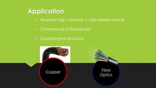
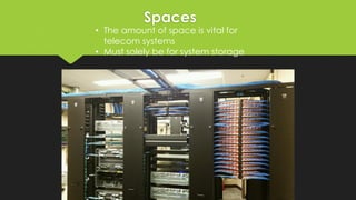

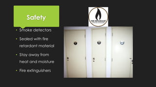
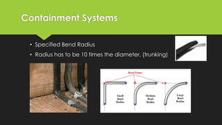
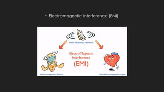

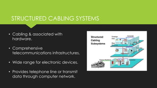


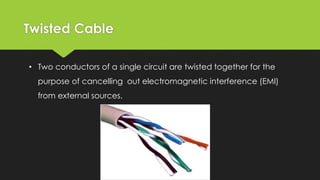


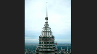
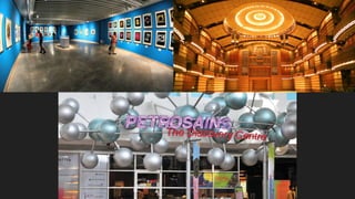
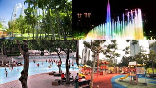
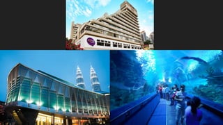
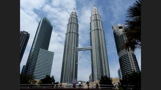
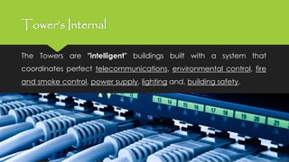

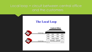
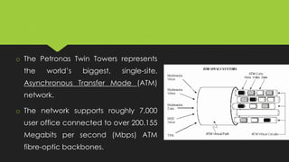


The document discusses telecommunication services for high-rise buildings. It introduces telecommunication systems and challenges in high-rise buildings like fire safety and efficient service. It covers applications like fiber optics and copper cables. It also discusses structured cabling systems, main distribution frames, telecom rooms, and network architectures. Finally, it examines potential problems like damage to cables, maintenance issues, and space shortages as well as examples of cable types. A case study on the Petronas Twin Towers elaborates on its sophisticated internal telecom infrastructure designed to support worldwide operations.


![Principle of Economics [ECN 30205] - A Tale of Two Businesses](https://cdn.slidesharecdn.com/ss_thumbnails/full2-150124195533-conversion-gate01-thumbnail.jpg?width=640&height=640&fit=bounds)


