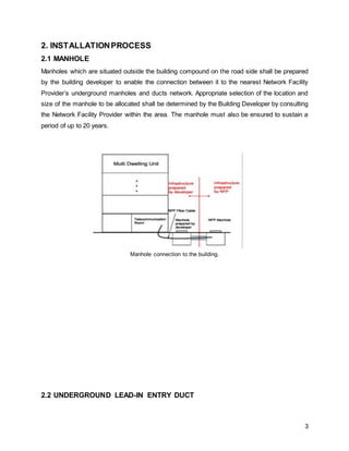
This document provides details on the installation process and management system for telecommunication services in a high-rise building. It discusses the various components involved from the manhole and underground entry duct, to the main telecommunication room, fibre termination boxes, riser rooms, mobile service rooms, consolidation cabinets, and fibre wall sockets. Containment systems including vertical and horizontal cabling are also outlined. Lastly, it emphasizes the importance of an effective management system to support the large number of users and ensure consistent, reliable access.
Building services engineering, technical building services, architectural engineering, building engineering, or facilities and services planning engineering refers to the implementation of the engineering for the internal environment and environmental impact of a building.
Project 1: Industrialised Building System [ IBS ]JerotichMaswan
Project 1 of Advanced Architectural Construction.
Requirement: Design a 3 storey apartment building using Precast Concrete System. Other IBS systems are allowed. Create a report on IBS and the building detailing.
Passive Fire Protection According to UBBL MalaysiaZhao Wei Kim
Design and Application of passive fire protection stated in Uniform Building By-Laws of Malaysia. It contains graphical guidance to make the law items easier to comprehend and apply.
Credit to: UTM alumni
building control - process of building plan approval
by :
wan nur izzati binti wan mohd yusli
siti nur zarina binti mohamad
wan nurul nabihah binti wan zulkefly
nurul nadhirah binti zulkefli
Roxtec cable transit systems provide cable entry seals for telecom networks, mobile and fixed-line installations - Roxtec cable entry seals have been designed for maximum customer benefit both in terms of reliable protection and ease of use.
Roxtec Cable Transit & Cable Entry Seales - Telecomms Applications
*Outdoor cabinets - sealing cables passing from outside to inside of a cabinet
*Roof top site - cable seal through the outer wall of building for antenna cables
*Radiolink - roof-top cable seal handling antenna cables on roof construction
*3G Base Station Shelter - sealing of feeders through the wall
*Base station shelter - round cable sealing solution for openings in port hole
*Communication centres - sealing fibre optics and cables in floors and walls
*Switch station - cable seals through floors and walls in the switch station
*Buildings - sealing of feeding cables into buildings
*Railway - sealing of cables for GSM-R through wall and floor of shelters
*FTTH - conduits of fibre optics sealed in the foundation of network shelters
*Cabinets - cable entry solution to seal cables in outdoor cabinets
*Manhole - sealing of power cables in underground vaults
Project ManagementOf Telecom Project A Case StudyDjadja Sardjana
For ease of comprehension, study on the development of passive infrastructure has been designed to first present the theoretical concepts and then correlating them to actual applications in the field by applying them into examples. Topics include scope of work, project planning, contractual terms of conditions, monitoring and controlling of project quality control, risk management, warehouse management, operation and maintenance.
The French Revolution, which began in 1789, was a period of radical social and political upheaval in France. It marked the decline of absolute monarchies, the rise of secular and democratic republics, and the eventual rise of Napoleon Bonaparte. This revolutionary period is crucial in understanding the transition from feudalism to modernity in Europe.
For more information, visit-www.vavaclasses.com
Operation “Blue Star” is the only event in the history of Independent India where the state went into war with its own people. Even after about 40 years it is not clear if it was culmination of states anger over people of the region, a political game of power or start of dictatorial chapter in the democratic setup.
The people of Punjab felt alienated from main stream due to denial of their just demands during a long democratic struggle since independence. As it happen all over the word, it led to militant struggle with great loss of lives of military, police and civilian personnel. Killing of Indira Gandhi and massacre of innocent Sikhs in Delhi and other India cities was also associated with this movement.
Synthetic Fiber Construction in lab .pptxPavel ( NSTU)
Synthetic fiber production is a fascinating and complex field that blends chemistry, engineering, and environmental science. By understanding these aspects, students can gain a comprehensive view of synthetic fiber production, its impact on society and the environment, and the potential for future innovations. Synthetic fibers play a crucial role in modern society, impacting various aspects of daily life, industry, and the environment. ynthetic fibers are integral to modern life, offering a range of benefits from cost-effectiveness and versatility to innovative applications and performance characteristics. While they pose environmental challenges, ongoing research and development aim to create more sustainable and eco-friendly alternatives. Understanding the importance of synthetic fibers helps in appreciating their role in the economy, industry, and daily life, while also emphasizing the need for sustainable practices and innovation.
Welcome to TechSoup New Member Orientation and Q&A (May 2024).pdfTechSoup
In this webinar you will learn how your organization can access TechSoup's wide variety of product discount and donation programs. From hardware to software, we'll give you a tour of the tools available to help your nonprofit with productivity, collaboration, financial management, donor tracking, security, and more.
A Strategic Approach: GenAI in EducationPeter Windle
Artificial Intelligence (AI) technologies such as Generative AI, Image Generators and Large Language Models have had a dramatic impact on teaching, learning and assessment over the past 18 months. The most immediate threat AI posed was to Academic Integrity with Higher Education Institutes (HEIs) focusing their efforts on combating the use of GenAI in assessment. Guidelines were developed for staff and students, policies put in place too. Innovative educators have forged paths in the use of Generative AI for teaching, learning and assessments leading to pockets of transformation springing up across HEIs, often with little or no top-down guidance, support or direction.
This Gasta posits a strategic approach to integrating AI into HEIs to prepare staff, students and the curriculum for an evolving world and workplace. We will highlight the advantages of working with these technologies beyond the realm of teaching, learning and assessment by considering prompt engineering skills, industry impact, curriculum changes, and the need for staff upskilling. In contrast, not engaging strategically with Generative AI poses risks, including falling behind peers, missed opportunities and failing to ensure our graduates remain employable. The rapid evolution of AI technologies necessitates a proactive and strategic approach if we are to remain relevant.
2024.06.01 Introducing a competency framework for languag learning materials ...Sandy Millin
http://sandymillin.wordpress.com/iateflwebinar2024
Published classroom materials form the basis of syllabuses, drive teacher professional development, and have a potentially huge influence on learners, teachers and education systems. All teachers also create their own materials, whether a few sentences on a blackboard, a highly-structured fully-realised online course, or anything in between. Despite this, the knowledge and skills needed to create effective language learning materials are rarely part of teacher training, and are mostly learnt by trial and error.
Knowledge and skills frameworks, generally called competency frameworks, for ELT teachers, trainers and managers have existed for a few years now. However, until I created one for my MA dissertation, there wasn’t one drawing together what we need to know and do to be able to effectively produce language learning materials.
This webinar will introduce you to my framework, highlighting the key competencies I identified from my research. It will also show how anybody involved in language teaching (any language, not just English!), teacher training, managing schools or developing language learning materials can benefit from using the framework.
Introduction to AI for Nonprofits with Tapp NetworkTechSoup
Dive into the world of AI! Experts Jon Hill and Tareq Monaur will guide you through AI's role in enhancing nonprofit websites and basic marketing strategies, making it easy to understand and apply.
Introduction to AI for Nonprofits with Tapp Network
Building services Report
1. BLD 60403 BUILDING SERVICES I
TELECOMMUNICATION SERVICE
FOR HIGH RISE BUILDING
NO STUDENT ID NAME
1 0320087 LILLIAN TAN AI JUN
2 0321683 LING SUE ER
3 0320221 NGIENG TIEN YUNG
4 0320275 TERENCE TAN PENG ONG
5 0320199 TAN MING HOWE
6 0319962 OOI YIN JI
7 0320142 CHIA LY VIER
LECTURER : MS LIM TZE SHWAN
SUBMISSION DATE : 28TH JUNE 2016
CONTENT
2. 1
No. Content Page Number
1. Introduction 2
2. Installation process 3-17
3. Management system 18-20
4. Advantages and disadvantages 21-23
5. Case study 24-30
6. Possible problems of telecommunication system 31-33
7. Recommendations 34-36
8. Reflection 37
9. References 38-40
3. 2
1. INTRODUCTION
This report is a summarised research of the assigned topic “Telecommunication Services for
High-Rise Building”. Different aspects of the selected topic such as the installation process,
management system, advantages and disadvantages of different cabling system, possible
problems encountered, solution and recommendations for future improvement have been
covered and further discussed in the report. Case studies have also been carried out to enable
a comparison of two selected telecom buildings in different location, namely Al Hamra in Kuwait
City and Telekom Tower in Malaysia.
According to Oxford Dictionary, telecommunication means communication over a long distance
by using different channels such as telephone, radio, fax, wireless network and etc. Generally, a
complete telecommunication circuit consists of two telecom stations, a transmitter and a
receiver. A transmitter is a sender that converts messages from the source and transmit them in
a form of signal while the receiver functions to pass the signal to its destination through a
transmission medium by converting it back to usable information.
Besides, communication signals are usually grouped into two different categories, analog
signals and digital signals. An analog signal is a continuous waveform used in voice
communication while a digital signal is a discrete waveform which usually requires technical
processing as it is interpreted in a form of binary codes used for data communication.
Last but not least, the application of telecom system may vary according to the types of
premises such that a multiple-dwelling unit (MDU) might require a more complex installation,
higher cost, regular maintenance, larger storage space for the accommodation of system in
comparison to a single-dwelling unit (SDU). In this report, special focus will be given to the
MDU, the high-rise building and the information obtained is discussed and summarised in the
followings.
4. 3
2. INSTALLATIONPROCESS
2.1 MANHOLE
Manholes which are situated outside the building compound on the road side shall be prepared
by the building developer to enable the connection between it to the nearest Network Facility
Provider’s underground manholes and ducts network. Appropriate selection of the location and
size of the manhole to be allocated shall be determined by the Building Developer by consulting
the Network Facility Provider within the area. The manhole must also be ensured to sustain a
period of up to 20 years.
Manhole connection to the building.
2.2 UNDERGROUND LEAD-IN ENTRY DUCT
5. 4
The underground duct-ways serve to route the connection between the manhole to the
Telecommunication Room (TR) inside the building. The duct routes must not be obstructed and
shall be straightly aligned without any sharp bends such that the maximum allowable bending
radius is 20 times of the duct diameter.
Bending radius of the underground entry duct shall not exceed 20 times of the duct diameter.
Besides, the building developer shall also ensure that the ducting system constructed has a
minimal risk of exposure to environmental hazards such as soil erosion, landscape
deterioration, flood, earthquake and storms. In the area where such condition is not avoidable,
proper planning and maintenance shall be carried out from time to time to ensure that the
ducting system is well-maintained at good condition.
Underground entry duct routed to Telecommunication Room inside the building at ground floor level
The specifications of the underground lead-in entry duct are as follows:
● Made from black uPVC
6. 5
● The uppermost part of the duct must be buried to a depth of 600mm below the finished
ground level
● The ducts shall be clearly marked above the ground level for easy location
● Protected by concrete encasement when running under permanently-paved surfaces.
● Each end must be sealed to prevent the ingress of unwanted materials such as water,
sub-soil, gas, and pests.
● Installation of an entry or pull box is necessary for any right-angled or sharp bends in the
lead-in duct route.
2.3 MAIN TELECOMMUNICATION ROOM (MTR)
A main telecommunication room must be provided on the ground floor of the building which is of
6 storeys high and above. This room houses the telecom equipments and serves not only as a
main termination point for all the telecom fibre cables but also as a demarcation point used for
intermediate and main cross-connects (distributor). Generally, the MTR can be shared by both
telecom fixed and mobile services. Fixed telecom services are such as fiber optic network for
the Internet, landline telephone and fixed-line broadband while mobile telecom services may
7. 6
include mobile telephone calls, mobile data usage, short message service (sms), mobile data
access and more. If a mobile service room is required in the building, the first mobile service
landing room can be shared with the MTR. The minimum dimension for the combined room
should be 4m x 4m x 3m (WxDxH) and may be increased according to the functions and
features of the building. If the rooms-sharing is not applicable due to the limit of the building
architectural design, then the two dedicated rooms shall each be constructed at a minimum size
of 3m x 3m x 3m (WXDXH).
Room specification of Main Telecommunication Room (MTR) with Fixed and Mobile Services
8. 7
Wall mount Optical Distribution Frame (ODF) inside Main Telecommunication Room (MTR)
A 3m height clearance shall be provided as the minimum finished clearance after taking into
account for allowances made for raised floors (if used), overhead cable trays and any other
obstructions such as lighting fixtures and beams. In the case where overhead trays are used, a
minimum headroom access of 300mm is to be provided above the tray. MTR which consists of
active telecom equipment, particularly in a commercial or mixed-use building, might require a
‘raised floor’ depending on the telecom room usage. A minimum of 300mm height above the
base floor of the room should be provided. However, a raised floor may not be mandatory when
it comes to residential buildings.
Besides, the floor level of the room shall be at the same level as the corridor or outer access. If
the case where this condition cannot be met, a ramped entry with an anti-slip surface shall be
provided. A 100mm threshold step must also be provided inside the room under the raised floor
to prevent any ingress of water from outside the room. The door of the main telecom room
should be labelled “Main Telecom Room” and have an outward opening with size not smaller
than 900mm x 2100mm (WxH). All cables in the main telecom room must be properly routed to
the desired destinations.
2.4 MOBILE SERVICE ROOM
As mentioned earlier, the telecom fixed and mobile services are allowed to be stored and
combined in a single room. The first mobile service room can be shared with the MTR to serve
the first 10 floors of the building. If sharing is not feasible, the mobile service room can be
provided in a separate space sized with 3m x3m x3m (WxDxH). Besides, the room shall also be
provided subsequently for every 10 floors thereafter. The room should be located near to the
floor telecom closet (FTC) which is the ‘riser room’. The minimum distributed floor load rating of
9. 8
the room is 10 kN/m2 while the dimension of the door is standardized at 900mm x 2100mm
(WxH) with an outward opening. The doors should be labelled ‘Mobile Room Service’
Combined MTR and mobile service room
Separate MTR and mobile service
room
2.5 MAIN DISTRIBUTION FRAME (MDF)
A Main Distribution Frame (MDF) is a signal distribution frame or cable rack used in telephony
to manage and interlink telecommunication wiring between itself and any number of
intermediate distribution frames (IDF) and cabling from the telephony network it supports. The
MDF operates to allow the connection between equipments inside a telecommunications facility
to cables and subscriber carrier equipment. Every cable that supplies services to user
10. 9
telephones lines would end up at the MDF to be distributed to equipment within the local
exchanges.
The most common kind of MDF is a long steel rack having both sides accessible. A typical MDF
can carry hundreds or thousands of jumpers that are able to sustain for a long period of time
and can be maintained without entanglement when administered by experienced professionals.
Jumpers are twisted pairs of cable, whereby each one is corresponded to an individual
telephone line.
Free-standing MDF that can be moved individually to allow installation of cables
2.6 FIBRE TERMINATION BOX (FTB)
11. 10
Interior look of FTB (left) and its routes in a building (right)
In a multiple-dwelling unit (MDU), the Fibre Termination Box (FTB) serves as a fibre termination
point at the telecommunication room (TR) and the riser room or floor telecom closet (FTC). The
FTB helps to connect the Network Facility Provider’s fibres to the in-building fibre cables. It also
operates as a distribution point for in-building cabling. The material used for the termination box
shall be able to protect the components within against harsh, high heat and humidity
environment. The framework of the premise fibre termination box shall be made of fire retardant
material. Each fibre termination box shall be provided with a table or label card for circuit
identification purpose.
2.7 RISER ROOM / FLOOR TELECOM CLOSET (FTC)
12. 11
Layout of Floor Telecom Closet (FTC)
A floor telecom closet which generally known as the ‘riser room’ must be provided on each floor
of the MDU. The floor telecom closet serves to provide a flexible point for the installation, pulling
and maintenance of telecom cables. The minimum dimension of FTC is 2m x 1m x 3m
(WXDXH) with two outward opening doors that has a minimum total size of 1500mm x 2100mm
(WxH). The door should be labelled ‘Floor Telecom Closet’.
In case of commercial shell and core development (open space office floor with no predefined
usage), installation of an indoor wall mount mini ODF (Optical Distribution Frame) inside the
floor telecom closet (FTC) shall be carried out by the building contractor. The size of the mini
ODF varies with the number of fibre cores required based on the floor area served. Moreover,
free wall space inside the floor telecom closet must be reserved for future fibre terminations.
Mini ODF specifications are as follows:
• Lockable side panels and front door.
• Sufficient cable entries to accommodate the incoming fibre optic cables.
• Labelled with floor number.
2.8 MOBILE SERVICE ANTENNA
13. 12
The mobile service antenna cables are routed via cable trays from the floor telecom closets
(FTC) to all common corridors including lift lobbies at every floor, podium and basement. For
office or commercial buildings, the horizontal containments should be extended till it reaches the
entrance of each office units. The minimum dimension of the cable tray should be of 200mm x
50mm (WxH) with Heavy Duty Return Flange (HDRF) as a main route from floor telecom closet
to main corridors and then branches to each consolidation cabinet through smaller cable trays
with size of 50mm x 50mm (WxH).
Mobile service
antenna routes from the floor telecom closet (FTC) to main corridor of each floor
2.9 CONSOLIDATION CABINET
14. 13
Layout of a typical consolidation cabinet
The consolidation cabinet is used to house the network termination equipment. It also serves as
the distribution point for all local wiring. A consolidation cabinet should be provided in each unit
of the premises.The minimum specifications of a telecom cabinet are as follows :
● Located in an accessible area close to the entrance, avoiding areas such as kitchen,
laundry room or bedroom.
● Adequate ventilation with ambient temperature maintained at 20°C - 30°C.
● Adequate safe working space around the location with proper lighting.
● Not close to any water or heat sources and any electrical distribution.
● Clearly labelled with office/retail/building unit number.
2.10 FIBRE WALL SOCKET (FWS)
15. 14
Fibre wall socket (FWS) is provided in each unit of the MDU. (right)
Intermediate junction box for individual cable run with sharp change in direction. (left)
The Fibre Wall Socket (FWS) serves as a termination point for the internal fibre cable and a
connection point to the Customer Premise Equipment (CPE). All the unshielded twisted pair
16. 15
(UTP) cables within the unit must run through PVC conduit with a minimum diameter of 25mm
from the home consolidation point to each fibre wall outlet. An intermediate PVC junction box
with minimum size of 300mm x 300mm x 150mm (HxWxD) must be provided for individual runs
that exceed 30m length and has sharp change in direction.
2.11 ROOFTOP MOBILE SERVICE ROOM
17. 16
Rooftop mobile service room situated on top of the building (top) and its layout plan (bottom)
Rooftop mobile service room which situated on top of the building shall be provided for all MDU
which consists of 10 floors above. The room shall also be made accessible from the building
riser system. The standardized door dimension is 900mm x 2100mm (WxH) with an outward
opening and should be labelled with ‘Roof Telecom Room’. An opening sized with 600mm x
400mm (WxH) must be provided 500mm below the room ceiling on the walls facing the
building’s rooftop area. Besides, space must also be reserved to allow installation of mobile
service antennas which would typically be at the corners of the building or on any raised
structure on the rooftop.
2.12 CONTAINMENT SYSTEM
The cable containment system is an essential element in the installation of telecom services
such that it helps to protect and branch a mass amount of cables to their destinated place.
Some examples of the cable containment system may include plastic or metal conduit, trunking,
cable tray or basket, ducting and etc. This system is generally categorised into two types, which
are the vertical and horizontal containment.
(A) General Specifications
The general specifications of the containment systems are as follows:
● The containment system must be designed in such a way that the installed cables do not
exceed the minimum specified bend radius.
● Telecom riser openings must be sealed with a suitable fire retardant material.
● Containment systems must not run through areas exposed to excessive heat, moisture,
corrosive atmospheric or environmental conditions, high voltages, radio frequency
interference (RFI) or electromagnetic interference (EMI).
● A minimum separation must be maintained from sources of electromagnetic
interference.
(B) Vertical Containment
18. 17
Vertical trunking used as one of the vertical containment system
Risers must be provided to allow the installation of telecom cables from the main telecom room
(MTR) to the floor telecom closets (FTC) at each floor and the rooftop mobile service rooms.
Hot-Dip Galvanized (HDG) slotted steel cable trays must be provided in the risers to carry the
telecom cables between all the telecom rooms. The design of the main telecom room (MTR)
and floor telecom closets (FTC) are recommended to be vertically aligned within the building.
Two cable trays are recommended with the following minimum dimensions :
● One of 500mm x 100mm (WxH) with Heavy Duty Return Flange (HDRF) for fibre optic
cables.
● One of 300mm x 50mm (WxH) with Heavy Duty Return Flange (HDRF) for GSM (Global
System for Mobile Communications) cables (covering all floors from basement to the
roof). In cases where vertical cable trays cannot be supported then horizontal trays of
the same size should be provided.
(C) Horizontal Containment
The horizontal containment for routing cables from the floor telecom closets (FTC) to the
consolidation points on each floor can use a number of different systems such as cable trays or
conduits. The solution varies with the characteristics of the building.
Conduits must only be used when
● Consolidation points are permanent
● Cable density is low
● Flexible modification of the routing is not required.
19. 18
3. MANAGEMENT SYSTEM
The rapid growth of technology in the recent years has increased the consumer’s demand of
telecommunication networking system such as wireless network services not only at working
places but as well as homes, schools, universities as it was deemed the most common tool of
communication that everyone can have. Due to the massive amount of users worldwide, the
management of these system are not to be neglected. Hence, in order to provide a satisfactory
consistency, reliability and access transparency that comes to meet the users’ demand, all the
telecom spaces, pathways and cabling system provided shall be ensured to meet the several
requirements and codes of standards.
3.1 TELECOMMUNICATION SPACES AND PATHWAYS
A number of different types of telecom rooms are usually provided in a multiple-dwelling unit
(MDU), such as the main telecom room (MTR), mobile service room, floor telecom closet (FTC)
and etc. These telecom rooms are required to fulfill the standards such that it must be vertically
aligned and linked by a shared containment system. It shall also be ensured that the
containment system will not reduce the minimum requested area of the space. In addition, all
the telecom rooms must not be in close proximity to any sources of heat, moisture, high voltage,
corrosive atmospheric or environmental conditions, radio frequency interferences and
electromagnetic interferences. Besides, the rooms must not be located directly beneath the
washrooms, swimming pools and garbage area.The rooms must be secured from unauthorised
entry but easily accessible 24 hours a day for any authority in-charged.
Moreover, the management team shall also apply the best available practice of pest control to
all the telecom spaces and pathway to minimize the risk of exposure to rodents that may do
harm to the wiring system and post threats to service disruption. Hence, installation of covers to
cable trays is necessary in order to avoid such condition, meanwhile the wall, floor and ceiling
shall also be finished and treated with anti-dust and anti-static coating to minimize dust
20. 19
accumulation and possible induction of static electricity. All entrances for telecom rooms must
not be smaller than 900mm x 2100mm (WxH).
Typical telecom services route in a Multiple Dwelling Unit (MDU)
According to industry standards, each floor of the building should contain at least one
telecommunications room (TR) which was formerly known as a “telecommunications closet”
based on the floor area provided. Each TR may occupy a maximum floor area of up to 1000
square metres and each of these rooms are dedicated primarily for telecommunications
purposes and distribution of telecom signals such as data, voice and image.
Furthermore, telecommunications cables are routed via a horizontal pathway from the TR to the
immediate vicinity of the premises. The cables are usually supported by a zone-distribution
system where each zone is typically sized within the nearest four columns surrounded that
occupy a floor area of approximately
30 to 80 square metres.
21. 20
Cabling path of the zone distribution system via horizontal conduit
3.2 TELECOMMUNICATION CABLING SYSTEM
Telecom cables route in a high-rise building
The horizontal cabling system extends from the telecommunications outlet in the work area to
the cross-connect in the TR. The horizontal cables which consist of two or more cables are
branched to each working area from the TR located on the same floor. A number of spare
horizontal cables are also installed to facilitate possible future changes. Based on the diagram
shown above, the blue line indicates the telecom cables that come in a double bundle of 4 pairs
routed to the work area while the blue box indicates the work-area jacks located within each
unit. In general, horizontal cables are installed for every floor.
On the other hand, backbone cables are also used in the telecom wiring system. The two types
of commonly used backbone cables are the single-mode and multi-mode fibre. These cables
branched the connection between the TR on each floor to the main cross-connect in the
Equipment Room located at the ground floor.
22. 21
4. ADVANTAGES AND DISADVANTAGES OF DIFFERENT TYPES OF
TELECOM CABLES
In order to cope with the increasing demand of telecommunication network services with a
satisfactory larger bandwidth, different types of cables are used such as the twisted pair cables,
coaxial cables and fibre optics. Each types of cabling systems may bring about its own pros and
cons with their specifications as stated below.
4.1 TWISTED PAIR CABLES
Unshielded twisted-pair (UTP) cables (top) and shielded twisted-pair (STP) cables (bottom)
The twisted pair cables consist of two separate insulated wires which intertwined with each
other. This type of cables are either buried underground or hang overhead on the utility poles
along the street, starting from the telecom centre to the residential premises. Hence, each unit
of the premises would have these pair of cables routed from their telephone set all the way to
the telephone exchange.
Generally, the twisted pair is categorised into two different types which are the shielded and the
unshielded. A Shielded Twisted Pair (STP) is wrapped with metallic foil or braid to insulate the
pair from electromagnetic interference while an Unshielded Twisted Pair (UTP) is insulated with
a plastic duct and encased within an outer covering. The STP is commonly found in older
telephone networks as well as data communication and computer network as it helps to reduce
outside interference. The STP is a popular selection due to its economical cost factor, light
weight. It also allows flexible and easy termination. However, it can only be installed over limited
distance due to attenuation and causing a loss of signal. For instance, repeaters would be
23. 22
needed for every 5 to 6km for analog system and 2 to 3 km for digital system. It is easily
disrupted interference and has a relatively low bandwidth of 3000 Hz.
4.2 COAXIAL CABLE SYSTEM
Cross-sectional view of coaxial cable
The coaxial cable consists of a center wire covered with an insulating layer and a grounded
shield of braided wire. The shield serves to minimize electrical and radio frequency interference.
This type of cable is primarily used in the television industry, Ethernet and other Local Area
Network (LAN). In spite of having a higher cost than the ordinary telecom cables, the coaxial
cable is less susceptible to interference and is able to can carry more data.
The main advantages of coaxial cable is coax supports a wide frequency range to multiple
channels, which in turn allows a greater throughput. Unlike the twisted-pair, coax provides a
greater bandwidth systemwide for each channel due to its high bandwidth per channel ratio. It
also supports a mixed range of services such as voice, data, video and multimedia which can
benefit from the enhanced capacity. Besides, the shielding of the cable helps to reduce noise
and crosstalk, which means amplifiers can be spaced further apart as compared to the twisted-
pair. However, the installation cost is deemed high while comparing to the twisted pair. The
thicker the cable, the more difficult it is to work with.
24. 23
4.3 FIBRE OPTIC CABLE
Cross-sectional view of fibre optic cable
As the fiber-optic system is introduced into the market, it has come to replace the copper wire
system which was previously used in the industry. The fiber-optic system is deemed similar to
the copper wire system. The difference is that fiber-optic cable uses light pulses to transmit data
down the fiber lines instead of electronic pulses that were typically used by the copper lines.
This type of cables are currently the most popular consumers’ choice and are widely used in the
recent years due to its benefiting factors over the twisted-pair cable and coaxial cable. It is able
to support a dramatically higher bandwidths and a significantly greater transmission distance as
compared to that of other guided media such that the signal transmitted can travel down a
distance of up to 50 km without the need of any regeneration. Besides, the fibre optics cable
system also carry a greater resistance towards electromagnetic interference. As the fiber-optic
cable is still considered as a relatively new technology, hence its installation and maintenance
may require expertise in the field which may not be found available everywhere. Moreover, the
cost of fiber optics is also relatively more expensive as compared to the other two types of
cables.
5. CASE STUDY
25. 24
5.1 AL HAMRA TOWER
Side profile of The Al Hamra
The Al Hamra Tower, a true one of a kind carved concrete skyscraper on Earth, located in
Kuwait, Kuwait City. This impeccable 74-storey modern work of architecture by
Skidmore,Owings & Merrill’s stands high at 412m above the ground. This landmark tower
features iconic sculptural form which brings breathtaking views of the Arabian gulf to its
occupants. Completed in 2011, the architectural facade of the solid south wall seems to be
folding into itself, this design helps with the maximisation of views and also provides an efficient
form factor which minimizes solar heat gain, the openings are mainly based on the relationship
of the envelope and its relation with the position to the sun. This feature not only protects the
occupants from harsh environmental climates, but also plays an important part in the buildings
overall structural integrity. Its lavishly sleek exterior dressed in Jura limestone brought all the
way in from Germany, its figure enshrouded with stylish glass veil. This marks the Al Hamra as
the new centre for business and creativity.
26. 25
Detailed drawing of side profile of Al Hamra
The Al Hamra Real Estate Company, the owners of the Al Hamra tower, selected Cisco as their
solution to provide telecommunication interconnectivity services throughout the building and
also to manage and provide the various aspects of the buildings operations,
telecommunications, environmental control, surveillance, access control, fire alarm, automation
services, lighting and building safety. Cisco, the worldwide leader in IT, that designs,
manufactures and sells networking equipment. Their answer was to provide a basic IP
infrastructure, with value-added services as well as reducing energy consumption. The plan was
to deploy cisco technology in three phases, mainly Smart+Connected with an end-to-end
building information network infrastructure components installed to create a single IP network in
phase one, phase two which include IPTV, and advanced services such as high-end video-
conferencing capabilities to be delivered in phase three. A centrally managed Cisco IP network
will act as the central nervous system of the building. This optimises the building performance
by reducing the buildings emission carbon footprint and at the same time provides services and
features that enhances the occupants experience. Cisco technologies is working closely with
Kuwait Digital Computer Company (KDCC) to assist the Al Hamra Real Estate.
27. 26
Site plan of Al Hamra
A main telecommunication room (MTR) is provided on the ground floor of the Al Hamra. This
room will act as the termination point for the telecom fibre optic cables as well as to house all
the telecom equipment, both humidity and temperature are controlled since it is crucial that
components do not overheat and have proper ventilation with designs that comply to
ANSI/TIA/EIA-569 standard. On the upper levels, on each floor of the Al Hamra there will be a
28. 27
telecom closet whereby the primary function is the termination of horizontal and backbone
cables onto compatible connecting hardware. Besides, there are also smoke detectors in all of
the functioning rooms for early fire detection to ensure safety of the room. In addition, fire
resistant and flame retardant Betaflam FE0, FE5 & FE180 Cables are used and tested in
accordance with BS 6387 and certified by LPCB. These cables can withstand up to 3 hours of
fire. It is protected by a steel wire armor with a core diameter of 300mm2 and an operating
temperature of 110 degree Celsius and are currently used for safety relevance such as
emergency power supply. This helps to ensure an operation of high speed elevators. Reportedly
about 900 km of wiring and supporting ducts are provided in the tower, which sums the distance
from Kuwait to Dubai. These copper intrabuilding cables as well as the riser cabling are
complied with ANSI/TIA/EIA-568 Category 3 requirements.
Floor plan of Al Hamra
The horizontal cabling for the Al Hamra extends information outlet connectors to the work area
with a maximum cable distance of 90m in the building. The riser system IDF-1 to IDF-2 in the Al
Hamra will contain category 3 shielded UTP for modem, fax and voice services meanwhile fiber
optic 20 micron multimode cable, Singlemode 8.3 cable are used for data and video
transmission, and also coaxial cables which were primarily cater to video use. With a great
number of rooms and an array of complicated cabling systems, keeping out unwanted
personnel from tampering with the equipment is important, that is why the Al Hamra implies
state of the art access control security to prevent an unauthorised entry (XceedID XF2100 Mid-
Range Reader) and at the same time having 24 hours network-based security cameras installed
29. 28
in the telecommunications room and throughout the building to monitor any activities across the
rooms (Axis P3301/-V Fixed Dome Network Cameras).
Moreover, as the technology services provider of Al Hamra Tower, Kuwaiti Digital Computer
Company (KDCC) is currently implementing state-of-the-art information technology solutions,
which include a high-speed backbone network serves to deliver voice, video and data to the
end-users at the complex.
Utilising the tower’s infrastructure high-speed backbone, tenants at the tower and mall is able to
enjoy an advanced ICT (information and technology communication) services including Internet,
data network, IP telephony services, wireless network, IPTV, and digital signage system.
5.2
PETRONAS TWIN TOWER
30. 29
Petronas Twin Towers located at Wilayah Persekutuan, Kuala Lumpur City Centre
Petronas Twin Tower is the tallest office building in Malaysia. It was once rewarded as the
tallest building in the world in 2001. Standing 452 metres tall, Petronas Twin Tower retained its
world-title claim until 2004 when Taipei 101 was built. As an internationally recognized
landmark, the Petronas Twin Tower symbolises uniqueness of Malaysian culture and
technological advancement in the world stage. Petronas Twin Towers is designed by an
Argentine- American architect named Cesar Pelli and the first major tenant of this building is
Petroliam National Berhad (PETRONAS) . The construction of Twin Towers started in 1993 and
completed in 1997, costs about RM 1.8 billion. Each tower is constructed by different company,
Tower 1 is constructed by Japan’s Hamza Cooperation while tower 2 is constructed by
Samsung Engineering & Construction Co. There is a skybridge located at floor 41 and 42 to
connect the towers. The design of the Twin Towers is more common to Islam heritage in a form
of two rotated and superimposed squares with small circular infills. This form describes the
important Islamic principles architecturally, which is “"unity within unity, harmony, stability and
rationality".. Petronas Twin Towers is known as an intelligent building in Malaysia because most
of the systems used in the building is energy-efficient and eco-friendly as well.
5.2.1 TELECOMMUNICATION SYSTEM IN PETRONAS TWIN TOWER
31. 30
The Example of the Central Telecommunication Office
Petronas Twin Towers is mainly constructed for business and corporate organizations, therefore
a high efficiency telecommunication platform is required to enhance the productivity. Computer
engineers design a cable system to allow cables transmission for inter-building building as well
as to be able to connect to the cables outside the building. There is an on-site Central
Telecommunication Office (CTO) which authorises all the communication needs within the
building and connects the cables in the building to outside.
The CTO was connected to multiple exchange routes and carrier providers in order to increase
the speed of information transmission. By using the multiple exchange routes, the network is
able to function in a stable and efficient speed even if during peak period of the network traffic.
Moreover, video conferencing, e-mail, and telecommunication services are provided to the
users. CTO also connects the computers in the building to a high-speed fiber optic network to
handle state-of-the-art information technology applications.
Buildings’ Security System also uses the same technology system. Local Area Network (LAN) is
used to control different aspects of the system and to link the information gathered. The security
system’s activities are integrated by a high -level software that gathers the data from the sub-
system. The sub-systems include, alarm monitoring system, voice intercom, card access
system, closed circuit television and audio alarm surveillance system.
32. 31
ATM working process
Besides that, Asynchronous Transfer Mode (ATM) is referred as Petronas Twin Towers’
network backbone. It is a switching technique applied by telecommunication networks which
uses allochronic time-division multiplexing to encode data into little, fixed-sized cells. This is
different from Ethernet or Internet, which uses variables packet sizes for data or frames.
Besides using LAN network, Petronas Twin Towers also use Wide Area Network (WAN) to
integrate the connection between different division in other locations. The Petronas Twin
Towers contains seven data storage backup for security reason. Besides, an alternate topology
is prepared in case of failure of existing topology. In order to filter the software in their daily
business operation, firewall is frequently used.
6. POSSIBLE PROBLEMS ENCOUNTERED
Rapid innovations and improvement of telecommunication services are faced with a number of
problems and challenges in different aspects such as maintenance, appropriate codes and
regulations as well as confined space in telecommunication room.
33. 32
6.1 POOR MAINTENANCE
Telecommunication system consists of physical components that would wear out and break
over time such as cables, risers, transistors, capacitors, microprocessors and etc. However, the
defects are not easily detected as the amount of telecom components is considered massive,
for instance, in a high-rise building. In fact, these components that form the telecom devices in
the system do change overtime and lose their performance tolerances daily if proper
maintenances have not been carried out. When these components failed to operate to meet its
designed performance and specification, this, in turn, would affect the telecommunication
system as a whole. The insufficient maintenance towards these telecommunication hardwares
may also result in the failure to meet their initial designed function with the original specifications
such that constant over-heating and cooling may shorten the lifespan of these components.
Poor maintenance of cables and risers
6.2 FAILURE IN PERFORMING APPROPRIATE CODES AND REGULATIONS
In most cases, a high-rise building, for instance, new cabling system is often installed without
adopting the appropriate codes and regulations required by the government. For example,
firestopping is required in each riser room to prevent the spread of fire from one floor to another.
However, some developer who intends to cut down the installation cost might refuse to provide
the necessary safety feature. Therefore, disrupted performance and safety problems may arise
in the cabling plant due to these impractical application. Besides, close installation of cables to
34. 33
electrical fixtures may also result in safety hazard especially in a confined space. Moreover,
neglected practices of appropriate codes and regulations such that installation of cable is done
without proper supports, running of cables across the ceiling, redundancy of unwanted cables,
inadequate fireproofing of cables and etc may also risk to expose the consumer with potential
danger.
6.3 CONFINED SPACES AND PATHWAYS
In high rise building, spaces and pathways used to locate the telecommunication system is often
one of the main concern. Sufficient spaces were to be provided for all the telecommunication
room while cabling pathways are necessary for the laying of electrical conduit and cable trays.
To pace up with the advancement of technology, most telecommunication rooms these days are
equipped with various security and safety system such as fire alarms, air conditioning,
telephones, surveillance cameras, television and etc, the cables to these systems are often kept
and concealed in a particular structured conduit. In the absence of proper design and early
planning, limited storage area may come to affect the full performance of the telecom system
applied. Insufficient storage space may also result in problems for cable transmission such as
the deterioration of cable signals due to inappropriate bend radius or heat dispensation issues
due to overloading connection of equipments within a confined area. In addition, working
35. 34
environment as such may deem unfavourable for any specialized authority to carry out repair or
maintenance work.
Restricted area in telecommunication room
7. RECOMMENDATIONS FOR FUTURE IMPROVEMENT
Technologies used for telecommunications have transformed massively over the last 50 years.
Enforced by research and analysis of digital electronics and semiconductors in the
telecommunications industry, analog representations of voice, images, and video have been
substituted by digital representations.
7.1 CREATING MAINTENANCE BUDGET
A maintenance budget is important in order to fully utilize the credit given and to provide an
efficient maintenance. The experience level of the person-in-charge for the maintenance work
and the type of services provided to the client are few of the main concerns. If full maintenance
services are to be provided, a highly qualified and trained technicians would be necessary. If
maintenance is least important, a semi-skilled individual with minimal experience and training
will be sufficient.
36. 35
Besides, one influential aspect of the budget establishment process is the completion of a risk
evaluation. This should be done for the general system design during circumspection of
redundancy as it will cause an immediate influence on the maintenance budget. The telecom
system is regarded as the least failure-prone aspect of the overall system, but is highly-potential
to be interrupted by outside forces.
Also, consumers shall be aware of possible system breakdown and disruption which requires a
particular scope of reparation for the restoration of services. It would usually cost more for repair
work be carried out especially when it comes to off season or odd hours. Moreover, telecom
devices often require certain upgrades to prolong their lifespan. Most of these devices are able
to operate for a period of 10 or more years given the condition proper maintenance is carried
out regularly from time to time. On the other hand, device manufacturers would usually offer
firmware updates, and sometimes alter the physical design of the equipment where these
updates are usually less important to existing operations and systems. However, cost budget for
occasional updates is absolutely necessary, especially when a major firmware update is offered
by the manufacturer.
7.2 UTILISING SPACE OF TELECOM ROOM EFFICIENTLY
Telecommunications rooms are unfavourable especially when its space is deemed confined and
cramped. Nonetheless, these problems can be resolved if structured-cabling designers have the
ultimate decision in the layout design of these rooms. Designers proposed that alterations made
to the MasterFormat could go far towards settling the situation for new-build environments. The
MasterFormat has been pursued by architects and building designers while planning, bidding,
and constructing a new equipment known as the "Division 17”. This facility might actually end up
being Division 67 in the revised MasterFormat, which includes the detailed merchandise and
structure needed to budget and install a high-speed cabling infrastructure. Apparently, the
fundamental "Division 17" should be able to cater a more stable and consistent answer to the
space shortage problem. Due to the invention of this division, consultants can now provide end
users and architects with formal certification and details on telecom room design, which could
help to draw more attention and adequate consideration to all the TR space. In addition, details
of telecommunication system used shall be included in the building plan during the design
phase as these systems are often neglected and given the least attention in the construction
37. 36
process. These systems must also be ensured to be physically working with the other existing
building systems.
7.3 REDUCING WEATHER-RELATED IMPACTS
It has been suggested that the best way to insulate telecom devices in an enclosed space from
the external weather impact is to strengthen the building system. New flood-protection
standards should be developed and the reconstruction of current existing buildings may be
encouraged through a mixture of injunction and incentive programs. Cell providers should also
work in cooperation with the telecommunication department to assist in the development of
hardening the cell sites. Aside from improving the existing facilities, system redundancy may be
practical as it is one of the great ways to reduce the risk of potential technical interruption to
important telecom infrastructures within the building. Initiated programs are encouraged to
promote redundancy among telecommunications providers in individual buildings as well as to
propagate information about provider redundancy and building flexibility to the general public.
Certainly, these telecom devices may be strengthened through necessary precautionary
measures, however, it cannot be guaranteed that emergency defects of these elements will not
take place. Last but not least, natural hazards and disaster shall always be taken into account
and be acknowledged so as to meet the disaster resilience standards required for the telecom
infrastructure.
8. REFLECTION
The remarkable advancement of telecommunication technology in the recent years has come to
leave an impactful influence on our daily lives. Telecom devices have no longer regarded as a
luxury but a necessity. In particular, digital technology that integrates transmission, switching,
processing, and retrieval of information provides opportunities to merge various service modes
into an integrated whole. As the role of digital processing increases, systems and services
become more intelligent and labor-saving on one hand, and more software-intensive on the
other. Subsequently, the use of satellites and optical fibres had also contributed significantly to
the globalization of telecom services.
Certainly, as we begin to adopt telecommunication services in our everyday life, the reliability,
consistency, security and the quality of services have become few of our main concerns that
would affect our selection of choice and decision. Hence, in order to satisfy the user's need with
an excellent quality of services and reliable system performance, these systems shall be
38. 37
ensured to meet the required standards, building codes and regulations as approved by the
local authority.
In addition, the efficiency of the telecom services is vital, for instance, in a Multiple-Dwelling Unit
(MDU) as it often require a professional to take part in the cable route design and a proper pre-
planning to accommodate the sophisticated system in order to satisfy the needs of consumer in
each premises. Moreover, the quality and the types of material used for the cabling system are
also not to be neglected as it plays a crucial part in determining the efficiency and performance
of the system. Apart from that, an adequate management system is also necessary as it helps
to boost the system’s, reduce the chances of possible breakdown and as well as to prolong the
lifespan of the system which, in turn, aids in cutting the cost budget required for repair work.
In a nutshell, it is important to develop a foundational knowledge towards different aspect of the
services despite the names and terminologies used within the field might not be easily
understandable towards the general public. It is truly beneficial to carry out a research study as
it helps us to understand more with in-depth details regarding the case study as the adage
goes, “Any fool can know. The point is to understand”.
9. REFERENCES
1. A Brief History of PBX Phone Systems - Alltel. (2016). Alltel - Customised Business
Telecommunications Solutions. Retrieved 25 June 2016, from
http://www.alltel.com.au/hosted-pbx/brief-history-of-pbx-phone-systems
2. Al Hamra Firdous Tower / SOM. (2012). ArchDaily. Retrieved 25 June 2016, from
http://www.archdaily.com/196714/al-hamra-firdous-tower-som
3. Al Hamra Tower. (2016). Ahmadiah.com. Retrieved 25 June 2016, from
http://www.ahmadiah.com/Product/AlHamraTower.aspx
4. AL-HAMRA TOWER. (2012). bazaar.town. Retrieved 25 June 2016, from
http://bazaar.town/al-hamra-tower/
5. AlHAMRA TOWER. (2016). Retrieved 25 June 2016, from
http://faculty.arch.tamu.edu/media/cms_page_media/4433/AlHamraTower.pdf
6. Building Infrastucture Guideline. (2016). Du.ae. Retrieved 25 June 2016, from
http://www.du.ae/docs/default-source/support-docs/building-infrastructure-guideline-v-
5.pdf?sfvrsn=0
39. 38
7. Building Telecommunications Design Guidelines. (2016). Retrieved 25 June 2016, from
http://www.indiana.edu/~uao/docs/standards/archive/IU Telecomm_2013-02-14.pdf
8. Chapter 4: Cabling. (2016). Fcit.usf.edu. Retrieved 25 June 2016, from
http://fcit.usf.edu/network/chap4/chap4.htm
9. Chapter 6. Maintenance & Warranties. (2016). Federal Highway Administration. Retrieved
25 June 2016, from http://ops.fhwa.dot.gov/publications/telecomm_handbook/chapter6.htm
10. CiteSeerX. (2016). Retrieved 25 June 2016, from
http://citeseerx.ist.psu.edu/viewdoc/download?doi=10.1.1.38.6832&rep=rep1&type=pdf
11. Commercial Building Standards for Telecommunication Spaces and Pathways. (2016).
Retrieved 25 June 2016, from https://www.belden.com/docs/upload/2030.pdf
12. Guideline of In-Building Fibre Cabling for High Speed Broadband Network. (2016).
Suruhanjaya Komunikasi dan Multimedia Malaysia (SKMM). Retrieved 25 June 2016, from
http://www.skmm.gov.my/skmmgovmy/files/attachments/5-Yusairi_Guideline%20of%20In-
Premis%20Fibre%20Cabling%20MTSFB.pdf
13. Gulf Construction Online - MEP master. (2016). Gulfconstructiononline.com. Retrieved 25
June 2016, from http://www.gulfconstructiononline.com/news/13626_MEP-master.html
14. Installation and Management of Telecommunications Infrastructure - Telecommunications
Infrastructure in Buildings - Technical Guides - NPMS - Real Property - PWGSC. (2014).
Tpsgc-pwgsc.gc.ca. Retrieved 25 June 2016, from http://www.tpsgc-pwgsc.gc.ca/biens-
property/sngp-npms/bi-rp/tech/telecommunications/immobilieres-real-eng.html
15. Jarrett, K. & Goleniewski, L. (2016). Coaxial Cable | Traditional Transmission Media for
Networking and Telecommunications | InformIT. Informit.com. Retrieved 25 June 2016, from
http://www.informit.com/articles/article.aspx?p=683070&seqNum=2
16. Kuwait's Al Hamra Real Estate Co. Chooses Cisco for Advisory Services | The Network |
The Network. (2016). Newsroom.cisco.com. Retrieved 25 June 2016, from
https://newsroom.cisco.com/press-release-content?articleId=5452458
17. Leoni Project Report. (2016). Retrieved 25 June 2016, from http://www.leoni-infrastructure-
datacom.com/fileadmin/bu/id/projektberichte/pdf/pr_AlHamra_en_Internet.pdf
18. Making the most of cramped telecom rooms. (2016). Cablinginstall.com. Retrieved 25 June
2016, from http://www.cablinginstall.com/articles/print/volume-11/issue-
5/contents/installation/making-the-most-of-cramped-telecom-rooms.html
19. Renewing U.S. Telecommunications Research. (2006). The Importance Of
Telecommunications And Telecommunications Research. http://dx.doi.org/10.17226/11711
40. 39
20. Shielded Twisted Pair Cables. (2016). Networking-communications.knoji.com. Retrieved 25
June 2016, from https://networking-communications.knoji.com/shielded-twisted-pair-cables/
21. Technical Standard of In-Building Fibre Cabling For FTTP. (2016). Suruhanjaya Komunikasi
dan Multimedia Malaysia (SKMM). Retrieved 25 June 2016, from
http://www.skmm.gov.my/skmmgovmy/media/General/pdf/MTSFB-002-2009-TECHNICAL-
STANDARD-OF-IN-BUILDING-FIBRE-CABLING-FOR-FIBRE-TO-THE-PREMISE.pdf
22. Telecom Infrastructure Standards for Building. (2016). Retrieved 25 June 2016, from
http://www.telectron.net/pdf/building-design-guide.pdf
23. Telecommunications. (2016). The Official Website of the City of New York. Retrieved 25
June 2016, from
http://www.nyc.gov/html/sirr/downloads/pdf/final_report/Ch_9_Telecommunications_FINAL_
singles.pdf
24. Telecommunications Cabling Systems - Telecommunications Infrastructure in Buildings -
Technical Guides - NPMS - Real Property - PWGSC. (2014). Tpsgc-pwgsc.gc.ca. Retrieved
25 June 2016, from http://www.tpsgc-pwgsc.gc.ca/biens-property/sngp-npms/bi-
rp/tech/telecommunications/cablage-cabling-eng.html
25. Telecommunications Spaces and Pathways - Telecommunications Infrastructure in
Buildings - Technical Guides - NPMS - Real Property - PWGSC. (2014). Tpsgc-
pwgsc.gc.ca. Retrieved 25 June 2016, from http://www.tpsgc-pwgsc.gc.ca/biens-
property/sngp-npms/bi-rp/tech/telecommunications/espaces-spaces-eng.html
26. What is a Main Distribution Frame (MDF)? - Definition from Techopedia. (2016).
Techopedia.com. Retrieved 25 June 2016, from
https://www.techopedia.com/definition/2233/main-distribution-frame-mdf
27. Zottmann, H. (2016). Telecommunications Management Networks (TMN). Cellsoft.de.
Retrieved 25 June 2016, from http://www.cellsoft.de/telecom/tmn.htm