Download as PDF, PPTX


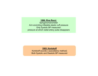


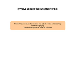
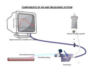
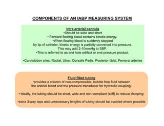
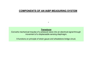
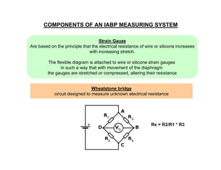


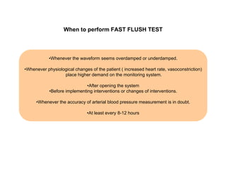

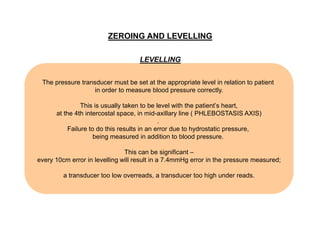


This document provides an overview of arterial blood pressure monitoring. It discusses the history and development of non-invasive blood pressure measurement techniques. It then focuses on the components, principles, and technical aspects of invasive arterial blood pressure monitoring using an intra-arterial catheter connected to a transducer system. Key points covered include the components of the measuring system, optimizing the system's natural frequency and damping, and the importance of zeroing and leveling the transducer.


