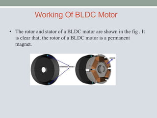
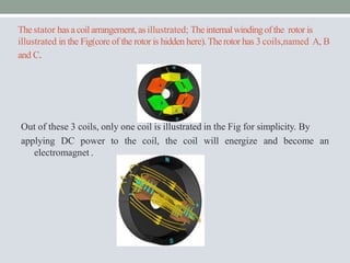
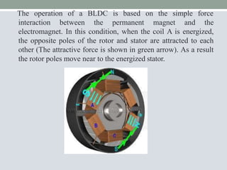
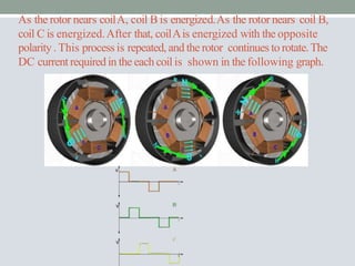
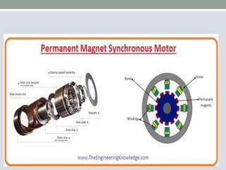
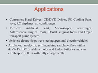
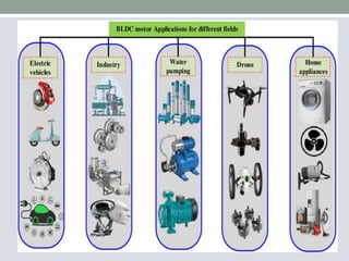
BLDC Motors
CONTENTS
1. PERMANENT MAGNET MOTOR
2. CONSTRUCTION AND OPERATION OF PM MOTOR
3. MAGNETIC CIRCUIT ANALYSIS
4. CHARACTERISTICS
5. BLDC VS BDC MOTORS
6. APPLICATION REQUIRED
PERMANENT MAGNET MOTOR
• A Permanent Magnet Motor, as the name suggests,
utilizes permanent magnets in the rotor to generate a
magnetic field, as opposed to using electromagnets.
These types of motors are often more efficient, have
higher power density, and are capable of more precise
control compared to motors that rely on electromagnets in
the rotor.
• So, a "Permanent Magnet Motor" can be considered as
an informal way of referring to a motor that utilizes
permanent magnets, and the most common type of such
motors is the Permanent Magnet Synchronous Motor
(PMSM). These motors have a wide range of applications,
including electric vehicles, industrial machinery, robotics,
renewable energy systems, and more.
EVOLUTION
CONVENTIONAL DC MOTOR
PERMANENT MAGNET DC MOTOR (PMDC)
BRUSHLESS PERMANENT DC MOTOR (BLPMDC)
Conventional DC Motors
• Converts electrical energy to mechanical energy
• Principle- When a current carrying conductor placed in a
magnetic field experiences a force
• Stator is made up of forced steel with inward projected poles
and poles carry field windings and rotor is of silicon steel
stampings
Brushed DC motor
COIL
BRUSH
Permanent magnet DC motor
• Construction of PMDC is similar to conventional dc motor
• Stator poles are replaced by suitable permanent magnets
• No need to have field windings .
Brushless Permanent Magnet DC
Motor
• Brushless DC electric motor also known as electronically commutated
motors (ECMs, EC motors) .
• The stator consists of several coils which current is led through Creating a
magnetic field that makes the rotor turns .
PMBLDC Motor
Construction of BLDC
• It consist of two parts mainly stator & rotor
Stator
 Stator is made up of silicon steel stampings with slots.
 The slots are accomodated armature windings.
 This winding is wound with specified no.of
poles(even number).
 This winding connected a dc supply through a power
electronic switching circuits ( inverter circuits) .
Rotor
 Rotor is of permanent magnet
 no of poles on rotor is same as that of stator
 Rotor shaft carries a RPS (Rotor position sensor) and it
provides information about the position of shaft at any instant
to the controller which sends signal to the electronic
commutator .
 The electronic commutator function is same as that of
mechanical commutator in DC motor
BLDC Motor Stator
BLDC Motor Rotors
Working Of BLDC Motor
• The rotor and stator of a BLDC motor are shown in the fig . It
is clear that, the rotor of a BLDC motor is a permanent
magnet.
Thestator hasacoilarrangement,asillustrated; Theinternalwindingofthe rotor is
illustrated in the Fig(core of the rotor is hidden here).Therotor has 3 coils,named A, B
and C.
Out of these 3 coils, only one coil is illustrated in the Fig for simplicity. By
applying DC power to the coil, the coil will energize and become an
electromagnet .
The operation of a BLDC is based on the simple force
interaction between the permanent magnet and the
electromagnet. In this condition, when the coil A is energized,
the opposite poles of the rotor and stator are attracted to each
other (The attractive force is shown in green arrow). As a result
the rotor poles move near to the energized stator.
As the rotor nears coilA, coil B is energized.As the rotor nears coil B,
coil C is energized.After that, coilAis energized with the opposite
polarity . This process is repeated, and the rotor continues to rotate.The
DC current requiredin the each coil is shown in the following graph.
Improving The BLDC Performance
Unlike a brushed DC motor, the commutation of BLDC
motor is controlled electronically.
It is important to know the rotor position in order
to understand which winding will be energized
following the energizing sequence.
Rotor position is sensed by different ways one
of which is :
1) Hall sensors
Hall Sensors
When a magnetic field applied to a system with
electric current a hall voltage Perpendicular to the
field and to current is generated.This was discovered
by Edwin Hall in 1879.
COMPARISON BETWEEN BDC
AND BLDC
PERMANENT MAGNET
SYNCHRONOUS MOTOR
• A PMSM (Permanent Magnet Synchronous Motor) is a type of
synchronous electric motor that uses permanent magnets
embedded in the rotor to create a magnetic field. This type of
motor is widely used in various applications due to its
efficiency, high power density, and precise control capabilities.
• Key features of PMSM motors include:
1. Permanent Magnets
2. High Efficiency
3. Precise Control
4. Wide Range of Applications
5. Regenerative Braking
6. Low Maintenance
Advantages
• Increased Reliability & Efficiency
• Longer Life
• Elimination of Sparks from Commutator
• Reduced Friction
• Faster Rate of Voltage & Current
Disadvantages
• Requires Complex Drive Circuitry
• Requires additional Sensors
• Higher Cost
• Some designs require manual labor
(Hand wound Stator Coils)
Applications
• Consumer: Hard Drives, CD/DVD Drives, PC Cooling Fans,
toys, RC airplanes, air conditioners
• Medical: Artificial heart, Microscopes, centrifuges,
Arthroscopic surgical tools, Dental surgical tools and Organ
transport pump system.
• Vehicles: electronic power steering ,personal electric vehicles
• Airplanes: an electric self launching sailplane, flies with a
42kW DC/DC brushless motor and Li-Ion batteries and can
climb up to 3000m with fully charged cells
THANK YOU

BLDC 11 (2).pptx

  • 1.
  • 2.
    CONTENTS 1. PERMANENT MAGNETMOTOR 2. CONSTRUCTION AND OPERATION OF PM MOTOR 3. MAGNETIC CIRCUIT ANALYSIS 4. CHARACTERISTICS 5. BLDC VS BDC MOTORS 6. APPLICATION REQUIRED
  • 3.
    PERMANENT MAGNET MOTOR •A Permanent Magnet Motor, as the name suggests, utilizes permanent magnets in the rotor to generate a magnetic field, as opposed to using electromagnets. These types of motors are often more efficient, have higher power density, and are capable of more precise control compared to motors that rely on electromagnets in the rotor. • So, a "Permanent Magnet Motor" can be considered as an informal way of referring to a motor that utilizes permanent magnets, and the most common type of such motors is the Permanent Magnet Synchronous Motor (PMSM). These motors have a wide range of applications, including electric vehicles, industrial machinery, robotics, renewable energy systems, and more.
  • 4.
    EVOLUTION CONVENTIONAL DC MOTOR PERMANENTMAGNET DC MOTOR (PMDC) BRUSHLESS PERMANENT DC MOTOR (BLPMDC)
  • 5.
    Conventional DC Motors •Converts electrical energy to mechanical energy • Principle- When a current carrying conductor placed in a magnetic field experiences a force • Stator is made up of forced steel with inward projected poles and poles carry field windings and rotor is of silicon steel stampings
  • 6.
  • 7.
    Permanent magnet DCmotor • Construction of PMDC is similar to conventional dc motor • Stator poles are replaced by suitable permanent magnets • No need to have field windings .
  • 8.
    Brushless Permanent MagnetDC Motor • Brushless DC electric motor also known as electronically commutated motors (ECMs, EC motors) . • The stator consists of several coils which current is led through Creating a magnetic field that makes the rotor turns .
  • 9.
  • 10.
    Construction of BLDC •It consist of two parts mainly stator & rotor Stator  Stator is made up of silicon steel stampings with slots.  The slots are accomodated armature windings.  This winding is wound with specified no.of poles(even number).  This winding connected a dc supply through a power electronic switching circuits ( inverter circuits) .
  • 11.
    Rotor  Rotor isof permanent magnet  no of poles on rotor is same as that of stator  Rotor shaft carries a RPS (Rotor position sensor) and it provides information about the position of shaft at any instant to the controller which sends signal to the electronic commutator .  The electronic commutator function is same as that of mechanical commutator in DC motor
  • 12.
  • 13.
  • 14.
    Working Of BLDCMotor • The rotor and stator of a BLDC motor are shown in the fig . It is clear that, the rotor of a BLDC motor is a permanent magnet.
  • 15.
    Thestator hasacoilarrangement,asillustrated; Theinternalwindingoftherotor is illustrated in the Fig(core of the rotor is hidden here).Therotor has 3 coils,named A, B and C. Out of these 3 coils, only one coil is illustrated in the Fig for simplicity. By applying DC power to the coil, the coil will energize and become an electromagnet .
  • 16.
    The operation ofa BLDC is based on the simple force interaction between the permanent magnet and the electromagnet. In this condition, when the coil A is energized, the opposite poles of the rotor and stator are attracted to each other (The attractive force is shown in green arrow). As a result the rotor poles move near to the energized stator.
  • 17.
    As the rotornears coilA, coil B is energized.As the rotor nears coil B, coil C is energized.After that, coilAis energized with the opposite polarity . This process is repeated, and the rotor continues to rotate.The DC current requiredin the each coil is shown in the following graph.
  • 18.
    Improving The BLDCPerformance Unlike a brushed DC motor, the commutation of BLDC motor is controlled electronically. It is important to know the rotor position in order to understand which winding will be energized following the energizing sequence. Rotor position is sensed by different ways one of which is : 1) Hall sensors
  • 19.
    Hall Sensors When amagnetic field applied to a system with electric current a hall voltage Perpendicular to the field and to current is generated.This was discovered by Edwin Hall in 1879.
  • 20.
  • 21.
    PERMANENT MAGNET SYNCHRONOUS MOTOR •A PMSM (Permanent Magnet Synchronous Motor) is a type of synchronous electric motor that uses permanent magnets embedded in the rotor to create a magnetic field. This type of motor is widely used in various applications due to its efficiency, high power density, and precise control capabilities. • Key features of PMSM motors include: 1. Permanent Magnets 2. High Efficiency 3. Precise Control 4. Wide Range of Applications 5. Regenerative Braking 6. Low Maintenance
  • 23.
    Advantages • Increased Reliability& Efficiency • Longer Life • Elimination of Sparks from Commutator • Reduced Friction • Faster Rate of Voltage & Current
  • 24.
    Disadvantages • Requires ComplexDrive Circuitry • Requires additional Sensors • Higher Cost • Some designs require manual labor (Hand wound Stator Coils)
  • 25.
    Applications • Consumer: HardDrives, CD/DVD Drives, PC Cooling Fans, toys, RC airplanes, air conditioners • Medical: Artificial heart, Microscopes, centrifuges, Arthroscopic surgical tools, Dental surgical tools and Organ transport pump system. • Vehicles: electronic power steering ,personal electric vehicles • Airplanes: an electric self launching sailplane, flies with a 42kW DC/DC brushless motor and Li-Ion batteries and can climb up to 3000m with fully charged cells
  • 27.