In this day and age of automated computer control valve sizing, the logic and theories behind it are invisible. In his presentation, Al Holton of Allagash Valve & Controls will look at the basic principles that apply and how they affect the application and installation of a wide range of control valve types. He will also review the reasoning behind valve type selection.
Basic Fluid Dynamics - Control Valves Brannon Gant
Setpoint Integrated Solutions is a industry leader in providing control valve solutions across industry segments.
Brannon Gant - Regional Sales Manager
Safety is the most important factor in designing a process system. Some undesired conditions might happen leading to damage in a system. Control systems might be installed to prevent such conditions, but a second safety device is also needed. One kind of safety device which is commonly used in the processing industry is the relief valve. A relief valve is a type of valve to control or limit the pressure in a system by allowing the pressurised fluid to flow out from the system.
Multiphase Flow Performance in Piping SystemsChrisJAlexisJr
Multiphase flow refers to the simultaneous flow of more than one fluid phase. It can be found in various places however it is most prevalent in the petroleum engineering field. This phenomenon brings about a major problem of pressure loss in the petroleum industry and results in a loss in production. Multiphase flow has been studied for years but there are few universally accepted solutions to calculate pressure drop. To accomplish this study, we used peer-review journals and articles in order to determine the flow regimes and characteristics of the different pipe orientations. This allowed us to determine the pressure drop calculations which were best suited for our study. We used a system that was designed with different pipe orientations that are found in the petroleum field and simulated the different flow regimes. Doing so allowed us to perform the calculations using two different pipe sizes; 1 inch and 1.5 inches. The results from the calculations showed that the pressure drop in the small pipe was greater than that of the bigger pipe.
Electrical Submersible Pump (ESP) is one of artificial lift methods that used widely in oil industry . In this presentation i showed the components of ESP and installation of it by using PIPESIM (schlumberger software )
Paul J. Boudreaux Consider a Mixed Analog/Digital/MEMsssusercf6d0e
Heat spreaders with high K values attached to the chip can help alleviate lateral DT problems. Placing the system or components into a forced isothermal environment also reduces DT, dT/dt and CTE related problems. Severing the thermomechanical heat path reduces or eliminates shock and vibration from entering the system while reducing weight.
Apart from TDMA, there are other iterative methods for solving the
system of equations which are faster. Unlike TDMA, which solves
the problem line by line, these iterative methods solves all
equations simultaneously. As a result these methods are faster than
TDMA. Some of the fast iterative methods are
1) SIP (strongly implicit procedure)
2) MSIP (modified SIP)
3) CG (Conjugate gradient method)
4) BiCGSTAB (bi-conjugate gradient stabilized method)
CG method is used for solving linear systems of equations which
have a symmetric coefficient matrix. All other methods mentioned
above are used for systems of equations involving non-symmetric
coefficient matrices.
must be set up at each nodal point.
We obtain a system of linear algebraic equations
Solve the system for values
Use any matrix solution method.
e.g. Tri-diagonal matrix algorithm (see textbook)
or: Gauss Seidel iteration method.
The convection of a scalar variable depends on the
magnitude and direction of the local velocity field.
How to find flow field?
Momentum equations can be derived from the Both sides of the equation contains temperatures at the new time step,
and a system of algebraic equations must be solved at each time level
is unconditionally stable for any Δt
is only first order accurate in time
small time steps are needed to ensure accuracy of results
The understanding of two-phase flow and heat transfer
with phase change in minichannels is needed for the design and
optimization of heat exchangers and other industrial
applications. In this study a three-dimensional numerical model
has been developed to predict filmwise condensation heat
transfer inside a rectangular minichannel. The Volume of Fluid
(VOF) method is used to track the vapor-liquid interface. The
modified High Resolution Interface Capture (HRIC) scheme is
employed to keep the interface sharp. The governing equations
and the VOF equation with relevant source terms for
condensation are solved. The surface tension is taken into
account in the modeling and it is evaluated by the Continuum
Surface Force (CSF) approach. The simulation is performed
using the CFD software package, ANSYS FLUENT, and an inhouse
developed code. This in-house code is specifically
developed to calculate the source terms associated with phase
change. These terms are deduced from Hertz-Knudsen equation
based on the kinetic gas theory. The numerical results are
validated with data obtained from the open literature. The
standard k-ω model is applied to model the turbulence through
both the liquid and vapor phase. The numerical results show
that surface tension plays an important role in the condensation
heat transfer process. Heat transfer enhancement is obtained
due to the presence of the corners. The surface tension pulls the
liquid towards the corners and reduces the average thermal
resistance in the cross section.
The role of boilers and heat recovery steam generators (HRSGs) in the industrial
economy has been profound. Boilers form the backbone of power plants,
cogeneration systems, and combined cycle plants. There are few process
plants, refineries, chemical plants, or electric utilities that do not have a steam
plant. Steam is the most convenient working fluid for industrial processing,
heating, chilling, and power generation applications. Fossil fuels will continue to
be the dominant energy providers for years to come.
This book is about steam generators, HRSGs, and related systems. There
are several excellent books on steam generation and boilers, and each has been
successful in emphasizing certain aspects of boilers and related topics such as
mechanical design details, metallurgy, corrosion, constructional aspects, maintenance,
or operational issues. This book is aimed at providing a different
perspective on steam generators and is biased toward thermal and process
design aspects of package boilers and HRSGs. (The terms ‘‘waste heat boiler’’
and ‘‘HRSG’’ are used in the same context.) My emphasis on thermal engineering
aspects of steam generators reinforced by hundreds of worked-out real-life
examples pertaining to boilers, HRSGs, and related systems will be of interest
to engineers involved in a broad field of steam generator–related activities such as
consulting, design, performance evaluation, and operation. During the last three decades I have had the opportunity to design hundreds
of package boilers and several hundred waste heat boilers that are in operation in
the U.S. and abroad. Based on my experience in reviewing numerous specifications
of boilers and HRSGs, I feel that consultants, plant engineers, contractors,
and decision makers involved in planning and developing steam plants often do
not appreciate some of the important and subtle aspects of design and performance
of steam generators.
Among the leading causes of discomfort in an air conditioned environment we can detected:
• too high air flow, generating drafts;
• uneven distribution of the incoming air volume;
• non homogeneous temperature distribution in the room.
To avoid these drawbacks, it is necessary to generate a proper diffusion of the air, which guarantees the right
temperature, relative humidity, speed and purity corresponding to the environmental comfort desired.
The Eurapo UCS cassette units are able to give a balanced response to all these needs: the outlet air is spread
like a classic four-way ceiling diffuser, with distribution from two to four orthogonal directions.
This system takes full advantage of the Coanda effect, greatly reducing the air flow direct to people, with
positive consequences for their comfort.
Hybrid optimization of pumped hydro system and solar- Engr. Abdul-Azeez.pdffxintegritypublishin
Advancements in technology unveil a myriad of electrical and electronic breakthroughs geared towards efficiently harnessing limited resources to meet human energy demands. The optimization of hybrid solar PV panels and pumped hydro energy supply systems plays a pivotal role in utilizing natural resources effectively. This initiative not only benefits humanity but also fosters environmental sustainability. The study investigated the design optimization of these hybrid systems, focusing on understanding solar radiation patterns, identifying geographical influences on solar radiation, formulating a mathematical model for system optimization, and determining the optimal configuration of PV panels and pumped hydro storage. Through a comparative analysis approach and eight weeks of data collection, the study addressed key research questions related to solar radiation patterns and optimal system design. The findings highlighted regions with heightened solar radiation levels, showcasing substantial potential for power generation and emphasizing the system's efficiency. Optimizing system design significantly boosted power generation, promoted renewable energy utilization, and enhanced energy storage capacity. The study underscored the benefits of optimizing hybrid solar PV panels and pumped hydro energy supply systems for sustainable energy usage. Optimizing the design of solar PV panels and pumped hydro energy supply systems as examined across diverse climatic conditions in a developing country, not only enhances power generation but also improves the integration of renewable energy sources and boosts energy storage capacities, particularly beneficial for less economically prosperous regions. Additionally, the study provides valuable insights for advancing energy research in economically viable areas. Recommendations included conducting site-specific assessments, utilizing advanced modeling tools, implementing regular maintenance protocols, and enhancing communication among system components.
NO1 Uk best vashikaran specialist in delhi vashikaran baba near me online vas...Amil Baba Dawood bangali
Contact with Dawood Bhai Just call on +92322-6382012 and we'll help you. We'll solve all your problems within 12 to 24 hours and with 101% guarantee and with astrology systematic. If you want to take any personal or professional advice then also you can call us on +92322-6382012 , ONLINE LOVE PROBLEM & Other all types of Daily Life Problem's.Then CALL or WHATSAPP us on +92322-6382012 and Get all these problems solutions here by Amil Baba DAWOOD BANGALI
#vashikaranspecialist #astrologer #palmistry #amliyaat #taweez #manpasandshadi #horoscope #spiritual #lovelife #lovespell #marriagespell#aamilbabainpakistan #amilbabainkarachi #powerfullblackmagicspell #kalajadumantarspecialist #realamilbaba #AmilbabainPakistan #astrologerincanada #astrologerindubai #lovespellsmaster #kalajaduspecialist #lovespellsthatwork #aamilbabainlahore#blackmagicformarriage #aamilbaba #kalajadu #kalailam #taweez #wazifaexpert #jadumantar #vashikaranspecialist #astrologer #palmistry #amliyaat #taweez #manpasandshadi #horoscope #spiritual #lovelife #lovespell #marriagespell#aamilbabainpakistan #amilbabainkarachi #powerfullblackmagicspell #kalajadumantarspecialist #realamilbaba #AmilbabainPakistan #astrologerincanada #astrologerindubai #lovespellsmaster #kalajaduspecialist #lovespellsthatwork #aamilbabainlahore #blackmagicforlove #blackmagicformarriage #aamilbaba #kalajadu #kalailam #taweez #wazifaexpert #jadumantar #vashikaranspecialist #astrologer #palmistry #amliyaat #taweez #manpasandshadi #horoscope #spiritual #lovelife #lovespell #marriagespell#aamilbabainpakistan #amilbabainkarachi #powerfullblackmagicspell #kalajadumantarspecialist #realamilbaba #AmilbabainPakistan #astrologerincanada #astrologerindubai #lovespellsmaster #kalajaduspecialist #lovespellsthatwork #aamilbabainlahore #Amilbabainuk #amilbabainspain #amilbabaindubai #Amilbabainnorway #amilbabainkrachi #amilbabainlahore #amilbabaingujranwalan #amilbabainislamabad
Explore the innovative world of trenchless pipe repair with our comprehensive guide, "The Benefits and Techniques of Trenchless Pipe Repair." This document delves into the modern methods of repairing underground pipes without the need for extensive excavation, highlighting the numerous advantages and the latest techniques used in the industry.
Learn about the cost savings, reduced environmental impact, and minimal disruption associated with trenchless technology. Discover detailed explanations of popular techniques such as pipe bursting, cured-in-place pipe (CIPP) lining, and directional drilling. Understand how these methods can be applied to various types of infrastructure, from residential plumbing to large-scale municipal systems.
Ideal for homeowners, contractors, engineers, and anyone interested in modern plumbing solutions, this guide provides valuable insights into why trenchless pipe repair is becoming the preferred choice for pipe rehabilitation. Stay informed about the latest advancements and best practices in the field.
Courier management system project report.pdfKamal Acharya
It is now-a-days very important for the people to send or receive articles like imported furniture, electronic items, gifts, business goods and the like. People depend vastly on different transport systems which mostly use the manual way of receiving and delivering the articles. There is no way to track the articles till they are received and there is no way to let the customer know what happened in transit, once he booked some articles. In such a situation, we need a system which completely computerizes the cargo activities including time to time tracking of the articles sent. This need is fulfilled by Courier Management System software which is online software for the cargo management people that enables them to receive the goods from a source and send them to a required destination and track their status from time to time.
Sachpazis:Terzaghi Bearing Capacity Estimation in simple terms with Calculati...Dr.Costas Sachpazis
Terzaghi's soil bearing capacity theory, developed by Karl Terzaghi, is a fundamental principle in geotechnical engineering used to determine the bearing capacity of shallow foundations. This theory provides a method to calculate the ultimate bearing capacity of soil, which is the maximum load per unit area that the soil can support without undergoing shear failure. The Calculation HTML Code included.
Cosmetic shop management system project report.pdfKamal Acharya
Buying new cosmetic products is difficult. It can even be scary for those who have sensitive skin and are prone to skin trouble. The information needed to alleviate this problem is on the back of each product, but it's thought to interpret those ingredient lists unless you have a background in chemistry.
Instead of buying and hoping for the best, we can use data science to help us predict which products may be good fits for us. It includes various function programs to do the above mentioned tasks.
Data file handling has been effectively used in the program.
The automated cosmetic shop management system should deal with the automation of general workflow and administration process of the shop. The main processes of the system focus on customer's request where the system is able to search the most appropriate products and deliver it to the customers. It should help the employees to quickly identify the list of cosmetic product that have reached the minimum quantity and also keep a track of expired date for each cosmetic product. It should help the employees to find the rack number in which the product is placed.It is also Faster and more efficient way.
Quality defects in TMT Bars, Possible causes and Potential Solutions.PrashantGoswami42
Maintaining high-quality standards in the production of TMT bars is crucial for ensuring structural integrity in construction. Addressing common defects through careful monitoring, standardized processes, and advanced technology can significantly improve the quality of TMT bars. Continuous training and adherence to quality control measures will also play a pivotal role in minimizing these defects.
Industrial Training at Shahjalal Fertilizer Company Limited (SFCL)MdTanvirMahtab2
This presentation is about the working procedure of Shahjalal Fertilizer Company Limited (SFCL). A Govt. owned Company of Bangladesh Chemical Industries Corporation under Ministry of Industries.
Design and Analysis of Algorithms-DP,Backtracking,Graphs,B&B
Bhmn 35002-camflex-iom-19538 e-0820-english
1. Baker Hughes Data Classification: Public
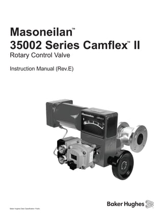
Masoneilan™
35002 Series Camflex™
II
Rotary Control Valve
Instruction Manual (Rev.E)
2. b | Baker Hughes Copyright 2020 Baker Hughes Company. All rights reserved.
THESE INSTRUCTIONS PROVIDE THE CUSTOMER/OPERATOR WITH IMPORTANT PROJECT-
SPECIFIC REFERENCE INFORMATION IN ADDITION TO THE CUSTOMER/OPERATOR’S
NORMAL OPERATION AND MAINTENANCE PROCEDURES. SINCE OPERATION AND
MAINTENANCE PHILOSOPHIES VARY, BAKER HUGHES (AND ITS SUBSIDIARIES AND
AFFILIATES) DOES NOT ATTEMPT TO DICTATE SPECIFIC PROCEDURES, BUT TO PROVIDE
BASIC LIMITATIONS AND REQUIREMENTS CREATED BY THE TYPE OF EQUIPMENT
PROVIDED.
THESE INSTRUCTIONS ASSUME THAT OPERATORS ALREADY HAVE A GENERAL
UNDERSTANDING OF THE REQUIREMENTS FOR SAFE OPERATION OF MECHANICAL AND
ELECTRICAL EQUIPMENT IN POTENTIALLY HAZARDOUS ENVIRONMENTS. THEREFORE,
THESE INSTRUCTIONS SHOULD BE INTERPRETED AND APPLIED IN CONJUNCTION WITH
THE SAFETY RULES AND REGULATIONS APPLICABLE AT THE SITE AND THE PARTICULAR
REQUIREMENTS FOR OPERATION OF OTHER EQUIPMENT AT THE SITE.
THESE INSTRUCTIONS DO NOT PURPORT TO COVER ALL DETAILS OR VARIATIONS IN
EQUIPMENT NOR TO PROVIDE FOR EVERY POSSIBLE CONTINGENCY TO BE MET IN
CONNECTION WITH INSTALLATION, OPERATION OR MAINTENANCE. SHOULD FURTHER
INFORMATION BE DESIRED OR SHOULD PARTICULAR PROBLEMS ARISE WHICH ARE NOT
COVERED SUFFICIENTLY FOR THE CUSTOMER/OPERATOR'S PURPOSES THE MATTER
SHOULD BE REFERRED TO BAKER HUGHES.
THE RIGHTS, OBLIGATIONS AND LIABILITIES OF BAKER HUGHES AND THE CUSTOMER/
OPERATOR ARE STRICTLY LIMITED TO THOSE EXPRESSLY PROVIDED IN THE CONTRACT
RELATING TO THE SUPPLY OF THE EQUIPMENT. NO ADDITIONAL REPRESENTATIONS OR
WARRANTIES BY BAKER HUGHES REGARDING THE EQUIPMENT OR ITS USE ARE GIVEN
OR IMPLIED BY THE ISSUE OF THESE INSTRUCTIONS.
THESE INSTRUCTIONS ARE FURNISHED TO THE CUSTOMER/OPERATOR SOLELY TO
ASSIST IN THE INSTALLATION, TESTING, OPERATION, AND/OR MAINTENANCE OF THE
EQUIPMENT DESCRIBED. THIS DOCUMENT SHALL NOT BE REPRODUCED IN WHOLE OR IN
PART WITHOUT THE WRITTEN APPROVAL OF BAKER HUGHES.
3. Masoneilan 35002 Series Camflex II Instruction Manual | c
Copyright 2020 Baker Hughes Company. All rights reserved.
Table Of Contents
Safety Information......................................................................................................................1
About this Manual......................................................................................................................1
Warranty......................................................................................................................................1
1. Introduction.............................................................................................................................2
2. General....................................................................................................................................2
3. Principle Of Operation...........................................................................................................2
4. Unpacking...............................................................................................................................3
5. Installation..............................................................................................................................3
6. Air Supply Piping....................................................................................................................4
7. Placing In Service...................................................................................................................4
8. Disassembly...........................................................................................................................4
8.1 Actuator Removal from Body S/A.
.....................................................................................4
8.2 Actuator Complete Disassembly.......................................................................................5
8.3 Valve Body........................................................................................................................5
9. Maintenance............................................................................................................................7
9.1 Spring Diaphragm Replacement.......................................................................................7
9.2 Body S/A Internal Parts.....................................................................................................8
9.3 Yoke Assembly..................................................................................................................9
10. Reassembly Procedures......................................................................................................9
10.1 Spring Diaphragm Actuator.............................................................................................9
10.2 Spring Diaphragm Actuator on Body S/A........................................................................9
10.3 Handwheel Reassembly.................................................................................................10
10.4 Limit Stop Reassembly...................................................................................................10
10.5 Valve Body Reassembly.................................................................................................10
10.6 Seat Ring Alignment.......................................................................................................11
10.7 DVD Plate Reassembly..................................................................................................12
11. Actuator Stem Adjustment...................................................................................................12
12. Changing Body Position......................................................................................................13
13. Changing Actuator Action...................................................................................................14
14. Manual Actuator Option.......................................................................................................15
14.1 Disassembly Procedure..................................................................................................15
14.2 Maintenance...................................................................................................................15
14.3 Reassembly Procedure.
..................................................................................................15
4. 1 | Baker Hughes Copyright 2020 Baker Hughes Company. All rights reserved.
Safety Information
Important - Please read before installation
These instructions contain DANGER, WARNING, and CAUTION
labels, where necessary, to alert you to safety related or other
important information. Read the instructions carefully before
installing and maintaining your control valve. DANGER and
WARNING hazards are related to personal injury. CAUTION
hazards involve equipment or property damage. Operation
of damaged equipment can, under certain operational
conditions, result in degraded process system performance
that can lead to injury or death. Total compliance with all
DANGER, WARNING, and CAUTION notices is required for
safe operation.
This is the safety alert symbol. It alerts you to potential personal
injury hazards. Obey all safety messages that follow this symbol
to avoid possible injury or death.
Indicates a potentially hazardous situation which, if not avoided,
could result in death or serious injury.
Indicates a potentially hazardous situation which, if not avoided,
could result in serious injury.
Indicates a potentially hazardous situation which, if not avoided,
could result in minor or moderate injury.
When used without the safety alert symbol, indicates a
potentially hazardous situation which, if not avoided, could result
in property damage.
Note: Indicates important facts and conditions.
About this Manual
• The information in this manual is subject to change without
prior notice.
• The information contained in this manual, in whole or part,
shall not be transcribed or copied without Baker Hughes’s
written permission.
•
Please report any errors or questions about the information
in this manual to your local supplier.
•
These instructions are written specifically for the 35002
Series Camflex II, and do not apply for other valves outside
of this product line.
Useful Period
The current estimated useful life period for the 35002 Series
Camflex II is 25+ years. To maximize the useful life of the product,
it is essential to conduct annual inspections, routine maintenance
and ensure proper installation to avoid any unintended stresses
on the product. The specific operating conditions will also impact
the useful life of the product. Consult the factory for guidance on
specific applications if required prior to installation.
Warranty
Items sold by Baker Hughes are warranted to be free from defects
in materials and workmanship for a period of one year from the
date of shipment provided said items are used according to
Baker Hughes recommended usages. Baker Hughes reserves
the right to discontinue manufacture of any product or change
product materials, design or specifications without notice.
Note: Prior to installation:
• The valve must be installed, put into service and maintained
by qualified and competent professionals who have
undergone suitable training.
•
All surrounding pipe lines must be thoroughly flushed to
ensure all entrained debris has been removed from the
system.
•
Under certain operating conditions, the use of damaged
equipment could cause a degradation of the performance
of the system which may lead to personal injury or death.
•
Changes to specifications, structure, and components used
may not lead to the revision of this manual unless such
changes affect the function and performance of the product.
5. Masoneilan 35002 Series Camflex II Instruction Manual | 2
Copyright 2020 Baker Hughes Company. All rights reserved.
1. Introduction
The following instructions are designed to assist maintenance
personnel in performing most of the maintenance required on the
Camflex II valve and if followed carefully will reduce maintenance
time.
Baker Hughes has highly skilled Service Engineers available for
start-up, maintenance and repair of our valves and component
parts. In addition, regularly scheduled training programs are
conducted to train customer service and instrumentation
personnel in the operation, maintenance and application of our
control valves and instruments. Arrangements for these services
can be made through Baker Hughes products representative
or district office. When performing maintenance use only
Masoneilan replacement parts. Parts are obtainable through
your local representative or district office. When ordering parts
always include MODEL and SERIAL NUMBER of the unit
being repaired.
2. General
These installation and maintenance instructions apply to 1"
through 12" sizes (DN 25 through 300 sizes), all available
ratings, and pneumatic actuators. The model number, size and
rating of the valve are shown on the serial plate. Refer to Figure
1 to identify the valve model.
3. Principle of Operation
The concept of the Camflex II valve is based on an eccentrically
rotating spherical plug contained in a free flow body design. The
plug seating surface is joined by flexible arms to a hub which
slides onto a rotating shaft. The plug is free to center itself along
the axis of the shaft. A positive seal between plug and seat is
achieved by elastic deformation of the plug arms. The chamfered
seat ring is fixed in the valve body by a threaded retainer.
The plug and shaft are rotated through an angle of 50° by a lever
linked to a powerful spring-opposed rolling diaphragm actuator.
The solid disk-type handwheel and locking hex nut, optional, are
mounted on the yoke, opposite the actuator and may be used
to manually operate the valve or as a limit stop. A threaded hole
in the opposite side of the yoke is plugged but can be equipped
with an optional cap screw and locknut, which may be inserted
as a limit stop in the other direction, or in combination with the
handwheel to lock the valve in a selected position.
Figure 1
35002 Series Numbering System
Trim Type Design
1st 2nd
Actuator Type
1.
Parallel to
pipeline, valve
closes on stem
extension.
2.
Parallel to
pipeline, valve
opens on stem
extension.
3.
Perpendicular
to pipeline,
valve closes on
stem extension.
4.
Perpendicular
to pipeline,
valve opens on
stem extension.
5.
Parallel to
pipeline, valve
closes on stem
extension.
6.
Parallel to
pipeline, valve
opens on stem
extension.
7.
Perpendicular
to pipeline,
valve closes on
stem extension.
8.
Perpendicular
to pipeline,
valve opens on
stem extension.
Actuator Mounting
(see guide on page 3)
Body
Series
35 SB
(optional
separable
bonnet)
GR
(optional
Globe
Replacement
face to face)
2
Design
Series
1. Metal Seat
2. Soft Seat
3.
Metal Seat
w/ Differen-
tial Velocity
Trim
4.
Soft Seat w/
Differential
Velocity Trim
20 Manual Actuator
35 Spring-opposed
rolling-dia-
phragm
4th
3rd 5th
2
2nd
5
1st
3
6. 3 | Baker Hughes Copyright 2020 Baker Hughes Company. All rights reserved.
Note: The handwheel on Camflex II is designed to be used
for emergency action only.
The actuator is generally mounted with air-loading to counter
the dynamic torque on the plug. In Figure 2 the flow direction
tends to open the plug and the actuator is oriented to close it with
increasing air pressure. The actuator spring force assists plug
off-balance forces to open the valve on air failure. If the valve is
to close on air failure, the body would be turned around in the
line so that flow tends to close the plug and the actuator position
would be reversed.
The Camflex II valve has a modified linear flow characteristic,
which is the same in either flow direction. It can be easily
transformed to an equal percentage when equipping the
valve with a positioner 4700 series, 8000 series or SVI
Smart Valve Interface. Reduced TRIM factors 0.4 and 0.6
are available on all sizes. The flow capacity of a 0.4 factor
is 40% of the nominal capacity of the valve and it is 60%
for the 0.6 factor. Factors 0.1 and 0.2 are available on the
1 (DN 25) valve.
The ability of the Camflex II valve to handle a wide range of
process fluid temperatures is due to the long integrally cast
bonnet. This affords ample radiation surface to normalize the
packing temperature. Therefore, with self-lubricating TFE Aramid
fiber packing, the valve handles temperatures from -196°C to
+ 400°C (-321°F to +752°F). When insulating the valve, do not
insulate the valve bonnet (see Figure 3).
Figure 3
4. Unpacking
Care must be exercised when unpacking the valve to prevent
damage to the accessories and component parts. Should any
problems arise, contact your representative or district office.
Note: For ease of shipment and to prevent damage, valves
equipped with the spring diaphragm actuator are shipped
with the handwheel unassembled. Refer to Section 10.3 for
handwheel assembly procedures.
5. Installation
The Camflex II valve has been assembled at the factory in
accordance with specific instructions concerning flow direction
and actuator mode. The valve must be installed so that the
controlled substance will flow through the valve in the direction
indicated by the flow arrow (25), which is located on the upper
part of the valve bonnet. The valve actuator should be installed
so the actuator is above the centerline of the shaft. To install the
valve in the line, proceed as follows:
Any change in flow direction or actuator mode must be
accomplished as outlined in Sections 7 and 10 of this
instruction manual. Failure to follow these could result
in personal injury and equipment malfunction.
A.
Check the model number on the serial plate (56) against the
numbering System described in Figure 1 to determine the
valve mode.
B.
Clean piping and valve of all foreign material such as welding
chips, scale, oil, grease or dirt. Gasket surfaces should be
thoroughly cleaned to ensure leak proof connections.
C.
To allow for in-line inspection, maintenance or removal of
the valve without service interruption, provide a manually
operated stop valve on each side of the Camflex II valve with
a manually operated throttling valve mounted in the by-pass
line.
Figure 2
Plug
Seat Ring
Fluid Flow
Shaft
Guide Bushing
Flexible Arms
Guide Bushing
Air
Actuator
Lever
Handwheel
7. Masoneilan 35002 Series Camflex II Instruction Manual | 4
Copyright 2020 Baker Hughes Company. All rights reserved.
Note: If a flanged Camflex II is being installed and the
distance between flanges is established by ANSI or DIN,
spool pieces (spacers) are inserted between the line
flange and the valve body flange. Gaskets and valve
bolting are then installed and torqued using standard
flange and line bolting criteria.
D.
For flangeless valves, refer to Figure 23 and determine the
correct size and quantity of bolts to be used for the valve and
flange rating.
E.
If the valve is to be installed in a horizontal position, install
the lower flange bolting to provide a cradle, which will help
support the valve while installing the remaining bolts.
F. Place the valve in the line.
G. Select and install correct gaskets.
Note: Spiral wound gaskets, suitable for service
conditions are recommended.
H.
Insert remaining flange bolting ensuring that the bolts align
with the special bosses on the body, which assure the valve
is centered in the line and also prevent rotation.
Note: For certain flange standards, through bolting is
not possible because of the valve body neck or bonnet.
To accommodate flange bolting, guide arms with
threaded holes or slots are provided on the valve body
to receive flange bolts (refer to Figure 22).
I.
Tighten flange bolts evenly and firmly.
If the valve is to be insulated, do not insulate the
valve bonnet.
Note: If the valve is equipped with manual handwheel,
it may now be placed in service.
6. Air Supply Piping
Air is supplied to the actuator through the 1/4 NPT tapped
connection in the diaphragm case. Refer to Figure 14 to
determine the correct supply pressure and tubing size, then
connect air supply piping.
Do not exceed maximum air pressure indicated. Per-
sonal injury and equipment malfunction could result.
Note: When the valve is equipped with regulators or other
accessories supplied by Baker Hughes, only connections
to those accessories are required since the piping to the
actuator is connected at the factory. Some valves equipped
with electrical accessories will require appropriate wiring.
Refer to manufacturer’s instructions for correct wiring
information.
7. Placing in Service
With the valve properly installed in the line and all air or electrical
service connected, it is recommended that the valve be run
through one cycle to ensure proper functioning. Proceed as
follows:
A.
Back off the handwheel (53) so that it will not interfere with
the operation of the valve and tighten the handwheel lock
(52).
Note: If the valve is equipped with the optional limit stop
(77), it should also be backed off to prevent interference
with the operation of the valve.
B. Apply correct air pressure to the actuator.
Note: Valve should function smoothly and with
maximum pressure, the valve indicator (6) should show
full open or full close depending on valve mode.
C. Relieve air pressure and return valve to normal mode.
D. Gradually open process lines to place the valve in service.
E. Check for leaks. Repair as required.
Always ensure process pressure, air pressure and
electrical service are off and the valve is isolated and
relieved of pressure before performing maintenance
on the valve.
F.
If desired, the handwheel may be used as a limit stop. Set
in desired position and lock.
G. If the optional limit stop (77) is used, set and tighten locknut.
8. Disassembly
8.1
Actuator Removal From Body S/A
(Refer to Figures 16 and 17)
Maintenance required on the internal components of the valve
or re-orientation of the actuator and body, requires that the
actuator and yoke be removed from the valve. On the size 6,
7 and 9 actuators, for ease of handling and reassembly, it is
recommended that the spring barrel be removed from the yoke
and then the yoke separated from the valve body.
Prior to performing maintenance on the valve, isolate
the valve, vent the process pressure and shut off
supply and signal air lines to the actuator.
Note: If the valve will be reassembled in the same orientation,
it is recommended that the body to yoke orientation and the
actuator to yoke orientation be marked in relation to each
other. This will simplify reassembly.
A. If required, remove the valve from the line.
B.
Remove rear cover (29) and front cover (32) by removing
the two cover screws (30).
C.
Remove bottom cover (11) and spring barrel boss cover
(58).
8. 5 | Baker Hughes Copyright 2020 Baker Hughes Company. All rights reserved.
D.
Remove the adjustable indicator (88) by removing the two
screws (89).
E.
Loosen handwheel lock (52) and turn handwheel (53) so it
does not interfere with the movement of the lever (34).
Note: On valves supplied with the optional limit stop,
(Figure 17) loosen nut (78) and back off the limit stop
screw (77) so it will not interfere with the movement of
the lever (34).
F.
Connect an air line to the actuator supply port and using a
manual loading panel or regulated air supply, apply enough
air pressure to the actuator so the lever will move to an
intermediate position.
Do not exceed pressure listed in Figure 14 for actua-
tor used. Do not use handwheel to move the lever.
Note: If the valve is to be reassembled using the same
orientation, it is recommended that the yoke (33) and
lever (34) alignment, in the closed position, be marked
to simplify reassembly and alignment of the lever and
shaft to ensure proper valve functioning. See Figure 17.
G. Remove clevis pin clips (5).
H. Remove clevis pin (7).
I.
Relieve air pressure from actuator enabling clevis (35) to
disengage from lever (34).
Note: If the valve is equipped with a positioner, refer to
the appropriate positioner instruction for procedures
on cam or lever removal. Then proceed to step K.
J. Remove shaft cover (9) by removing cover screw (10).
Depending on the size and weight of the actuator. It
is recommended that proper lift and support proce-
dures be utilized when removing the spring barrel or
yoke.
K. Ensure spring barrel is properly supported.
L.
Loosen and remove cap screws (36) and lock washers (37),
then remove spring barrel (38).
M. Loosen lever capscrew (49).
N.
Loosen the stud nuts (94) and disengage the packing
flange.
O.
Loosen the stud nuts (27) to separate the actuator from the
body S/A.
Note: With body secure, grasp lever and yoke and
separate. Yoke, lever and packing flange are removed
at the same time. The yoke may have to be struck with
a soft face mallet to break it loose.
8.2 Actuator Complete Disassembly
The spring diaphragm actuator used on the Camflex II valve
was designed basically as a low cost non-replaceable item and
therefore disassembly is not recommended. However, in some
instances and for emergency purposes, disassembly may be
required. Proceed as follows.
A.
If the actuator is not removed from the body proceed to the
paragraph 9.1 A. to 9.1 L.
B.
Loosen locknut (46) then remove the clevis (35) and the
locknut (46).
C.
Loosen and remove capscrew (41) and remove dia-phragm
case (42) and diaphragm (40).
D.
Using a deep socket, loosen and remove lock nut (45) and
washer (44).
E.
Remove piston (43) and spring (39) and inspect all
components.
F. Proceed to section 10.2 for reassembly.
8.3
Valve Body (Refer to Figures 4
and 16)
Maintenance to the internal components required on the Camflex
II Valve can normally be easily determined since the seat ring
and plug can be seen once the valve is removed from the line.
Although it may be determined that the seat ring does not need
replacement, it must be noted that the new plug and seat ring
must be lapped, thus requiring the disassembly of the body. It is
recommended that both seat ring and plug be replaced if one or
the other is damaged due to service.
After the actuator has been removed from the body, dis-
assemble the valve using the following procedure:
Prior to performing maintenance on the valve, isolate
the valve and vent the process pressure.
A.
For 35002 SB (Separable Bonnet) versions, remove
bonnet nuts (104) and lift off bonnet (102) complete with
packing (17) and packing follower (15) from the body as an
assembly. Proceed to step D.
B. Remove packing follower (15).
C. Remove safety pin (16).
The purpose of the safety pin is to prevent the shaft
from being pushed out if the yoke is removed while
the valve is still pressurized. The internal compo-
nents of the valve cannot be removed without first
removing the safety pin.
D. Pull on the shaft (19) to remove it.
Note: Difficulty is sometimes encountered when
removing the shaft from the plug mainly due to an
excessive accumulation of deposits between the plug
splines and the shaft. Application of heat to the plug
shaft bore while using one of the following methods
will facilitate removal.
9. Masoneilan 35002 Series Camflex II Instruction Manual | 6
Copyright 2020 Baker Hughes Company. All rights reserved.
When using heating devices, ensure that proper
safety practices are observed. Such items as
the flammability and toxicity of the controlled
substance must be considered and proper
precautions taken.
If the shaft is not removed easily, replace the lever (34) on
the splined end of the shaft (19), tighten the lever capscrew
(49) and using a mallet, tap the lever (34) as close to the
shaft as possible and remove the shaft (19).
Note: If the shaft cannot be removed by tapping the
tightened lever, Figure 20 illustrates an alternative
method of removal. Using a pipe nipple of suitable
size and length and reversing the packing flange and
stud nuts as shown, the shaft may be jacked out of the
body. For larger valves, the use of an additional washer
and nipple to assist in holding the tightened lever is
recommended. The lever should be tightened at a point
where the hub on the lever is flush with the end of the
spline.
E.
The components which should come out with the shaft (19)
are: the packing (17), packing box ring (23 or 100), spacer
tube (20) and upper guide bushing (21).
Note: The spacer tube (20) and upper guide bushing
(21) may remain in the body. They should be removed.
The spacer tube (20) can only be removed by pulling
it out the bonnet end of the body. The upper guide
bushing (21) may be pushed through the body after
removing the plug or pulled through the bonnet end
of the body. On valves designed for use on slurry or
viscous service, the upper guide bushing has an inner
“O” ring (92) and an outer “O” ring (93) and the lower
guide bushing has inner “O” ring (95) and outer “O”
ring (96) (Refer to Figure 4).
92
93 21 22 96
95
Figure 4 - Optional “O” ring arrangement
F.
Remove the plug (4) through the end of the body opposite
the seat ring.
G. Remove the lower guide bushing (22).
Note: A groove is provided in the bushing for prying
out the bushing using a screwdriver. If the bushing
will be pried out it should be pried from two sides to
prevent jamming the bushing during removal. If the
bushing does not come out easily, fill the bushing with
grease, insert the shaft (19) into the valve insuring that
the machined portion of the shaft starts into the lower
guide bushing. Using a soft faced mallet, strike the
end of the shaft lightly until the bushing is pushed out
partially. Remove the shaft and complete removal of
the bushing by prying out using the groove provided.
Do not pry the bushing using the seat for
leverage. If the bushing cannot be easily
removed, proceed to section 8.3.1 and remove
the seat ring retainer and seat ring then remove
the bushing. Place a piece of soft stock (brass,
etc.) between the inner seat shoulder and prying
device to prevent damage to the seat sealing area
of the body.
8.3.1 Seat Ring Removal (Refer to Figure 16)
The following procedures outline the recommended method
for removing the seat ring retainer (3) with the use of retainer
wrenches. Baker Hughes manufactures and has available, for a
nominal price, seat ring retainer wrenches for the Camflex II, 1
through 4 (DN 25 through 100) sizes. It is highly recommended
that wrenches be purchased or fabricated to facilitate removal
and reassembly of the seat ring (2) since SPECIFIC TORQUES
MUST BE ACHIEVED to obtain tight shutoff and ensure proper
functioning of the valve.
Figure 5 shows the recommended materials, thickness and
method of construction along with specific dimensions to
facilitate construction.
A
A
B
WELDED
KEY
STOCK
3/16 STEEL PLATE
A = O.D. Seat Ring Retainer
B = Width of slot in Retainer
C = I.D. of Seat Ring Retainer
WELDED
HEX NUT
C
Figure 5
A.
Secure the valve body in a vise or appropriate holding
device with the seat ring facing up.
Care must be taken to avoid damage to the gasket
face on the valve body.
B. Place retainer wrench so it engages retainer lugs.
C.
Engage the retainer wrench with an impact wrench or
suitable wrench and loosen, then remove retainer (3) by
turning counterclockwise.
Note: The Camflex GR body constructions will require
an extension to reach the retainer, due to the longer
body pattern.
D. Lift out seat ring.
10. 7 | Baker Hughes Copyright 2020 Baker Hughes Company. All rights reserved.
Note: In an emergency, drifts may be used to remove
the seat ring retainer. However, two drifts should be
used and placed in the slots 180° apart and struck
simultaneously.
8.3.2 DVD Removal (Refer to Figure 16)
In case of Camflex with the DVD option, model number 35x3x
or 35x4x, the DVD is installed in the body, it is recommended
to use the DVD wrenches to remove this device (105). Baker
Hughes manufactures and has available, for a nominal price,
DVD wrenches for the Camflex II, 1 through 12 sizes (DN 25
through 300 sizes). lt is highly recommended that wrenches be
purchased or fabricated to facilitate removal and reassembly
of the DVD (105) since SPECIFIC TORQUES MUST BE
ACHIEVED to ensure proper clamping of this DVD plate.
Figure 6 shows the recommended thickness and method
of construction along with specific dimensions to facilitate
construction.
A
H
T
Diameter d
Diameter D
Valve
Size
A
inches
(mm)
d
inches
(mm)
D
inches
(mm)
H
inches
(mm)
T
inches
(mm)
1
(DN 25)
1.063
(27)
0.142
(3.6)
1.236
(31.4)
0.079
(2)
0.4
(10)
11
⁄2
(DN 40)
1.496
(38)
0.157
(4)
1.772
(45)
0.118
(3)
2
(DN 50)
1.929
(49)
0.157
(4)
2.205
(56)
0.118
(3)
0.7
(18)
3
(DN 80)
2.913
(74)
0.177
(4.5)
3.248
(82.5)
0.157
(4)
0.8
(20)
4
(DN 100)
3.858
(98)
0.197
(5)
4.213
(107)
0.275
(7)
0.8
(20)
6
(DN 150)
5.905
(150)
0.236
(6)
6.260
(159)
0.354
(9)
1.0
(25)
8
(DN 200)
7.913
(201)
0.236
(6)
8.268
(210)
0.394
(10)
1.0
(25)
10
(DN 250)
9.843
(250)
0.236
(6)
10.315
(262)
0.394
(10)
1.2
(30)
12
(DN 300)
11.732
(298)
0.276
(7)
12.204
(310)
0.472
(12)
1.2
(30)
6
0.5
(12)
Figure 6
A.
Secure the valve body in a vise or appropriate holding
device with the plug side facing up (refer to Figure 16).
Care must be taken to avoid damage to the gasket
face on the valve body.
B. Place DVD plate wrench so it engages retainer lugs.
C.
Engage the retainer wrench with an impact wrench or
suitable wrench and loosen, then remove DVD (105) by
turning counter-clockwise.
9. Maintenance
9.1 Diaphragm Replacement
(Refer to Figures 16 and 17)
The recommended maintenance to be performed on the Camflex
II Spring Diaphragm Actuator is limited to the replacement of the
diaphragm (40). Removal of the actuator from the valve is not
required. To replace the diaphragm, proceed as follows:
The valve must be isolated and free from any service
pressure. All electrical or air pressure to compo-
nent parts must be off. Pressure to actuator must be
relieved.
Handwheel (53) and limit stop (77) must be backed off to allow
free travel of the lever (34).
A.
Bypass the valve, shut off stop valves and isolate valve in
compliance with CAUTION note listed above.
B. Shut off and disconnect air supply tubing to the actuator.
C.
Remove the four capscrews (41) from diaphragm case (42)
and remove diaphragm case.
D. Remove diaphragm (40).
Note: Diaphragm is glued to the top of the piston (43).
E.
Remove tape or glue from the top of the piston and clean
thoroughly.
F.
Clean diaphragm case (42) and spring barrel (38) at the
area that engages the diaphragm bead in preparation for
reassembly.
Note: To hold the diaphragm in place on the piston, an
adhesive disc (adhesive both sides) or rubber cement
is used. If rubber cement is used, it should be applied
to both the piston and the diaphragm or in accordance
with the manufacturer’s directions for the adhesive
used. For recommended adhesives see Figure 15.
For the diaphragm replacement, use one of the two following
methods:
Method 1: Points G-1 / H-1 / I-1 / J-1 / K-1
G-1.
Apply adhesive tape or cement to the top of the piston.
H-1.
The inscription “Piston Side” is located on the diaphragm
(40). If used, apply cement to this side of the diaphragm.
11. Masoneilan 35002 Series Camflex II Instruction Manual | 8
Copyright 2020 Baker Hughes Company. All rights reserved.
Figure 7 - Method 1
Figure 7 - Method 2
Method 2: Points G-2 / H-2 / I-2 / J-2 / K-2
G-2.
Apply coating of Neoprene glue (or similar) on the bead and
on the inner face of the diaphragm (40), on the piston (43)
and in the spring barrel lip (38).
Note: The inner face of the diaphragm in contact with
the piston is marked with the inscription piston side;
be careful to keep coating of the Neoprene with limits
corresponding to the flat part of the piston (Figure 7-
Method 2, Step A).
H-2.
Center and adhere the diaphragm (40) on the piston (43)
(Figure 7- Method 2, Step A).
I-2.
Roll the diaphragm (40) carefully inside the spring barrel
(38) until the bead engages the spring barrel groove (38).
Press lightly and evenly the bead so as to get with the two
Neoprene-coated part stuck together. Check there is no
twisting of diaphragm inside the spring barrel (Figure 7-
Method 2, Step B).
J-2.
Adjust diaphragm case (42) to the spring barrel (38) after
checking that air connection is on the correct side and the
threaded holes of diaphragm case (42) and the holes of the
spring barrel (38) line up.
Note: Tapped air connection should be in line with the
vent hole in spring barrel (38).
K-2.
Clamp the bead of the diaphragm (40) between lips of
diaphragm case (42) and spring barrel (Figure 7- Method 2,
Step C).
For next step, go to point L.
L.
Ensure that the diaphragm case (42) is evenly seated on the
spring barrel (38), insert the four capscrews (41) and tighten
evenly.
I-1.
Center and adhere diaphragm (40) to the top of the piston
(43) (see Figure 7-Method 1, Step A).
J-1.
Roll the diaphragm (40) inside the spring barrel (38) until
the diaphragm is partially engaged in the spring barrel (see
Figure 7-Method 1, Step B).
Ensure that the capscrew holes in the diaphragm case
and spring barrel are aligned to prevent twisting of
the diaphragm in aligning the holes. The diaphragm
case (42) is normally assembled with the air inlet port
placed on the bottom side of the actuator. Depending
on the desired location, it can be placed in any desired
position around the spring barrel which allows the
capscrew holes to line up. However, the drain hole
in the spring barrel must always be facing down to
allow for draining of any moisture which may enter
the spring barrel cylinder (38). If the valve is equipped
with the optional purge line, that line is inserted into
the drain hole.
K-1. Place the bead of the diaphragm (40) over the diaphragm
case lip (42) and carefully slide the diaphragm case (42)
down over the piston (43) until it seats on spring barrel (38).
(see Figure 7-Method 1, Step C).
For next step, go to Point L.
12. 9 | Baker Hughes Copyright 2020 Baker Hughes Company. All rights reserved.
M. Connect air supply line to diaphragm case (42).
N. Turn on air supply and check for leaks.
O.
If necessary, reposition handwheel (53) and limit stop (77),
(optional) to desired location and place valve back in service.
9.2 Body S/A Internal Parts
During a maintenance of Camflex II valve it is necessary to inspect
all the internal parts to determine if they are worn, corroded and
damaged, especially the following seating area:
– body and seat ring contact area.
– the seating surface of the plug and seat ring.
– the guide surface of the shaft and the guide bushing.
All parts which are damaged must be replaced by original spare
parts.
9.2.1 Hard Seat Lapping
Lapping is the process of working the valve sealing parts against
each other with an abrasive, to produce a close fit. To perform
the lapping operation, proceed as follows.
A.
Clean the seat ring sealing surface in the valve body and the
seat ring shoulder.
B.
Apply a small amount of fine grinding compound to the seat
ring shoulder.
Figure 8
C.
Insert the seat ring into the body and lap lightly by rotating
the seat ring in the body, ensuring that the entire seat ring
sealing surface in the valve body is lapped. Do not rotate in
one place.
Note: Figure 8 illustrates a simple tool which may be
fabricated to facilitate this lapping operation on smaller
valves.
D. Remove seat ring and clean thoroughly.
E.
Place seat ring on a flat surface with the seating area facing
up.
F.
Apply a small amount of fine grinding compound to the seat
ring seating surface.
G.
Lap the plug lightly against the seat ring while turning and
oscillating the plug in all directions.
H.
Clean seat ring, plug and valve body thoroughly in pre-
paration for reassembly.
9.2.2 Soft Seat
Do not lap the soft seat ring to the plug; however, the seat ring
must be lapped to the valve body. The procedure for lapping the
seat ring to the body is the same as stated in items A through D
of Section 9.2.1 on Hard Seats.
9.3
Yoke Assembly (Refer to Figures
16 and 17)
Maintenance required on the yoke (33) is limited to replacement
of the grommet (12) and the shaft bearing (8). To replace either,
the actuator must be separated from the body. (Depending on
the type of actuator used, refer to appropriate section). Insert the
grommet into the yoke with the recessed part of the grommet
towards the shaft bearing. The shaft bearing (8) is slip fit into
the yoke and is removed by pushing it out towards the grommet.
Ensure the bearing seat in the yoke is clean. The
bearing should slide in easily. Do not use excessive
force to push bearing in.
10. Reassembly Procedures
10.1 Spring Diaphragm Actuator
When the actuator has been disassembled using Section 8.2 to
reassemble the actuator, proceed as follows:
A. Replace spring (39) in piston (43).
B. Replace washer (44) and locknut (45).
Note: Locknut (45) must be threaded the full length of
the threads.
C.
To reassemble the diaphragm and upper diaphragm case,
refer to Section 9.1, steps E. through L.
D. Replace locknut (46) and clevis (35).
E.
Determine correct orientation and replace actuator on yoke
and replace lockwashers (37), capscrews (36) and tighten
firmly.
F. Refer to Section 11. for actuator stem adjustment.
10.2
Spring Diaphragm Actuator on
Body S/A (Refer to Figures 16
and 17)
After completing the required maintenance or changing valve,
actuator and yoke assembly, reassemble using the following
procedure:
A. Determine correct valve to actuator orientation.
B.
If required, reposition body studs (28) and packing flange
studs (13).
Note: Depending on the actuator position, ensure that
the body studs (short studs) when placed through the
yoke holes will be positioned in the front of the yoke
opening for ease of accessibility.
C.
Ensure that grommet (12) and shaft bearing (8) are in the
yoke. Turn shaft so the plug is in the closed position.
13. Masoneilan 35002 Series Camflex II Instruction Manual | 10
Copyright 2020 Baker Hughes Company. All rights reserved.
D.
Slide the valve shaft partly into the lower yoke opening,
allowing enough room to place packing flange (14) over the
shaft (19).
Note: Packing flange (14) is placed on the shaft (19)
with the concave side toward the valve packing (17).
E.
Ensure slots in packing flange (14) line up with packing
flange studs (13).
F.
With packing flange on the shaft, continue sliding the valve
shaft toward the yoke (33) and through the grommet (12) in
the yoke (33).
G.
Place the lever (34) in the yoke and in line with the shaft so
the boss on one side of the lever shaft hole is toward the
shaft bearing (8) and engage the shaft to the lever splines.
Note: Shaft must engage lever so the indicator dot on
the clevis pin, when placed in the lever hole, shows the
valve closed. Temporarily place clevis pin into lever
(34) and check indicator dot alignment. Dot should just
start touching the closed indicator line on the front
cover (32) (Refer to Figure 18). If the orientation is not
changed, align lever and mark on yoke then check
alignment. (Refer to Figure 17).
Do not use air pressure to check alignment, since
during normal operation and with full air pressure,
the Indicator may overshoot the closed Indicator
mark on the cover. This is acceptable.
H.
Slide shaft completely through lever to engage shaft bearing
(8). Yoke should now be fully seated on the valve bonnet
flange.
I. Replace and tighten body stud nuts (27).
J.
Replace packing flange stud nuts (94) and finger tighten
only.
K.
Slide the lever (34) on the shaft (19) toward the valve and
tighten lever capscrew (49).
L.
Pull the lever and shaft toward the bearing (8) in the yoke.
LIMIT STOP STD CAMFLEX 6 and 7
LIMIT STOP STD CAMFLEX 4.5
.
Figure 9
This is required to ensure the shaft (19) is shouldered
on the shaft bearing (8) and to ensure free operation
of the valve.
M.
Loosen lever capscrew (49) and slide lever (34) so it will
shoulder against the shaft bearing (8) and tighten capscrew
(49).
Note: if the actuator cylinder (38) has been removed
proceed to step N. If it has not, proceed to Section 11,
Actuator Stem Adjustment.
N.
Determine the desired actuator action and replace actuator
cylinder (38) on the yoke (33) and secure in place with four
capscrews (36) and lockwashers (37).
O. Proceed to Section 11, Actuator Stem Adjustment.
10.3 Handwheel Reassembly
A. Place the valve so the position cover (11) is up.
B.
Remove Truac ring (50) and handwheel washer (51) from
the handwheel powerscrew.
C.
Insert handwheel powerscrew with lock (52) in place into the
appropriate hole in the yoke and screw in clockwise.
D. Replace the washer (51) and Truac ring (50)
E.
Back off handwheel lightly against washer and lock in the off
position with lock (52).
F. Replace bottom cover (11) by snapping in place.
Note: To use the handwheel, loosen the lock (52) and
turn. The handwheel can be used as a limit stop on the
valve by locking it in any position.
10.4 Limit Stop Reassembly
Two different types of assembly for the limit stop in function of
the actuator size: see Figure 9.
10.5
Valve Body Reassembly
(Refer to Figure 16)
Prior to reassembly, the valve body should be thoroughly cleaned
and the seat ring and plug may be lapped as indicated in Section
9.2. Upon completion of the above, proceed as follows:
Lubricants and sealers are required during reassem-
bly. Figure 15 identifies recommended products for
certain service conditions. Ensure that any lubricant
used is compatible with service conditions.
A.
Apply a small amount of thread lubricant to the seat ring
retainer threads and install seat ring retainer (3) and hand
tighten only.
Do not tighten the seat ring retainer to torque specifi-
cation at this time.
14. 11 | Baker Hughes Copyright 2020 Baker Hughes Company. All rights reserved.
B. Place valve body (1) on flat surface so that the seat is down.
C.
Coat lower guide bushing (22) with recommended lubricant
and insert into the body.
Note: Groove in the guide bushing (22) must be towards
the body center. Refer to Figure 10 for correct assembly
sequence. If the shaft (19) is the previous design it may
have a circular grove, if so, install the retaining ring
(18).
Figure 10
D.
Coat the upper guide bushing (21) spacer tube (20) and the
shaft splines (plug side) with recommended lubricant.
E.
Insert the spacer tube (20) over the lubricated part of the
shaft.
When a recessed groove exists in the spacer tube
(20), this spacer tube (20) must be placed on the shaft
(19) so that the shaft shoulder or retaining ring fits
into the recessed groove on one end of the spacer
tube (20).
F. Place upper guide bushing (21) on the shaft (19).
G. Place plug (4) in body so it rests on the seat.
H.
Insert the shaft sub-assembly into the body (1) and engage
plug (4) and lower guide bushing (22).
Note: The shaft (19) should be inserted into the plug so
that when the plug is seated, the slot at the outer end of
the shaft is perpendicular to the flow through the valve.
In case of 35002 SB, separable bonnet version, follow the
operations described from N to U.
I.
Install the packing box ring (23), bevel side out, over the shaft
(19) and into the valve bonnet being sure that the hole in the
ring is aligned with the threaded port in the bonnet.
J.
Apply a suitable lubricant to the threads of the safety pin (16)
and screw into the body neck and tighten.
The Safety Pin is a safety device which must not
be replaced by a plug. Use only genuine supplied
safety pins. Pin must engage hole in packing box ring
(23). Test by manually pulling on the shaft to verify
engagement.
K.
Install packing (17) insuring that the skive cut of each piece
of packing is offset approximately 120° from that of the
adjacent piece of packing.
Note: Sizes 1 thru 3 (DN 25 through 80) use 7 pieces
of packing; sizes 4 thru 12 (DN 100 through 300) use
6 pieces of packing.
L. Install packing follower (15) rounded, bevel side out.
M. Proceed to Section 10.6 on seat ring alignment.
N through U apply to separable bonnet design only:
N. If necessary, install the studs (103) in the bonnet (102).
O. Install the stop ring (100).
P.
Place the gasket (101) in the groove of the bonnet. The old
gasket (101) must not be re-used.
Q.
Place the bonnet with the studs on the body and screw the
nuts (104).
R. Tighten the nuts (104) according the table of Figure 11.
Valve Size Torque lb.ft Torque m.N
1 (DN 25)
22 30
11
⁄2 (DN 40)
2 (DN 50)
3 (DN 80) 55 75
4 (DN 100) 55 75
6 (DN 150) 107 145
Figure 11
Note: It is important to tighten the nuts step by step,
during the tightening the bonnet flange must keep the
shaft axis aligned.
S.
Install packing (17) insuring that the skive cut of each piece
of packing is offset approximately 120° from that of the
adjacent piece of packing.
Note: Sizes 1 through 3 (DN 25 through 80) use
7 pieces of packing; sizes 4 through 12 (DN
100
through 300) use 6 pieces of packing.
T. Install packing follower (15) rounded, bevel side out.
U. Proceed to Section 10.6 on seat ring alignment.
10.6 Seat Ring Alignment
Aligning the seat ring (2) and plug (4) is required whenever the
seat ring or plug have been replaced or disassembled. Proceed
as follows:
A.
Place valve on flat surface with retainer (3) and seat ring (2)
facing up.
Note: The casting marks (=) indicate the seat ring end
of the body.
B. Remove the retainer ring (3) and the seat ring (2).
C.
Apply a thin coat of sealant to the seat ring shoulder that
engages the body and replace seat ring (2).
D.
Apply a small amount of thread lubricant to the seat ring
retainer threads and install seat ring retainer (3) and hand
tighten only.
Do not tighten the seat ring retainer to torque specifi-
cation at this time.
15. Masoneilan 35002 Series Camflex II Instruction Manual | 12
Copyright 2020 Baker Hughes Company. All rights reserved.
E.
Replace lever (34) on valve shaft (19) and tighten lever
capscrew (49).
F.
Using the lever (34) manually close the plug with sufficient
force to allow seat ring and plug to align.
G.
Using the seat ring wrench, tighten seat ring retainer to the
minimum torque value specified in Figure 12.
Note: In some cases, for the valves from 3 to 12 (DN 80
to 300) with metal seat, the alignment can be improved
by placing a piece of paper 0.10mm (0.004) thick and
approximately 6mm (1/4) wide at a point where the
leading edge and the trailing edge of the plug contacts
the seat ring and close the plug. With a slight pressure
on the lever, the paper strips should both be clamped in
place. For the valve 8 to 12 (DN 200 to 300), the piece
of paper shall be 0.20mm (0.008) thick and 12mm (1/4)
wide.
Valve Size
Minimum Torque
lb.ft m.N
1 (DN 25) 60 81
11
⁄2 (DN 40) 95 130
2 (DN 50) 100 135
3 (DN 80) 290 395
4 (DN 100) 363 490
6 (DN 150) 825 1120
8 (DN 200) 975 1320
10 (DN 250) 1350 1830
12 (DN 300) 2250 3050
Figure 12
H. Proceed to section on body to actuator assembly.
10.7 DVD Plate Reassembly
Using the same method and tooling as described in 8.3.2,
tighten the Lo-dB™ plate at the indicated torque given in the
table of Figure 13.
Valve Size
Tightening Torque
lb.ft m.N
1 (DN 25) 74 100
11
⁄2 (DN 40) 81 110
2 (DN 50) 100 135
3 (DN 80) 220 295
4 (DN 100) 363 490
6 (DN 150) 780 1050
8 (DN 200) 975 1320
10 (DN 250) 1320 1830
12 (DN 300) 2250 3050
Figure 13
11. Actuator Stem Adjustment
(Refer to Figures 16 and 17)
The following procedures must be adhered to in order to ensure
correct valve operation. Failure to do so could result in valve
damage and equipment malfunction.
Correct actuator stem adjustment is imperative for
proper valve functioning. With the actuator assem-
bled to the valve in the desired location and orienta-
tion proceed as follows:
Note: If any of the following steps were completed during
maintenance or reorientation of actuator to valve, proceed
to the next step.
A.
Remove front cover (32) and rear cover (29) by removing
the two-cover screws (30).
B.
Back off handwheel (53) so it does not interfere with the
operation of the lever (34).
C.
If applicable, back off optional limit stop (77) so it will not
interfere with the operation of the lever (34).
D.
Apply air pressure to the actuator and move lever (34) to an
intermediate position.
Do not exceed pressure listed in Figure 14 for the
actuator used. Do not use handwheel (53) to move
lever (34).
E.
Remove adjustable indicator (88) by removing the two
screws (89).
F. Remove clevis pin clip (5), remove clevis pin (7).
G.
Relieve air pressure to the actuator to allow the clevis (35)
and lever (34) to separate.
Note: If the unit is air-to-open, separate clevis (35) and
lever (34) then loosen clevis locknut (46) and remove
clevis.
H. Insert clevis pin (7) back in lever (34).
I.
Manually push the lever (34) so the valve is in the closed
position.
J.
Temporarily replace front cover (32) and check the location
of the clevis pin (7) in relation to the closed position indicator
mark on front cover (32).
The relationship must be as shown in Figure 18. If
it is not, the yoke must be separated from the body
and the lever (34) repositioned on the shaft. Refer to
appropriate section. Failure to comply could result in
the valve short stroking or over stroking and could
damage the valve.
Note: If the unit is air-to-open, replace clevis locknut
16. 13 | Baker Hughes Copyright 2020 Baker Hughes Company. All rights reserved.
(46) and clevis (35).
K.
Proceed to one of the following sections for final adjustment.
Air-to-Open, Section (K-1), Air-to-Close Section (K-2).
K-1. Air-to-Open
After completing step A through J of Section 11, proceed as
follows:
A.
Scribe a line on the clevis (35) in line with the inside of
the yoke.
B.
Connect a regulated air supply directly to the actuator
and gradually apply 8 psig (.55 barg) for size 9 actuators
and 7 psig (.48 barg) for the others.
C. The clevis should move approximately 1/4.
D.
With the lever and valve plug in the fully CLOSED
position, the holes in the clevis (35) and lever (34)
should be in line.
Note: If holes are in line proceed to Step J. If not in
line, continue to next step.
E. Move lever (34) to full open position.
F.
Gradually apply sufficient air pressure to extend clevis
locknut (46) to an accessible position.
Do not exceed pressure listed in Figure 14 for the
actuator used.
G. Loosen clevis locknut (46).
H. Reduce air pressure to actuator to 7 psig.
I.
Screw clevis (35) in or out on actuator stem so that the
holes in the clevis (35) and lever (34) are aligned with
the lever and plug in the fully closed position.
J.
Insert clevis pin (7) so indicator dot is visible through
front cover (32) and secure with clevis pin clips (5).
Note: On the size 6 and 7 actuators, without the
adjustable indicator (88), the clevis pin (7) must
be installed so it protrudes toward the front cover
(32). If the indicator dot is damaged, paint may be
applied to the end facing the front cover (32) to
make it more visible.
K.
Gradually apply sufficient air pressure to extend clevis
locknut (46) to an accessible position and tighten firmly.
Do not exceed pressure listed in Figure 14 for the
actuator used.
L. Relieve air pressure.
M.
If used, replace adjustable indicator (88) to lever (34)
with screws (89).
Note: If required, adjust indicator to front cover
indicator marks.
N.
Replace front cover (32) and rear cover (29) and secure
in place with cover screws (30).
O.
Replace spring barrel boss cover (58) and bottom cover
(11) (Snap fit).
Note: Prior to placing the valve in service, operate
the valve actuator through one complete cycle to
ensure proper functioning.
P.
If desired, set handwheel (53) or optional limit stop (77)
to desired position.
K-1. Air-to-Close
After completing step A through J of Section 11, proceed as
follows:
A.
Manually push lever (34) to the full CLOSED position.
B.
Connect a regulated air supply to the actuator.
C.
Gradually apply the final air pressure corresponding to
the closed position. See value on the serial plate.
D.
With the lever (34) and valve plug in the CLOSED
position, the holes in the clevis (35) and lever (34)
should be in line.
Note: If holes are in line proceed to Step H, if not in
line, continue to the next step.
E.
Release air pressure so clevis (35) will separate from
lever (34).
F.
Loosen clevis locknut (46).
G.
Screw clevis (35) in or out so that when the air pressure
corresponding to the closed position mentioned in C
above is applied, clevis holes and lever will be in line.
H.
Insert clevis pin (7) so indicator dot is visible through
front cover (32) and secure with clevis pin clips (5).
Note: On the size 6 and 7 actuators, without the
adjustable indicator (88), the clevis pin (7) must
be installed so it protrudes toward the front cover
(32). If the indicator dot is damaged, paint may be
applied to the end of the clevis pin (7) facing the
front cover (32) to make it more visible.
I.
Tighten clevis locknut (46).
J.
Relieve air pressure to actuator.
K.
If used, replace adjustable indicator (88) to lever (34)
with screws (89).
Note: If required, adjust indicator (88) to front cover
(32) indicator marks with the valve in the closed
position.
L.
Replace front cover (32) and rear cover (29) and secure
in place with cover screws (30).
M.
Replace spring barrel boss cover (58) and bottom cover
(11) (Snap fit).
Note: Prior to placing the valve in service, operate
the valve actuator through one complete cycle to
ensure proper functioning.
N.
If desired, set handwheel (53) or optional limit stop (77)
to desired position.
17. Masoneilan 35002 Series Camflex II Instruction Manual | 14
Copyright 2020 Baker Hughes Company. All rights reserved.
Valve Size
Actuator Size
Diameter
Maximum Air Supply
Recommended Tubing
A 564 Gr 630 Shaft
Austenitic Stainless
Steel Shaft
inches (mm) kPa Psi kPa Psi mm inches
1 (DN 25) 41⁄2 (114) 138 20 138 20 4x6 1⁄4
11⁄2 (DN 40) 41⁄2 (114) 172 25 172 25 4x6 1⁄4
2 (DN 50) 41⁄2 (114) 207 30 207 30 4x6 1⁄4
3 (DN 80) 6 (152) 207 30 207 30 4x6 1⁄4
4 (DN 100) 6 (152) 310 45 310 45 4x6 1⁄4
6 (DN 150) 7 (177) 448 65 310 45 4x6 1⁄4
8 (DN 200) 7 (177) 517 75 379 55 4x6 1⁄4
10 (DN 250) 7 (177) 517 75 448 65 4x6 1⁄4
12 (DN 300) 7 (177) 517 75 517 75 4x6 1⁄4
6 (DN 150) 9 (228) 344 50 276 40 4x6 1⁄4
8 (DN 200) 9 (228) 344 50 276 40 4x6 1⁄4
10 (DN 250) 9 (228) 448 65 310 45 4x6 1⁄4
12 (DN 300) 9 (228) 517 75 379 55 4x6 1⁄4
13. Changing Actuator Action
Before any change in flow direction or actuator mode
is made, the valve and actuator must be resized using
current process conditions. Any change in the flow
direction or actuator mode must be accomplished
as outlined in this instruction, otherwise equipment
malfunction could result.
A.
Remove front cover (32) and rear cover (29) by removing
the two cover screws (30).
B. Remove spring barrel boss cover (58) (Snap fit).
C. Remove bottom cover (11) (Snap fit).
D.
Using a manual loading panel, apply sufficient air pressure
to the actuator to move the lever (34) to an intermediate
position.
Do not exceed pressure listed in Figure 14 for actua-
tor used. Do not use handwheel to move lever.
E. Remove clevis pin clips (5) and remove clevis pin (7).
F.
Position lever so it does not contact handwheel power-screw
assembly.
G.
Remove Truarc ring (50) and washer (51) from handwheel
powerscrew assembly.
H.
Unscrew and remove handwheel powerscrew assembly
from yoke (33).
Figure 14
12. Changing Body Position
Before any change in flow direction or actuator mode
is made, the valve and actuator must be resized using
current process conditions. Any change in the flow
direction or actuator mode must be accomplished
as outlined in this instruction, otherwise equipment
malfunction could result.
Changing service requirements or service conditions may
require a change in flow direction through the Camflex II valve.
Figure 19 illustrates the various positions and flow directions in
which the valve may be placed to accommodate requirements.
Changing the body position and flow direction could
also require relocating the actuator. Ensure that the
actuator location and action are in accordance with
the recommended positions and modes illustrated in
Figure 19. Illustrations are shown looking at the body
through the bonnet with the actuator in front of the
valve. The plug shaft is always rotated in a clockwise
direction by the actuator to open the valve.
To change body position proceed as follows:
A.
Refer to Figure 19 and determine which is the desired
valve position, flow direction and which actuator position is
required.
B.
Proceed to the appropriate section of this instruction for the
required disassembly and assembly procedures.
18. 15 | Baker Hughes Copyright 2020 Baker Hughes Company. All rights reserved.
Service Sealant Lubricant Diaphragm Glue
Condensate and Steam
Silver Seal T-J, Turbo 50 or HYLO-
MAR SQ 32
Molykote G or
GRAPHENE 702
3M High Track adhesive
transfer tape (or equal)
Cryogenic
-20°F to -320°F
(-29°C to -196°C)
Crown N. 9008 Teflon Spray
or RODORSIL CAF 730
Crown N. 9008 Teflon Spray
or GRAPHENE 702
3M Pressure sensitive tape, double
coated (or equal)
Oxygen
Drilube type 822 or
BONNAFLON S/9
Drilube type 822 or
OXIGNENOEX FF250
Eastman 910 Cement
(or equal)
All Others
(1) John Crane Plastic lead N.2
HYLOMAR SQ 32
Molykote G or
GRAPHENE 702
Goodyear Plibond Cement
(or equal)
Figure 15
(1) Except Food Services.
I. Remove handwheel thread plug (48).
Note: If the actuator is equipped with the optional limit
stop (77), in place of the handwheel thread plug, it must
be removed.
Depending on the size and weight of the actuator, it is
recommended that proper lift and support procedures
be utilized when removing the spring barrel or yoke.
J. Ensure spring barrel is properly supported.
K.
Loosen and remove capscrews (36) and lockwashers (37)
then remove spring barrel (38).
If the orientation of the actuator to valve requires
that the yoke be rotated about the valve, it is recom-
mended that Section 12 on changing yoke position be
accomplished before proceeding.
L.
With the yoke assembled to the valve in the required
orientation, place spring barrel (38) on desired yoke location
and secure with capscrews (36) and lockwashers (37), and
tighten firmly.
M.
Screw in handwheel powerscrew assembly into the
powerscrew hole of the yoke which is on the opposite side
of the spring diaphragm actuator.
Note: Handwheel action is always the same as air
action and opposes the spring.
N.
Replace handwheel washer (51) and Truarc ring (50) and
back off handwheel so the powerscrew will not interfere with
the operation of the lever.
O. Replace handwheel thread plug (48).
Note: If the valve is equipped with the optional limit stop
(77) instead of the thread plug, it must now be installed,
but ensure it is backed off as not to interfere with the
operation of the lever at this time.
P. Proceed to Section 11, on Actuator Stem Adjustment.
14. Manual Actuator Option
The manual type actuator is designed to close the valve by
rotating the handwheel in a clockwise direction. Anti-rotation
of the handwheel is obtained through a detente device located
between handwheel (53) and retainer (87).
14.1 Disassembly Procedure
The disassembly procedure for manual actuator is similar to the
procedure for spring diaphragm actuator see Section 8.1.
14.2 Maintenance
Routine maintenance of the manual actuator requires that a
suitable lubricant be periodically applied to the handwheel
powerscrew.
Bearings may require replacement due to service conditions or
corrosion.
The replacement of the handwheel detent mechanism should be
required.
14.3 Reassembly Procedure
There is no specific adjustment for the reassembly of manual
actuator. For details see Figure 21.
20. 17 | Baker Hughes Copyright 2020 Baker Hughes Company. All rights reserved.
Ref. Qty. Part Name Ref. Qty. Part Name Ref. Qty. Part Name
1 1 Body 28 2 Body Stud 56 1 Serial Plate
2 1 Seat Ring 29 1 Rear Cover 57 2 Plate Screw
3 1 Retainer 30 2 Cover Screw 58 1 Boss Cover
4 1 Plug 31 2 Screw Retainer 60 • Counter-Flange
5 2 Clevis Pin Clip 32 1 Front Cover 61 • Gasket
6 1 Indicator Dot 33 1 Yoke 64 • Stud
7 1 Clevis Pin 34 1 Lever 67 • Stud
8 1 Bearing 35 1 Clevis 68 • Nut
9 1 Shaft Cover 36 4 Cap Screw 77 1 Limit Stop
10 1 Cover Screw 37 4 Lock Washer 78 1 Nut
11 1 Bottom Cover 38 1 Spring Barrel 88 1 Adjustable Indicator
12 1 Grommet 39 1 Spring 89 2 Indicator Screw
13 2 Packing Flange Stud 40 1 Diaphragm 90 1 Inner O-Ring
14 1 Packing Flange 41 4 Cap Screw 91 1 Outer O-Ring
15 1 Packing Follower 42 1 Diaphragm Case 92 1 Inner O-Ring
16 1 Safety Pin 43 1 Piston-Stem 93 1 Outer O-Ring
17 •• Packing 44 1 Lock Washer 94 2 Nut
18(1) 1 Shaft Retaining Ring 45 1 Lock Nut 95 1 Inner O-Ring
19 1 Shaft 46 1 Lock Nut 96 1 Outer O-Ring
20 1 Spacer 48 • Thread Plug 100 1 Stop Ring
21 1 Upper Guide 49 1 Lever Cap Screw 101 1 Body Gasket
22 1 Lower Guide 50 1 Truarc Ring 102 1 Bonnet
23 1 Packing Box Ring 51 1 Handwheel Washer 103 4 Bonnet Stud
24 1 Warning Plate 52 1 Handwheel Lock 104 4 Bonnet Nut
25 1 Flow Arrow 53 1 Handwheel Shaft 105 1 Lo-dB Plate
26 2 Plate Screw 54 1 Handwheel Plate 106(1) 4 Adaptor Screw
27 2 Nut 55 2 Plate Screw 107(1) 1 Adaptor
Parts Reference
1. Applies to previous design only.
• Quantity varies according to option.
•• Quantity varies according to size and bonnet type. Confirm required quantity from valve serial records.
21. Masoneilan 35002 Series Camflex II Instruction Manual | 18
Copyright 2020 Baker Hughes Company. All rights reserved.
ACCEPTABLE
NOT ACCEPTABLE
2
4
6
8
FLOW DIRECTION
AIR TO OPEN
FLOW TENDING TO CLOSE
CLOSE ON AIR FAILURE
AIR TO CLOSE
FLOW TENDING TO OPEN
OPEN ON AIR FAILURE
1
3
5
7
FLOW DIRECTION
The body is shown behind the actuator.
Figure 18
Figure 19
BOLT
PIPE
PIPE
BONNET
FLAT
WASHER
LEVER ARM
PACKING FLANGE
REVERSED
PACKING
STUD NUT
STEM
Figure 20
Figure 21
24. Copyright 2020 Baker Hughes Company. All rights reserved. Baker Hughes provides this information on
an “as is” basis for general information purposes. Baker Hughes does not make any representation as to
the accuracy or completeness of the information and makes no warranties of any kind, specific, implied or
oral, to the fullest extent permissible by law, including those of merchantability and fitness for a particular
purpose or use. Baker Hughes hereby disclaims any and all liability for any direct, indirect, consequential or
special damages, claims for lost profits, or third party claims arising from the use of the information, whether
a claim is asserted in contract, tort, or otherwise. Baker Hughes reserves the right to make changes in
specifications and features shown herein, or discontinue the product described at any time without notice or
obligation. Contact your Baker Hughes representative for the most current information. The Baker Hughes
logo, Masoneilan, Lo-dB and Camflex are trademarks of Baker Hughes Company. Other company names
and product names used in this document are the registered trademarks or trademarks of their respective
owners.
BHMN-35002-IOM-19538E-0820 08/2020
bakerhughes.com
Tech Field Support Warranty:
Phone: +1-866-827-5378
valvesupport@bakerhughes.com
Direct Sales Office Locations
Australia
Brisbane
Phone: +61-7-3001-4319
Perth
Phone: +61-8-6595-7018
Melbourne
Phone: +61-3-8807-6002
Brazil
Phone: +55-19-2104-6900
China
Phone: +86-10-5738-8888
France
Courbevoie
Phone: +33-1-4904-9000
India
Mumbai
Phone: +91-22-8354790
New Delhi
Phone: +91-11-2-6164175
Italy
Phone: +39-081-7892-111
Japan
Tokyo
Phone: +81-03-6871-9008
Korea
Phone: +82-2-2274-0748
Malaysia
Phone: +60-3-2161-03228
Mexico
Phone: +52-55-3640-5060
Russia
Veliky Novgorod
Phone: +7-8162-55-7898
Moscow
Phone: +7-495-585-1276
Saudi Arabia
Phone: +966-3-341-0278
Singapore
Phone: +65-6861-6100
South Africa
Phone: +27-11-452-1550
South Central
America and the Caribbean
Phone: +55-12-2134-1201
Spain
Phone: +34-935-877-605
United Arab Emirates
Phone: +971-4-8991-777
United Kingdom
Phone: +44-7919-382-156
United States
Houston, Texas
Phone: +1-713-966-3600
Find the nearest local Channel Partner in your area:
valves.bakerhughes.com/contact-us
valves.bakerhughes.com