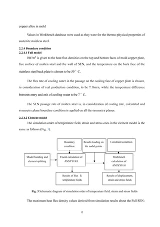
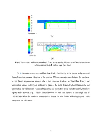
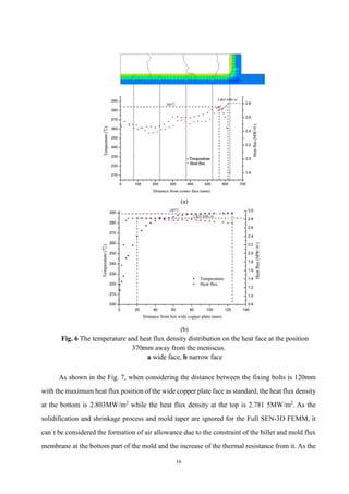
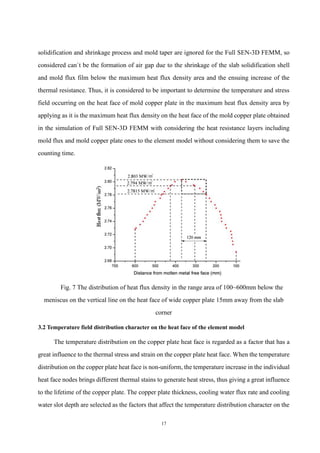
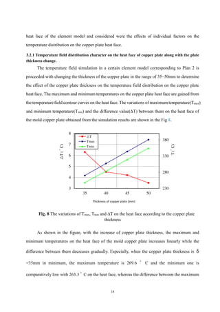
This document describes a simulation method for optimizing the cooling water slot structure in continuous casting molds. It involves using ANSYS software to simulate the temperature field in a 3D mold model combined with a submerged entry nozzle to determine the maximum heat flux density on the mold copper plate. This heat flux value is then applied to a copper plate element model to simulate thermal stresses and strains. Different water slot structure plans are analyzed to identify the most reasonable design based on temperatures, deformations and stresses. The goal is to confirm design factors that reduce thermal stresses on the mold copper plate during continuous casting.

![2
1. Introduction
Mold plays a very important role in the total cooling process of slab in the mold as the first
cooling stage where molten steel is solidified. Thus, the mold is called the “heart” of a continuous
caster [1, 2]. During the CC process, the molten steel is continuously poured into the water-cooled
mold through SEN, which forms a solidified shell of sufficient thickness when the slab is pulled
out. The slab quality, particularly regarding surface and internal cracks, is closely related to the
turbulent flow in the mold and the heat transfer through the heat face on the mold copper plate
during the solidification in a CC process [3]. A large temperature gradient is formed on the total
section of copper plate during CC process, which generates strain and thermal stress in the copper
plate. In case the thermal stress occurred by the temperature gradient in the mold copper plate is
excessive, strain occurs in the mold copper plate, and with increase of casting time and constant
iteration of heating and cooling process on the copper plate, micro cracks are generated and
extended to make an irretrievable accident in the copper plate [4].
Nowadays many studies on the temperature and thermal stress fields in the mold copper
plate have been progressed. Meng Xiangning and Zhu MiaoYong [5] established a 3-dimensional
finite element model to simulate temperature field of the heat face on the mold copper plate and
predicted the effect of casting speed on the temperature field distribution on the heat face of the
mold. Xin Xie and his co-workers [6] established 3-dimensional heat transfer model combined
with flow character of the cooling water to analyze the temperature field of the copper plate and
water slots by comparing with Dittus-Boelter and Selicher-Rouse models.
Wang Xudong [7], Ren Feifei [8] predicted the temperature field and heat flux density by
using numeric simulation method based on an inverse finite element (FE) model.
Badri Aand his co-workers [9] designed a mold simulator and progressed a basic experiment
on the heat transfer, the formation of solidified shell and oscillation mark during the CC process
of low-carbon steel, and demonstrated that the maximum heat flux density around the meniscus
changes in the range of 2.4~2.8MW/㎡ with the oscillating period of mold.
Fegming Dua et al [10] established 2-dimensional full finite-element model and analyzed
the 2-dimensional temperature field on the mold copper plate considered nickel coating layer in
the curved continuous caster. Zhao-zhen Cai et al [11, 12] simulated 2-dimensional numerical](https://image.slidesharecdn.com/asimulationmethodfortheoptimizationofcoolin-good-240306052627-6ef1f221/85/A_Simulation_Method_for_the_Optimization_of_Coolin-Good-pdf-3-320.jpg)
![3
value on the slab mold taper considered shrinkage of peritectic steel during the CC process and
predicted the distribution of the thickness of both mold flux and air gap along the height direction
of mold.
David T Stone and Brain G. Thomas [13] manufactured a simple experimental apparatus
and calculated numerically the temperature gradient, thermal conduction and thermal contact
resistance values on the section of the steel plate-mold flux gap-mold copper plate in the 2
dimensional model, using the temperature values measured from thermocouples that were placed
in different positions and the thermal conductivity of copper plate already known, heating the steel
plate from outside and injecting mold flux into the gap between the copper and steel plates.
Wand Xudong and his co-workers [14] developed mathematical inverse heat transfer
problem(IHTP) based on the temperature of mold and casting condition measured experimentally,
and simulated the effects of slag film evolution, the formation of air gap and the heat transfer
character to ascertain the non-equilibrium distribution of air gap and the liquid/solid slag film.
Éldarkhanov A. S. [15] demonstrated the effect of the oscillating motion and gap size
between CC mold and solidified crust, and the cooling water slot structure of mold copper plate
on the heat transfer into mold and derived the mathematical relational expression.
Meng Xiangning and Zhu Miaoyong [16] established a finite-element entity model of slab
continuous casting mold and studied the effects of thickness of copper plates and nickel layers and
depth of water slots on the temperature of heat face and cross section in the mold.
Liu Xudong , Zhu Miaoyong [4] established the 3-dimensional heat transfer and thermal
stress finite element model and predicted the temperature, deformation and thermal stress in a
continuous casting mold for steel slab by using a commercial finite element analysis package
ANSYSTM. Zhou J his co-workers [17] established the 3-dimensional coupled thermal–
mechanical model of a mold-billet system regarding the total top face of the slab in the mold as
the pouring hole during continuous casting, and analyzed the temperature field and stress field in
mold copper plate taking into account the latent heat released during phase transformation, the
heat transfer and the interaction between the moving billet and the mold.
Duan Mingnan and his co-workers [18] applied the heat flux density that calculated from
the inverse model using the temperature values measured by the thermocouples inserted in the](https://image.slidesharecdn.com/asimulationmethodfortheoptimizationofcoolin-good-240306052627-6ef1f221/85/A_Simulation_Method_for_the_Optimization_of_Coolin-Good-pdf-4-320.jpg)
![4
copper plate to the mold heat face and established 2-dimensional model that applied the heat
exchange coefficient derived from the Dittus-Boelter`s empirical formula on the cold surface of
copper plate. Next, they analyzed stress distribution on each section of mold copper plate by using
ANSYS program. W. Luo and his co-workers [19] established 2-dimensional thermal-elastic-
plastic-creep finite element models of beam blank molds with different water slot designs, the large
hole mold and the small hole mold, and studied their thermo-mechanical character by means of
ABAQUS software.
Based on these above reference data, we can draw some conclusions as follows:
In case of most of numerical simulations on temperature field in the mold copper plate,
empirical formulas on already-developed heat flux density were used or applied was the value
obtained by applying the temperature measured from the thermocouple inserted in the mold copper
plate to the inverse finite-element model, and applied the heat exchange coefficient between the
cold face on the copper plate and cooling water calculated by means of Dittus-Boelter`s formula
to the boundary condition of the cold face on the copper plate.
These methods have the advantages of saving time for simulation calculating, but in case
the temperature value measured from the thermocouple inserted in the mold isn`t precise enough,
it is felt difficult to ensure the accuracy of simulation result and especially to reflect the effect of
many factors as it was when using empirical formulas. To get the thing worse, there are hardly
thought to exist data where the temperature field in the mold copper plate is analyzed by using the
1/4 model of Full SEN-3D FEMM while considering heat flux into the mold copper plate from
molten steel in turbulent flow state, of course together with the thermal contact resistance such as
mold flux, gap and coating layer.
In this paper, simulated is the temperature field in a Full SEN-3D FEMM considered the
flux character of molten steel through SEN, mold flux and coating layer, and stainless back plate
in the mold, and also simulated is the temperature field and heat stress and strain on mold copper
and stainless back plates by applying the maximum heat flux density on the heat face of copper
plate in the model obtained from the above simulation to the element model of the mold copper
plate, thereby confirming the reasonable designing factors for the water slot structure on the mold
copper plate through this process.](https://image.slidesharecdn.com/asimulationmethodfortheoptimizationofcoolin-good-240306052627-6ef1f221/85/A_Simulation_Method_for_the_Optimization_of_Coolin-Good-pdf-5-320.jpg)
![8
① Mathematical model in fluid area
Continuity, momentum and standard k- equations used formulas in Ref [22] , and energy
equation that in Ref [11].
② Mathematical model in solid area
Energy equations in mold copper plate and stainless back plate area used formulas in Ref
[14].
③ Mathematical model on the adjacent wall between solid and fluid
Heat flux on the near-wall
Heat transfer between cooling water and mold copper plate is expressed as the following
expression
)
( w
c T
T
h
q
(1)
Here
h-coefficient of heat transfer around the wall
Tc-temperature of copper plate wall
Tw- temperature of water near the copper plate wall
Momentum equation
The standard wall functions in ANSYS Fluent are based on the work of Launder and
Spalding [20], and have been most widely used in industrial flows. The average velocity field in
the standard wall functions is expressed by non-dimensional velocity
*
U as follows.
*
*
ln
1
Ey
U
(2)
Here](https://image.slidesharecdn.com/asimulationmethodfortheoptimizationofcoolin-good-240306052627-6ef1f221/85/A_Simulation_Method_for_the_Optimization_of_Coolin-Good-pdf-9-320.jpg)
![9
- von Kármán constant (0.4187)
E-empirical coefficient(9.793)
y*-non-dimensional distance to the water slot wall surface
Energy equation
The coefficient of heat transfer in the flux boundary area during the heat transfer process
between copper plate and cooling water is calculated according to the local heat transfer condition.
It is presented as the following expressions, when considering the cooling water as incompressible
fluid. In ANSYS Fluent, the temperature wall functions include the contribution from the viscous
heating [21]. The law-of-the-wall implemented in ANSYS Fluent has the following composite
form.
*
*
*
*
*
*
2
1
4
1
*
ln
1
Pr
Pr
T
t
T
M
P
w
c
y
y
J
Ey
y
y
y
q
k
C
C
T
T
T
(3)
t
e
J
t
Pr
Pr
007
.
0
4
3
28
.
0
1
1
Pr
Pr
24
.
9
(4)
In these expressions J is calculated by using the formula suggested by Jayatilleke [21].
Here
q
-heat flux on the wall
Pr- molecular Prandtl number ( k
CP
Pr )
t
Pr
- turbulent Prandtl number (0.85 at the wall)
-density, kg/m3
p
C
-specific heat,
K
kg
J
Cμ-constant](https://image.slidesharecdn.com/asimulationmethodfortheoptimizationofcoolin-good-240306052627-6ef1f221/85/A_Simulation_Method_for_the_Optimization_of_Coolin-Good-pdf-10-320.jpg)
![11
Sij- deviatoric stress tensor
σy- yield stress
E and E1-Young`s modulus and linear hardening gradient
εe- Von-Mises equivalent strain
Thermal strain by the temperature change ΔT is as follows.
ij
T
ij T
(8)
Here
α-the coefficient of thermal expansion
δij-Kronecker’s delta
2.2.3 Process factors and thermo-physical properties of the materials
The CC process factors used in the simulation are listed in Table 3.
Table 3 The CC process factors used in the simulation
Item Value
Casting speed, m/min 0.8
Slab width, mm 1 250
Slab thickness, mm 250
Mold height, mm 1 200
Meniscus level(below mold top face), mm 100
Temperature difference between entry and exit of cooling
water(wide face/narrow face) , ゚ C
7.2/7.4
Water flux(wide face/narrow face) , l/min 6 537/962.9
Physical properties of carbon steel described in Ref [23] are used in the simulation.
The thermo-physical properties of Ni-Cr layer and mold flux one on solid phase are listed
in Table 4.
Table 4 Thermo-physical properties of Ni-Cr and mold flux layers
Ni-Cr coating layer Value solid slag layer Value
Density, kg/m3
7 950 Density, kg/m3
2 500
Specific heat, J/(kg·゚ C) 615 Specific heat, J/(kg·゚ C) 685
Heat conductivity W/(m·゚ C) 20 Heat conductivity W/(m·゚ C) 1.3
Data reported in Ref [19] were used for the thermo-physical properties of Cu-0.65Cr-0.1Zr](https://image.slidesharecdn.com/asimulationmethodfortheoptimizationofcoolin-good-240306052627-6ef1f221/85/A_Simulation_Method_for_the_Optimization_of_Coolin-Good-pdf-12-320.jpg)
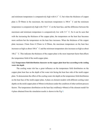
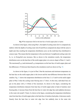
![21
area(0~17mm).
Fig. 10 The variations of Tmax, Tmin and ΔT on the heat face according to plan number
In the given process parameter condition, the ABCD area in the figure is the inner area of
the water slot where the temperature is higher than 100 ゚ C, which is located on the heat face side
and the maximum temperature in this area is 137.5 ゚ C. Under the given process factor condition,
as the ABCD area in the figure is the internal one of the water slots with the temperature above
100 ゚ C, the maximum temperature in this area reaches 137.5 ゚ C. As the boiling point of water is
168.501 ゚ C when the cooling water pressure is 0.7MPa derived from the pressure-boiling point
relational formula(1) in Ref [6], thus it can be seen that the boiling phenomenon doesn`t present
in the ABCD areas.
306.1 306.8 309.2 310.2
303 302.3 298.5 300.9
3.1 4.5 10.7 9.1
0
60
120
180
240
300
360
plan 1 plan 2 plan 3 plan 4
T
(
゚
C)
Tmax
Tmin
△T
Plan number](https://image.slidesharecdn.com/asimulationmethodfortheoptimizationofcoolin-good-240306052627-6ef1f221/85/A_Simulation_Method_for_the_Optimization_of_Coolin-Good-pdf-22-320.jpg)
![22
Fig. 11 The temperature distribution on the lines 3~6.
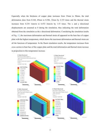
3.3 Deformation and stress distribution in the element model
The mold copper plate has the effect of elastic and plastic strain due to the temperature
gradient on the section during working process; so once plastically strained, it remains as the
permanent deformation state after working to strain-harden the mold copper alloy. If such
permanent deformation accumulates, the heat face shape deforms to affect the solidification shell
type of slab and furthermore, tends to cause an accident of slab or copper plate crack. Generally,
thermal strain mainly depends on temperature gradient and the thermal expansion coefficient in
the mold copper alloy [4]. Strain and stress field simulation on the element model is proceeded
according to the strain and stress field simulation orders shown in Fig. 3. Applying Fluent &
Workbench programs of ANSYS 18.0 Package to the same geometrical objects, the temperature
values on each node in solid determined from Fluent simulation are loaded as initial ones thermal
and structural analysis model to proceed the analysis. Fig. 12 shows the simulation result in the
element model in Plan 2.
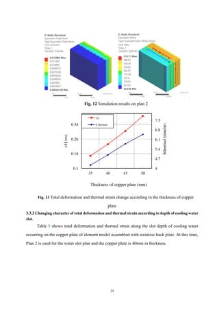
3.3.1 Changing character of total deformation and thermal strain according to thickness of copper
plate
Fig. 13 shows total deformation and thermal strain occurring on the copper plate of element
model assembled with stainless back plate. At this time, Plan 2 is chosen as the water slot plan and
the cooling water flux rate is 7.16m/s. As shown in the figure, the more the copper plate increases,
the more nearly linearly the total deformation and thermal strain on the copper plate increases.](https://image.slidesharecdn.com/asimulationmethodfortheoptimizationofcoolin-good-240306052627-6ef1f221/85/A_Simulation_Method_for_the_Optimization_of_Coolin-Good-pdf-23-320.jpg)
![28
Funding
This research work was not funded.
Availability of data and materials
The authors confirm that the data supporting the findings of this study are available within this
article.
Availability of code
The code that support the findings of this study are available from the corresponding author [Sang
Chol Om], upon a reasonable request.
References
1. Wang TM, Cai SW, Xu J, Du YY, Zhu J, Xu JJ, Li TJ(2010) Continuous casting mould for
square steel billet optimised by solidification shrinkage simulation. Ironmaking and
Steelmaking 37(5):341 346
2. Pandey JC, Raj Manish, Mishra Rajesh, Tripathy VK, Bandyopadhyay N(2008) Failure of
Nickel Coating on a Copper Mold of a Slab Caster. J Fail. Anal. and Preven. 8: 3–11
3. Long Mujun, Chen Huabiao, Chen Dengfu, Yu Sheng, Liang Bin, Duan Huamei(2018) A
Combined Hybrid 3-D/2-D Model for Flow and Solidification Prediction during Slab
Continuous Casting. Metals 8: 182–191
4. Liu Xudong, Zhu Miaoyong(2006) Finite Element Analysis of Thermal and Mechanical
Character in a Slab Continuous Casting Mold. ISIJ International 46(11): 1652–1659
5. Meng Xiangning, Zhu Miaoyong(2009) Thermal Character of Hot Copper Plates for Slab
Continuous Casting Mold with High Casting Speed. ISIJ International 49(9): 1356–1361
6. Xin Xie, Chen Dengfu, Long Haijun, Long Mujun, Kui Lv (2014) Mathematical Modeling of
Heat Transfer in Mold Copper Coupled with Cooling Water During the Slab Continuous
Casting Process. METALLURGICALAND MATERIALS TRANSACTIONS 45(12): 2442–
2452
7. Wang Xudong, Tang Ling, Zang Xinyang, Yao Man(2012) Mold transient heat transfer character
based on measurement and inverse analysis of slab continuous casting. Journal of Materials
Processing Technology 212: 1811–1818
8 Ren Feifei,Zhang Hui,Wang Weining,Wang Minglin(2015) Numerical simulation of actual](https://image.slidesharecdn.com/asimulationmethodfortheoptimizationofcoolin-good-240306052627-6ef1f221/85/A_Simulation_Method_for_the_Optimization_of_Coolin-Good-pdf-29-320.jpg)