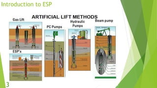
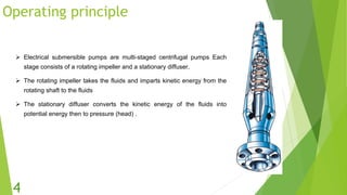
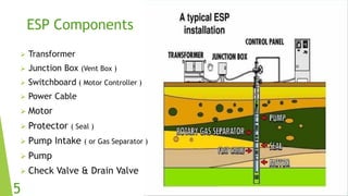
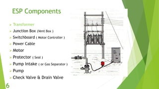
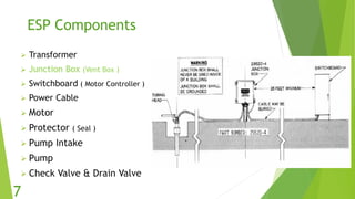
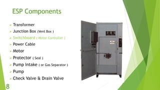
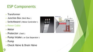
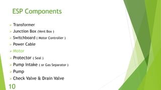
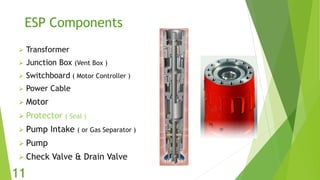
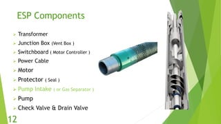
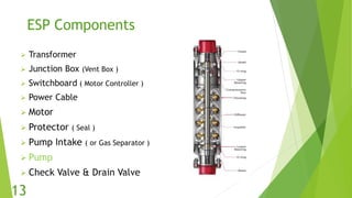
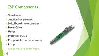
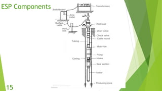
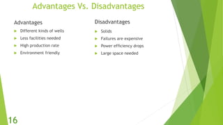
Electric Submersible Pumps
(ESP)
Presented by :
Mohamed Adel Helal
Muhammed Alaa Afifi
Waheed Shams
Moustafa Magdy
1
Table of Contents
 Introduction to ESP
 Operating principle
 ESP components
 Advantages & Disadvantages of ESP
 Application of ESP pump by using PIPESIM.
2
Introduction to ESP
3
Operating principle
 Electrical submersible pumps are multi-staged centrifugal pumps Each
stage consists of a rotating impeller and a stationary diffuser.
 The rotating impeller takes the fluids and imparts kinetic energy from the
rotating shaft to the fluids
 The stationary diffuser converts the kinetic energy of the fluids into
potential energy then to pressure (head) .
4
ESP Components
 Transformer
 Junction Box (Vent Box )
 Switchboard ( Motor Controller )
 Power Cable
 Motor
 Protector ( Seal )
 Pump Intake ( or Gas Separator )
 Pump
 Check Valve & Drain Valve
5
ESP Components
 Transformer
 Junction Box (Vent Box )
 Switchboard ( Motor Controller )
 Power Cable
 Motor
 Protector ( Seal )
 Pump Intake ( or Gas Separator )
 Pump
 Check Valve & Drain Valve
6
ESP Components
 Transformer
 Junction Box (Vent Box )
 Switchboard ( Motor Controller )
 Power Cable
 Motor
 Protector ( Seal )
 Pump Intake
 Pump
 Check Valve & Drain Valve
7
ESP Components
 Transformer
 Junction Box (Vent Box )
 Switchboard ( Motor Controller )
 Power Cable
 Motor
 Protector ( Seal )
 Pump Intake ( or Gas Separator )
 Pump
 Check Valve & Drain Valve
8
ESP Components
 Transformer
 Junction Box (Vent Box )
 Switchboard ( Motor Controller )
 Power Cable
 Motor
 Protector ( Seal )
 Pump Intake ( or Gas Separator )
 Pump
 Check Valve & Drain Valve
9
ESP Components
 Transformer
 Junction Box (Vent Box )
 Switchboard ( Motor Controller )
 Power Cable
 Motor
 Protector ( Seal )
 Pump Intake ( or Gas Separator )
 Pump
 Check Valve & Drain Valve
10
ESP Components
 Transformer
 Junction Box (Vent Box )
 Switchboard ( Motor Controller )
 Power Cable
 Motor
 Protector ( Seal )
 Pump Intake ( or Gas Separator )
 Pump
 Check Valve & Drain Valve
11
ESP Components
 Transformer
 Junction Box (Vent Box )
 Switchboard ( Motor Controller )
 Power Cable
 Motor
 Protector ( Seal )
 Pump Intake ( or Gas Separator )
 Pump
 Check Valve & Drain Valve
12
ESP Components
 Transformer
 Junction Box (Vent Box )
 Switchboard ( Motor Controller )
 Power Cable
 Motor
 Protector ( Seal )
 Pump Intake ( or Gas Separator )
 Pump
 Check Valve & Drain Valve
13
ESP Components
 Transformer
 Junction Box (Vent Box )
 Switchboard ( Motor Controller )
 Power Cable
 Motor
 Protector ( Seal )
 Pump Intake ( or Gas Separator )
 Pump
 Check Valve & Drain Valve
14
ESP Components
15
Advantages Vs. Disadvantages
Advantages
 Different kinds of wells
 Less facilities needed
 High production rate
 Environment friendly
Disadvantages
 Solids
 Failures are expensive
 Power efficiency drops
 Large space needed
16
Table of Contents
 Introduction to ESP
 Operating principle
 ESP components
 Advantages & Disadvantages of ESP
 One of the Application of PIPESIM is ESP pump design and installation.
17
One of the Application of PIPESIM is ESP
pump design and installation.
In this case study we will discuss:-
A. Production rate from a vertical well.
B. Production rate with the same vertical well after installation of ESP
pump.
C. Discuss the effect of ESP Pump installation in the vertical well
18
A-Production rate from a vertical well:-
1. Steps of vertical well design.
2. Calculate the well Production rate.
3. Sensitivity input of reservoir pressure.
4. Effect of Increasing water cut.
19
1-Steps of vertical well design.
20
Input data for the design:-
well – tubing – fluid stream.
21
A-Production rate from a vertical well:-
1. Steps of vertical well design.
2. Calculate the well Production rate.
3. sensitivity of reservoir pressure.
4. Effect of Increasing water cut
22
2-Calculate the well Production rate.
Operations – Nodal analysis:- Entering the outlet pressure.
23
Run the model :- stable point.
24
A-Production rate from a vertical well:-
1. Steps of vertical well design.
2. Calculate the well Production rate.
3. sensitivity input data of reservoir pressure.
4. Effect of Increasing water cut
25
3- sensitivity of reservoir pressure.
Input:-
26
Run the model.
27
A-Production rate from a vertical well:-
1. Steps of vertical well design.
2. Calculate the well Production rate.
3. sensitivity of reservoir pressure.
4. Effect of Increasing water cut
28
4-Effect of Increasing water cut
29
29
Application of ESP pump by using PIPESIM
In this case study we will discuss:-
A. Production rate from a vertical well.
B. Production rate with the same vertical well after installation of ESP
pump.
C. Discuss the effect of ESP Pump.
30
B. Production rate with the same vertical well
after installation of ESP pump.
1-Steps of ESP pump installation :-
 ESP design
 Pump selection
 ESP calculation
 Motor selection
2- calculation a production rate.
31
1-Steps of ESP pump installation :-
Artificial lift then ESP design
32
Pump selection:-
33
Pump calculations:-
34
Motor Selection:-
35
Calculating Production rate :-
Q=10000 STB/d Pwf=2400 psi
36
Application of ESP pump by using PIPESIM
In this case study we will discuss:-
A. Production rate from a vertical well.
B. Production rate with the same vertical well after installation of ESP
pump.
C. Discuss the effect of ESP Pump.
37
c. Discuss the effect of ESP Pump.
In the first case :- from graph
Stable point Pwf =2670 PSIA , Q= 7800 STB/D
In the second case :- from graph
stable point Pwf=2400 PSIA Q= 10000 STB/D
ESP Pump JD is to make a pressure aid.
38
Conclusion:-
o Operating principle of ESP
o ESP components
o Advantages & Disadvantages of ESP
o One of the Application of PIPESIM is ESP pump design and installation.
39
Thank you .
40

Esp installation

  • 1.
    Electric Submersible Pumps (ESP) Presentedby : Mohamed Adel Helal Muhammed Alaa Afifi Waheed Shams Moustafa Magdy 1
  • 2.
    Table of Contents Introduction to ESP  Operating principle  ESP components  Advantages & Disadvantages of ESP  Application of ESP pump by using PIPESIM. 2
  • 3.
  • 4.
    Operating principle  Electricalsubmersible pumps are multi-staged centrifugal pumps Each stage consists of a rotating impeller and a stationary diffuser.  The rotating impeller takes the fluids and imparts kinetic energy from the rotating shaft to the fluids  The stationary diffuser converts the kinetic energy of the fluids into potential energy then to pressure (head) . 4
  • 5.
    ESP Components  Transformer Junction Box (Vent Box )  Switchboard ( Motor Controller )  Power Cable  Motor  Protector ( Seal )  Pump Intake ( or Gas Separator )  Pump  Check Valve & Drain Valve 5
  • 6.
    ESP Components  Transformer Junction Box (Vent Box )  Switchboard ( Motor Controller )  Power Cable  Motor  Protector ( Seal )  Pump Intake ( or Gas Separator )  Pump  Check Valve & Drain Valve 6
  • 7.
    ESP Components  Transformer Junction Box (Vent Box )  Switchboard ( Motor Controller )  Power Cable  Motor  Protector ( Seal )  Pump Intake  Pump  Check Valve & Drain Valve 7
  • 8.
    ESP Components  Transformer Junction Box (Vent Box )  Switchboard ( Motor Controller )  Power Cable  Motor  Protector ( Seal )  Pump Intake ( or Gas Separator )  Pump  Check Valve & Drain Valve 8
  • 9.
    ESP Components  Transformer Junction Box (Vent Box )  Switchboard ( Motor Controller )  Power Cable  Motor  Protector ( Seal )  Pump Intake ( or Gas Separator )  Pump  Check Valve & Drain Valve 9
  • 10.
    ESP Components  Transformer Junction Box (Vent Box )  Switchboard ( Motor Controller )  Power Cable  Motor  Protector ( Seal )  Pump Intake ( or Gas Separator )  Pump  Check Valve & Drain Valve 10
  • 11.
    ESP Components  Transformer Junction Box (Vent Box )  Switchboard ( Motor Controller )  Power Cable  Motor  Protector ( Seal )  Pump Intake ( or Gas Separator )  Pump  Check Valve & Drain Valve 11
  • 12.
    ESP Components  Transformer Junction Box (Vent Box )  Switchboard ( Motor Controller )  Power Cable  Motor  Protector ( Seal )  Pump Intake ( or Gas Separator )  Pump  Check Valve & Drain Valve 12
  • 13.
    ESP Components  Transformer Junction Box (Vent Box )  Switchboard ( Motor Controller )  Power Cable  Motor  Protector ( Seal )  Pump Intake ( or Gas Separator )  Pump  Check Valve & Drain Valve 13
  • 14.
    ESP Components  Transformer Junction Box (Vent Box )  Switchboard ( Motor Controller )  Power Cable  Motor  Protector ( Seal )  Pump Intake ( or Gas Separator )  Pump  Check Valve & Drain Valve 14
  • 15.
  • 16.
    Advantages Vs. Disadvantages Advantages Different kinds of wells  Less facilities needed  High production rate  Environment friendly Disadvantages  Solids  Failures are expensive  Power efficiency drops  Large space needed 16
  • 17.
    Table of Contents Introduction to ESP  Operating principle  ESP components  Advantages & Disadvantages of ESP  One of the Application of PIPESIM is ESP pump design and installation. 17
  • 18.
    One of theApplication of PIPESIM is ESP pump design and installation. In this case study we will discuss:- A. Production rate from a vertical well. B. Production rate with the same vertical well after installation of ESP pump. C. Discuss the effect of ESP Pump installation in the vertical well 18
  • 19.
    A-Production rate froma vertical well:- 1. Steps of vertical well design. 2. Calculate the well Production rate. 3. Sensitivity input of reservoir pressure. 4. Effect of Increasing water cut. 19
  • 20.
    1-Steps of verticalwell design. 20
  • 21.
    Input data forthe design:- well – tubing – fluid stream. 21
  • 22.
    A-Production rate froma vertical well:- 1. Steps of vertical well design. 2. Calculate the well Production rate. 3. sensitivity of reservoir pressure. 4. Effect of Increasing water cut 22
  • 23.
    2-Calculate the wellProduction rate. Operations – Nodal analysis:- Entering the outlet pressure. 23
  • 24.
    Run the model:- stable point. 24
  • 25.
    A-Production rate froma vertical well:- 1. Steps of vertical well design. 2. Calculate the well Production rate. 3. sensitivity input data of reservoir pressure. 4. Effect of Increasing water cut 25
  • 26.
    3- sensitivity ofreservoir pressure. Input:- 26
  • 27.
  • 28.
    A-Production rate froma vertical well:- 1. Steps of vertical well design. 2. Calculate the well Production rate. 3. sensitivity of reservoir pressure. 4. Effect of Increasing water cut 28
  • 29.
    4-Effect of Increasingwater cut 29 29
  • 30.
    Application of ESPpump by using PIPESIM In this case study we will discuss:- A. Production rate from a vertical well. B. Production rate with the same vertical well after installation of ESP pump. C. Discuss the effect of ESP Pump. 30
  • 31.
    B. Production ratewith the same vertical well after installation of ESP pump. 1-Steps of ESP pump installation :-  ESP design  Pump selection  ESP calculation  Motor selection 2- calculation a production rate. 31
  • 32.
    1-Steps of ESPpump installation :- Artificial lift then ESP design 32
  • 33.
  • 34.
  • 35.
  • 36.
    Calculating Production rate:- Q=10000 STB/d Pwf=2400 psi 36
  • 37.
    Application of ESPpump by using PIPESIM In this case study we will discuss:- A. Production rate from a vertical well. B. Production rate with the same vertical well after installation of ESP pump. C. Discuss the effect of ESP Pump. 37
  • 38.
    c. Discuss theeffect of ESP Pump. In the first case :- from graph Stable point Pwf =2670 PSIA , Q= 7800 STB/D In the second case :- from graph stable point Pwf=2400 PSIA Q= 10000 STB/D ESP Pump JD is to make a pressure aid. 38
  • 39.
    Conclusion:- o Operating principleof ESP o ESP components o Advantages & Disadvantages of ESP o One of the Application of PIPESIM is ESP pump design and installation. 39
  • 40.