Download as PDF, PPTX
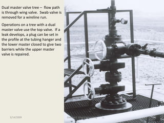
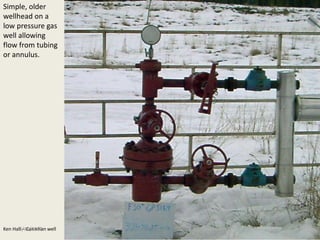
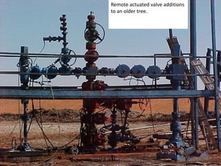
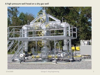
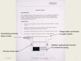
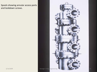
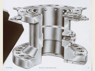
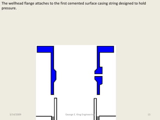
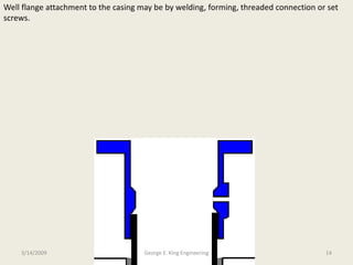
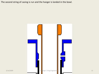
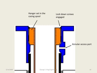
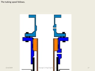
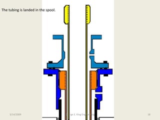
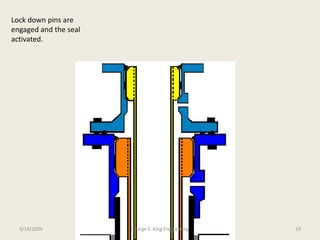
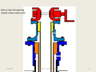
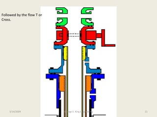
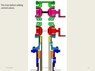
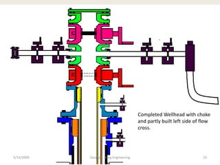
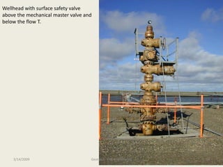
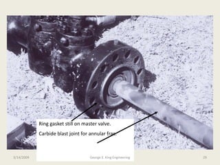
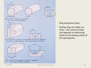
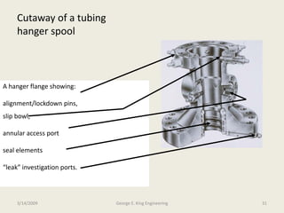
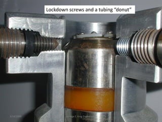

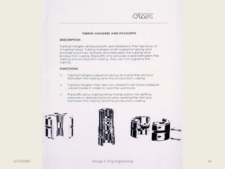
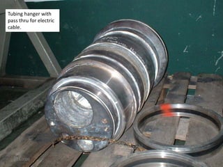
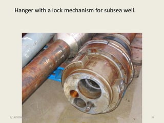
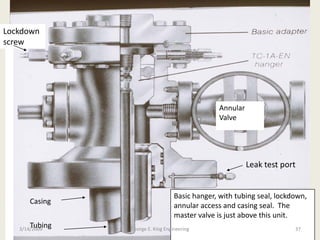
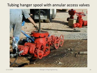
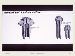
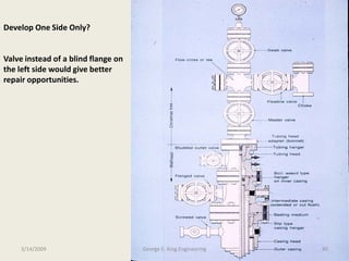
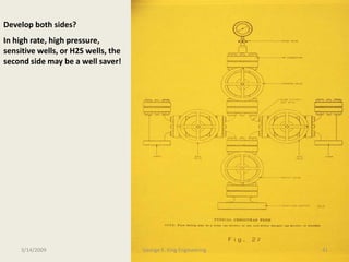
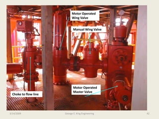
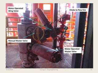
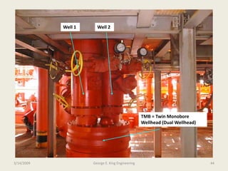
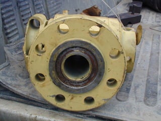
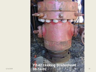

The document discusses wellheads and their components. It describes how wellheads are made up of multiple pieces including the casing head, casing hangers, spools, tubing hangers, master valves, and flow trees. It provides pictures and descriptions of these individual components and how they assemble to form the full wellhead. It also discusses design considerations, installation procedures, sealing methods, and testing of wellhead equipment.


