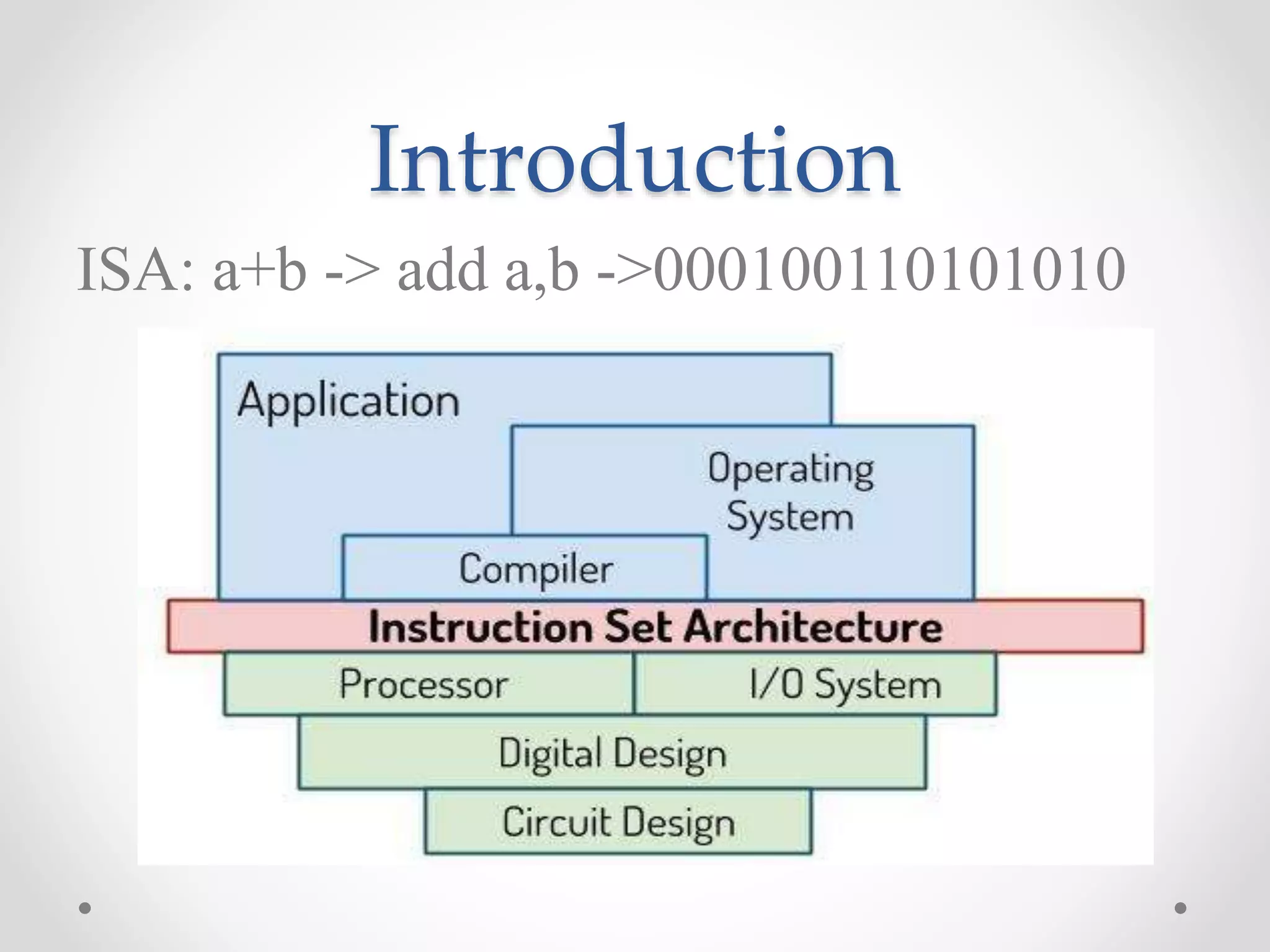
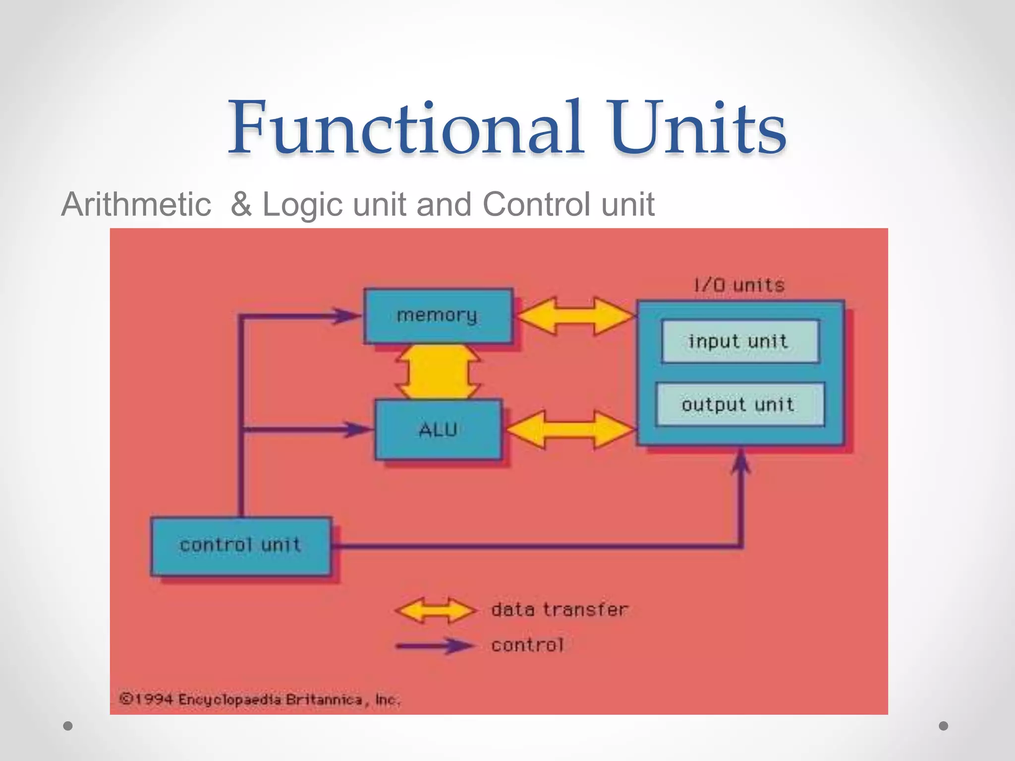
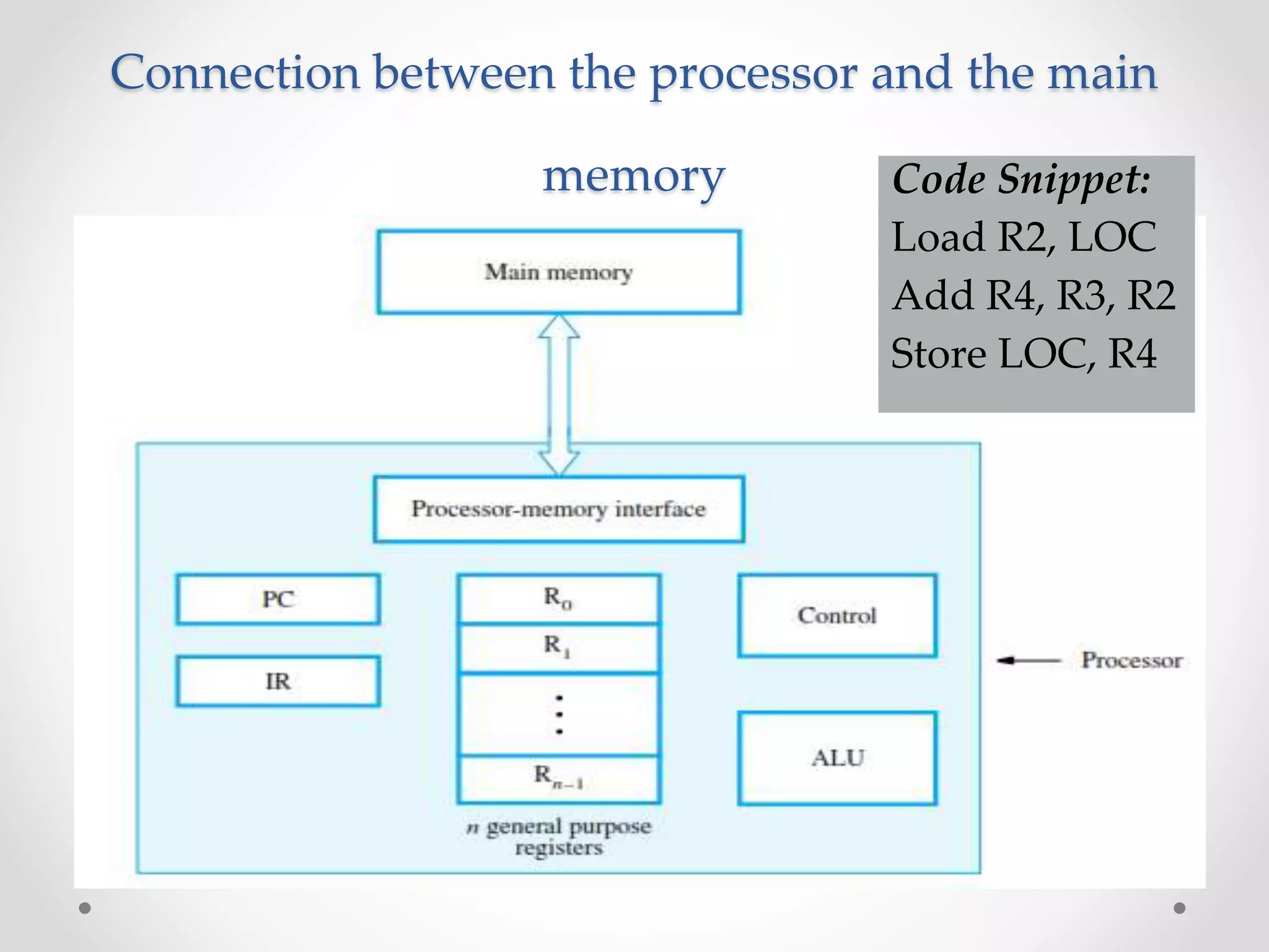
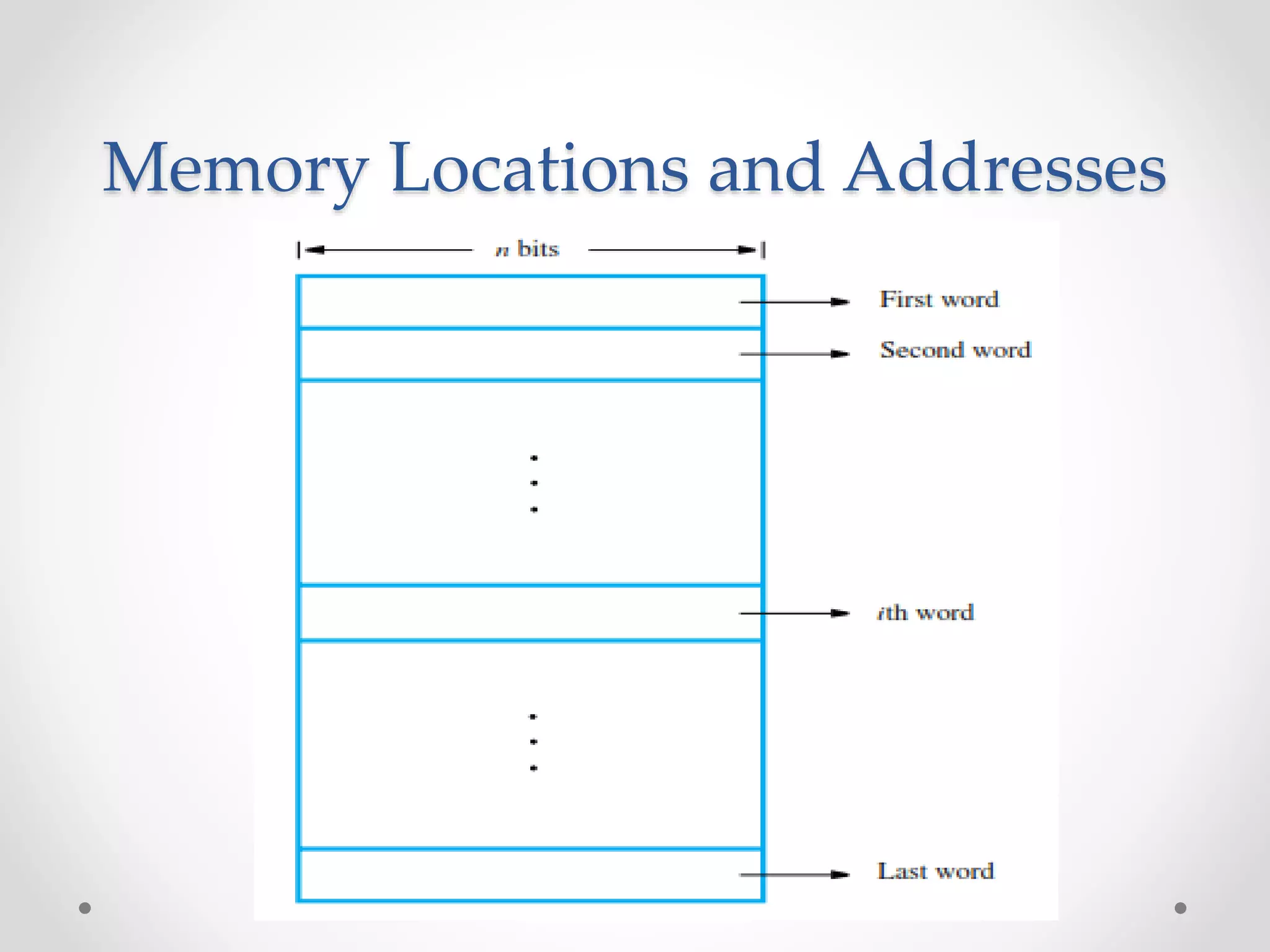
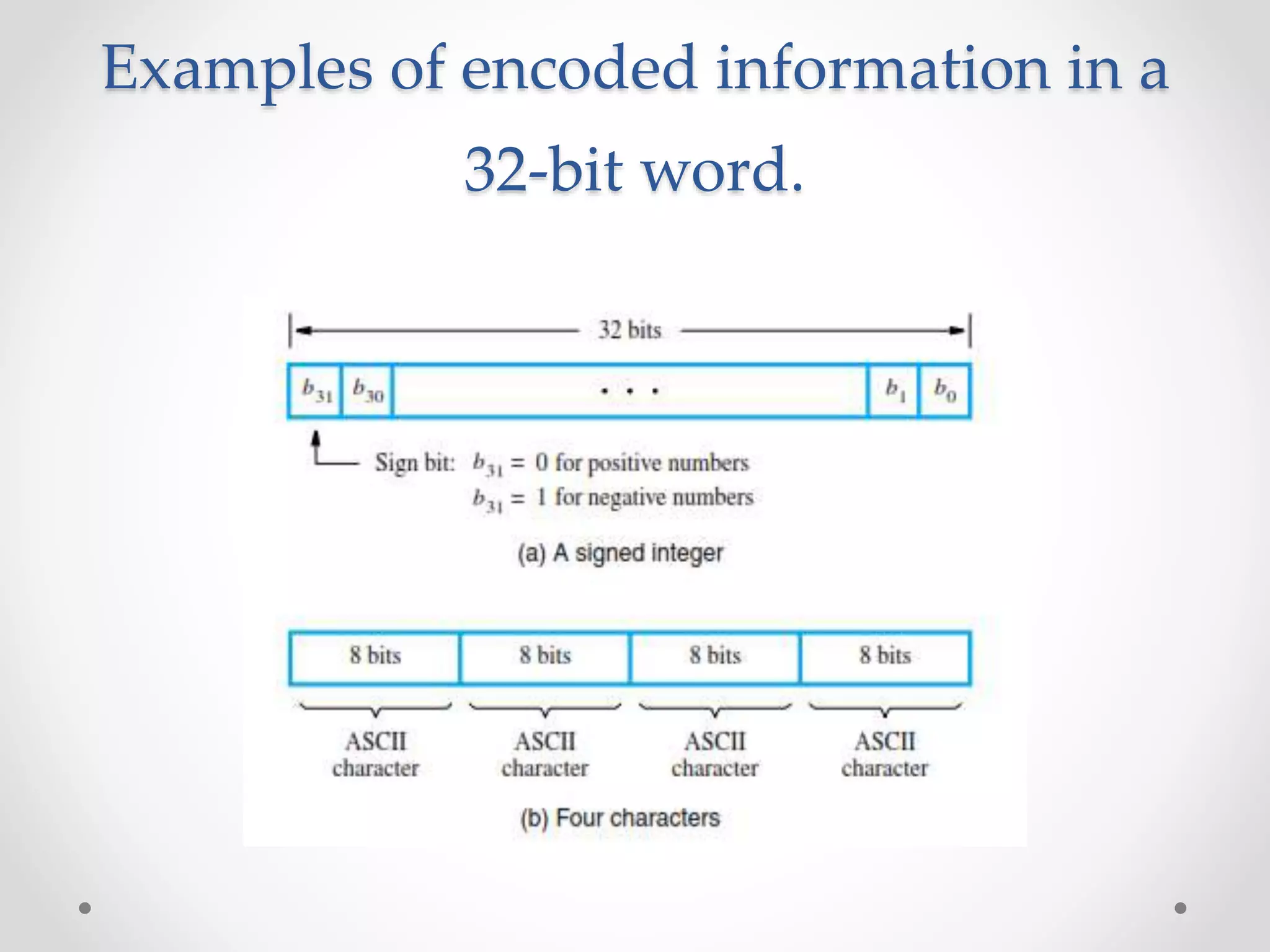
The document outlines a course on computer architecture at Velammal Engineering College, focusing on fundamental topics such as computer structure, arithmetic logic units, pipelined execution, parallel processing, and memory systems. It includes detailed syllabi for various units, textbook references, and explanations of instruction set architecture, particularly MIPS. The course aims to equip students with knowledge to analyze and design computer components and understand system performance and operations.
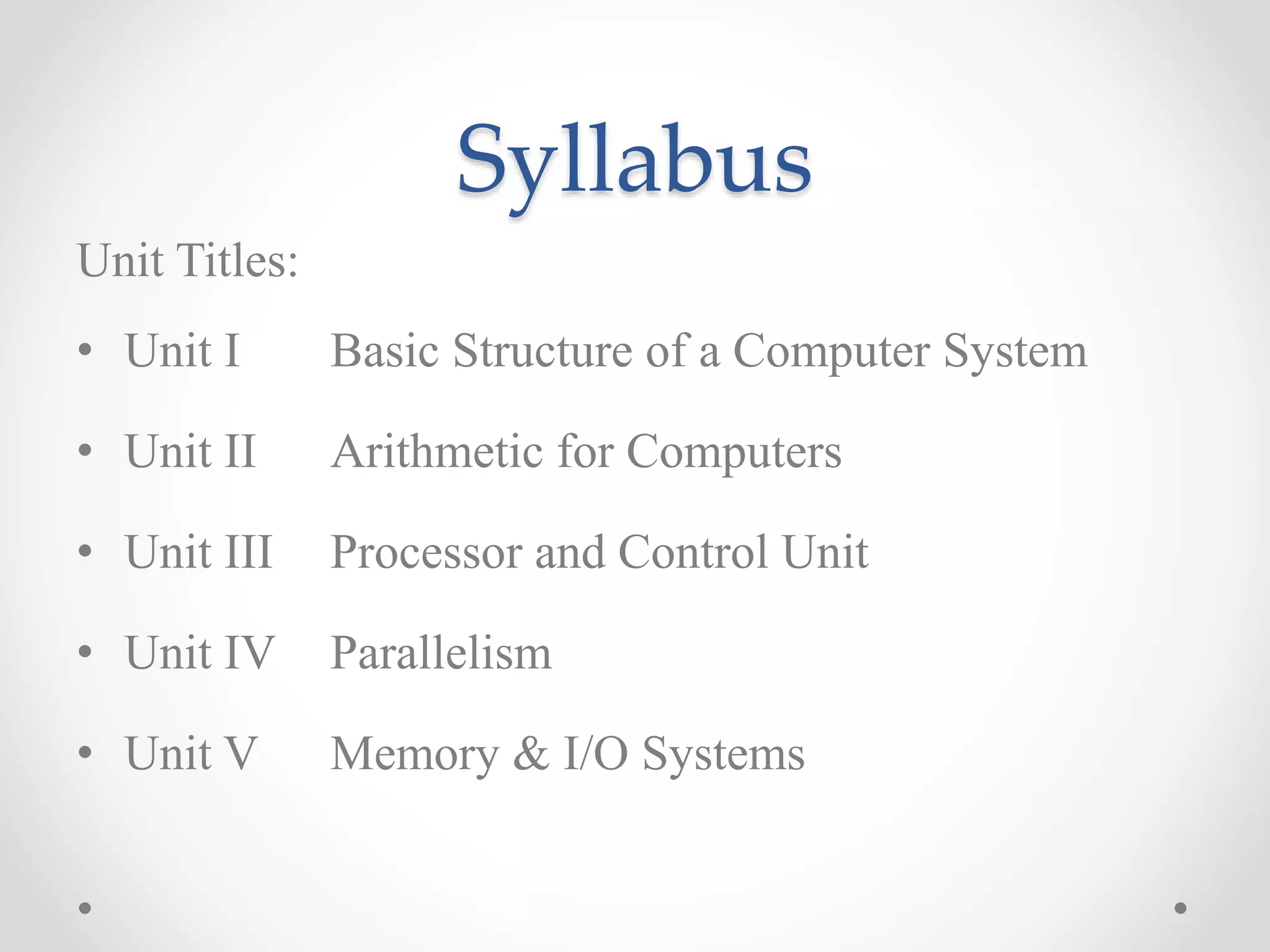


![Load/Store Instructions
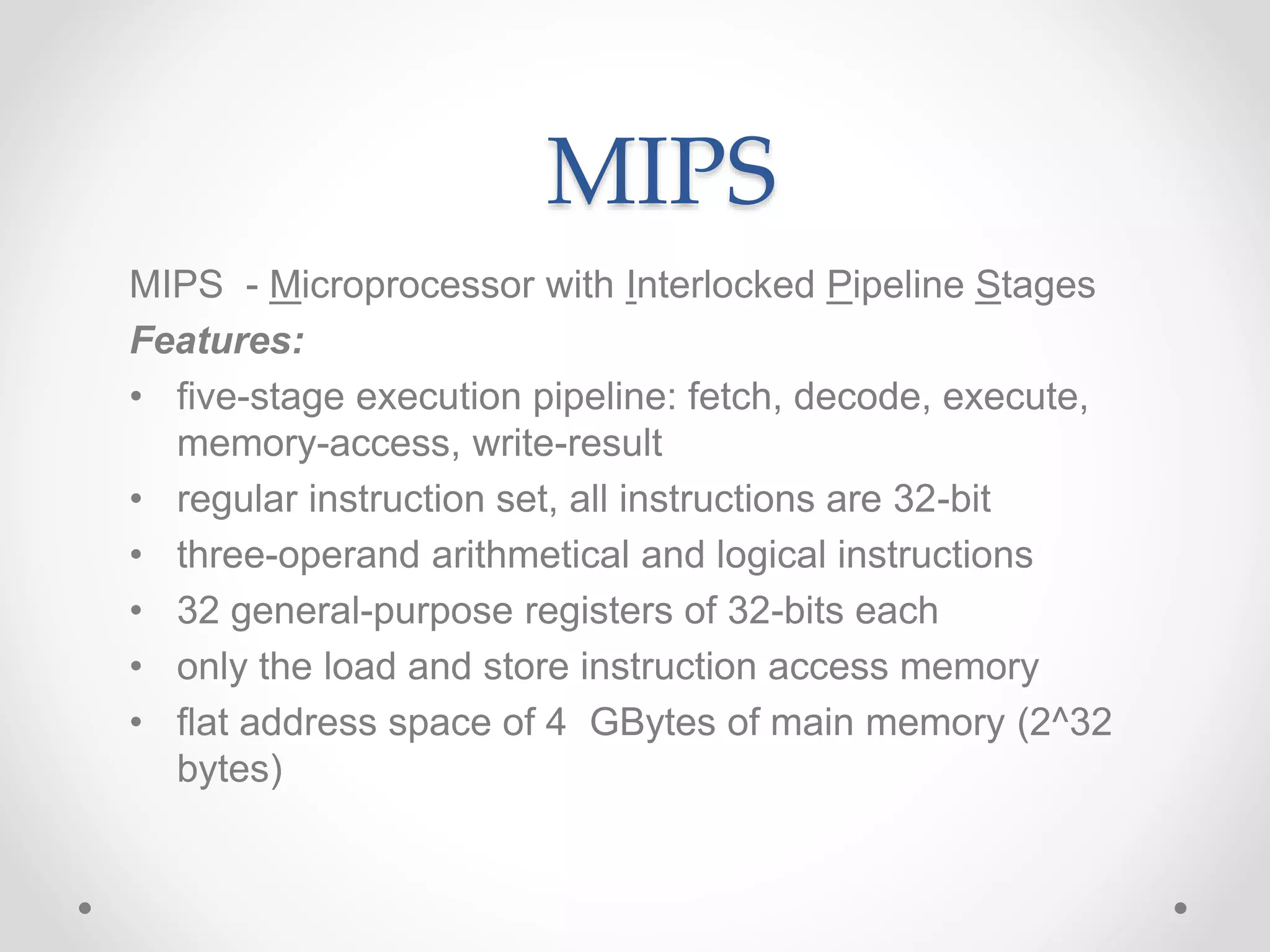
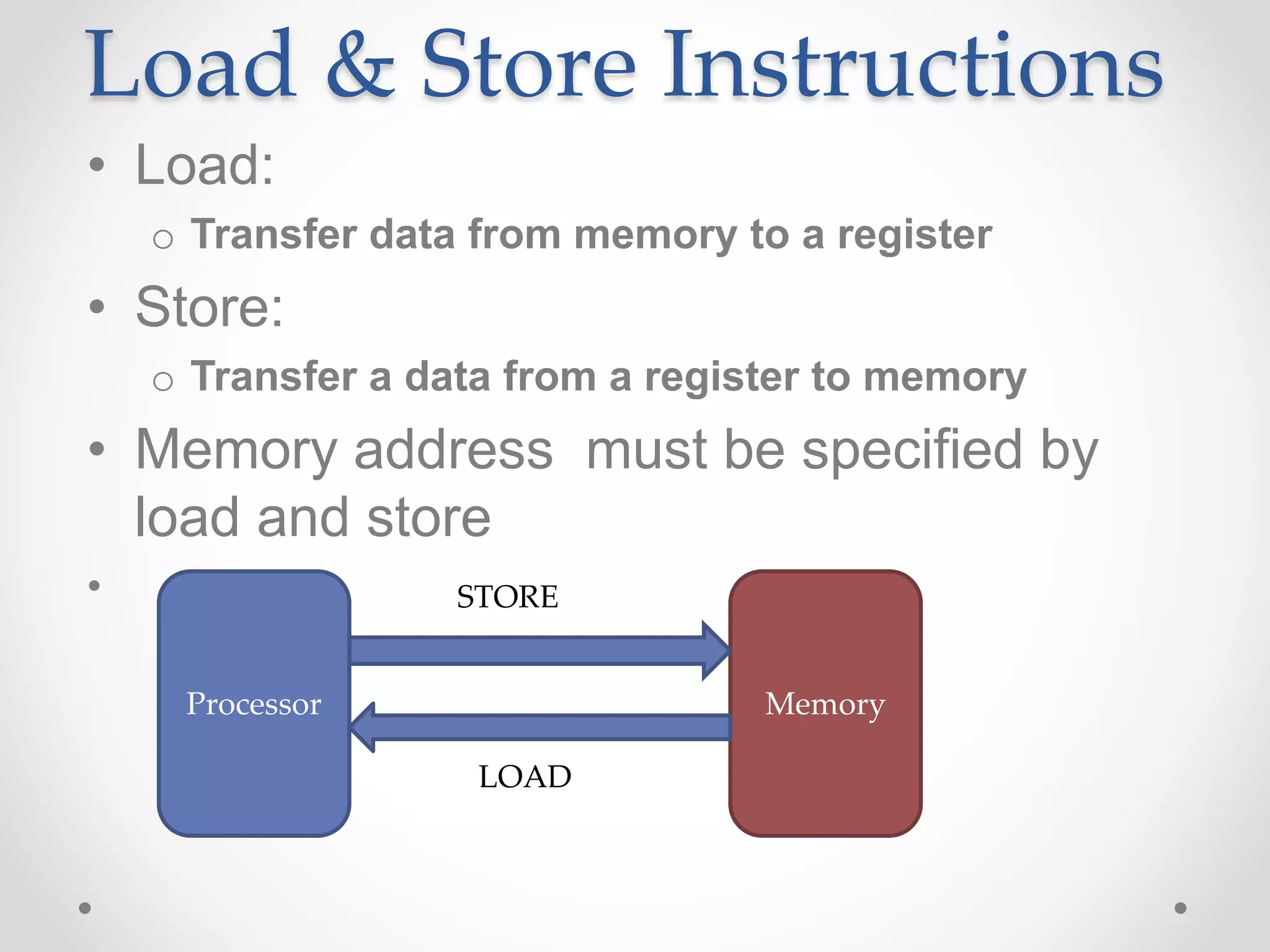
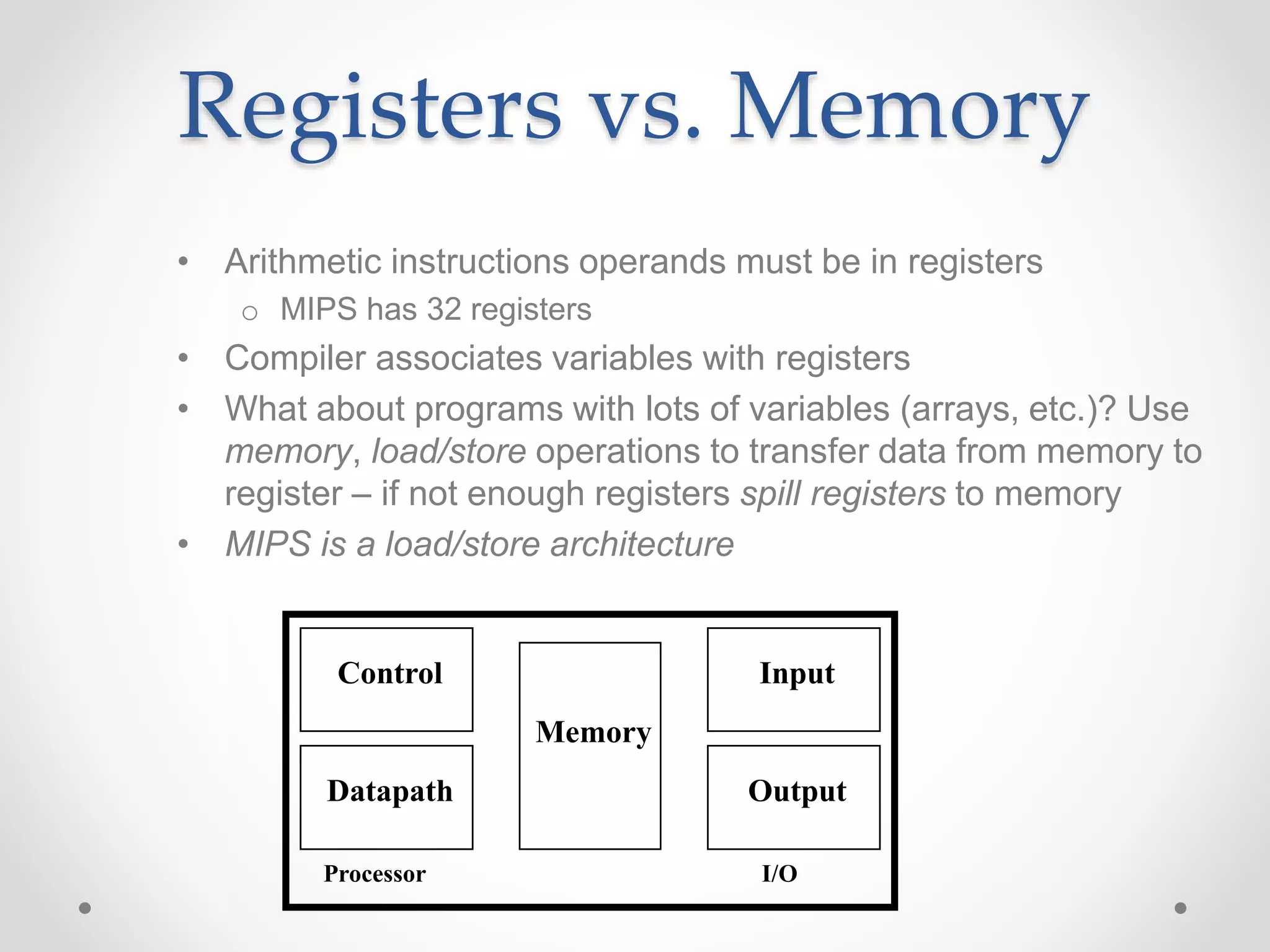
• Load and store instructions
• Example:
C code: A[8] = h + A[8];
MIPS code (load): lw $t0, 32($s3)
(arithmetic): add $t0, $s2, $t0
(store): sw $t0, 32($s3)
• Load word has destination first, store has destination last
• Remember MIPS arithmetic operands are registers, not memory
locations
o therefore, words must first be moved from memory to registers using
loads before they can be operated on; then result can be stored back to
memory
offset address
value](https://image.slidesharecdn.com/unitica-220307130513/75/Basic-Structure-of-a-Computer-System-56-2048.jpg)
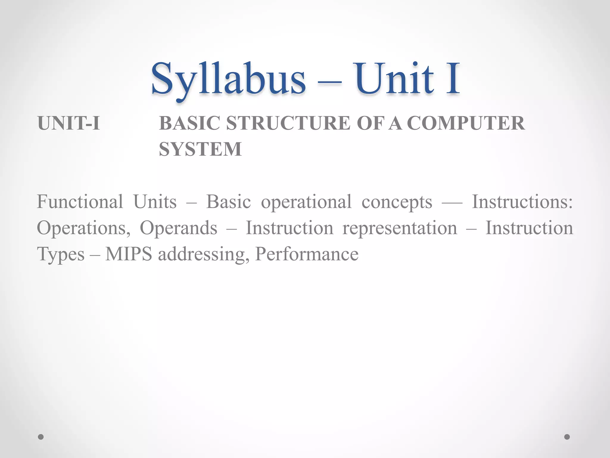
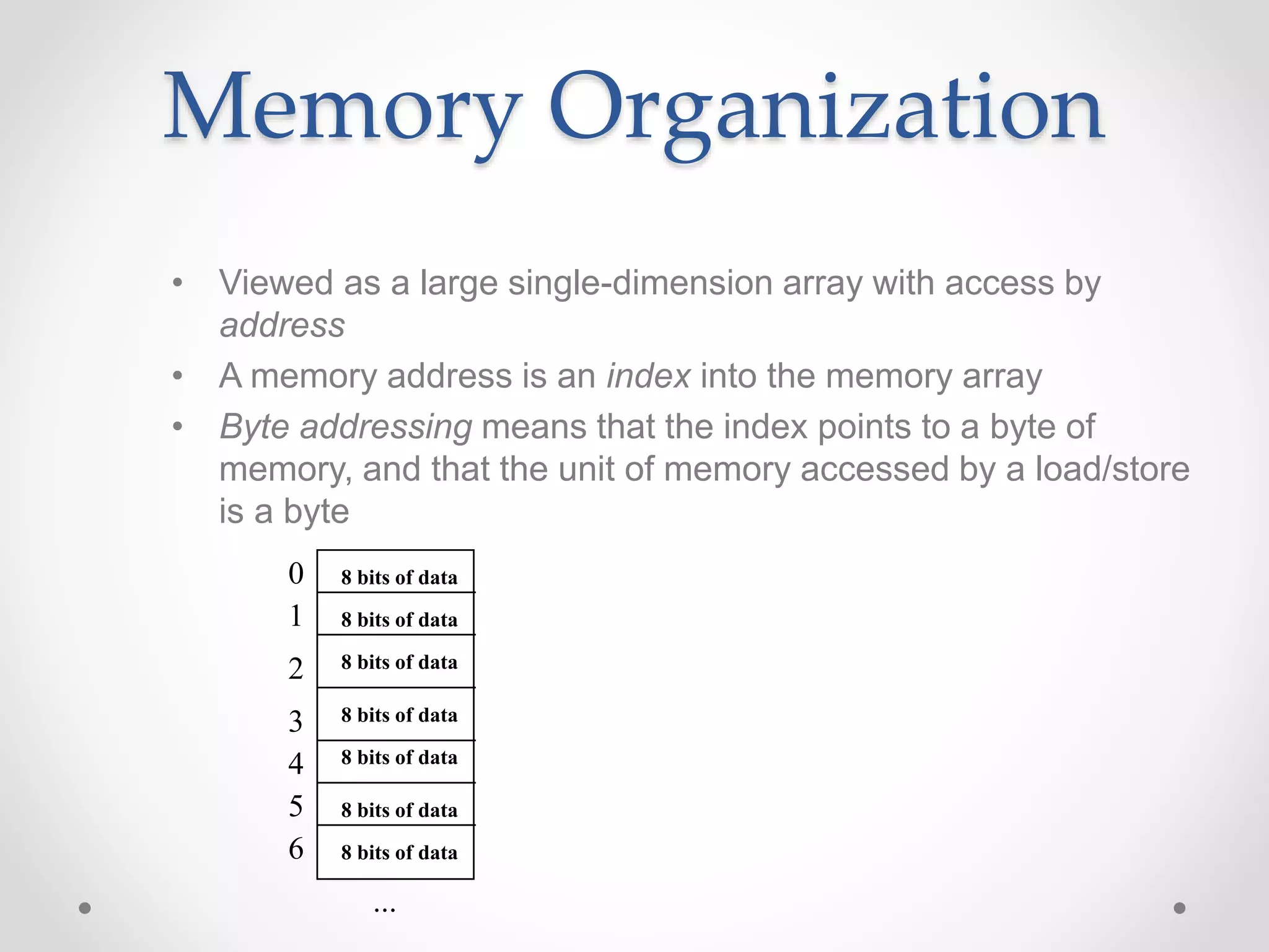
![So far we’ve learned:
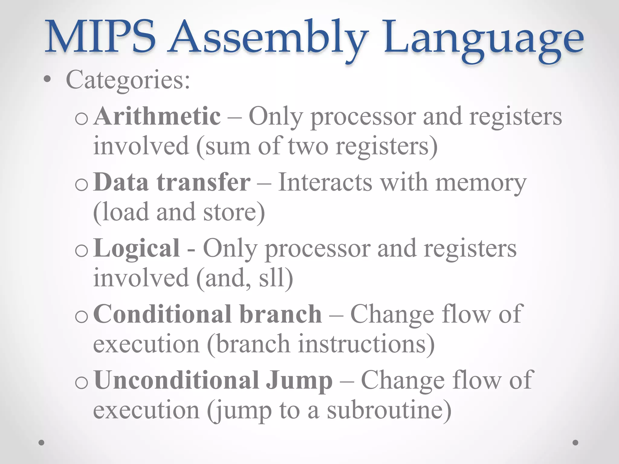
• MIPS
o loading words but addressing bytes
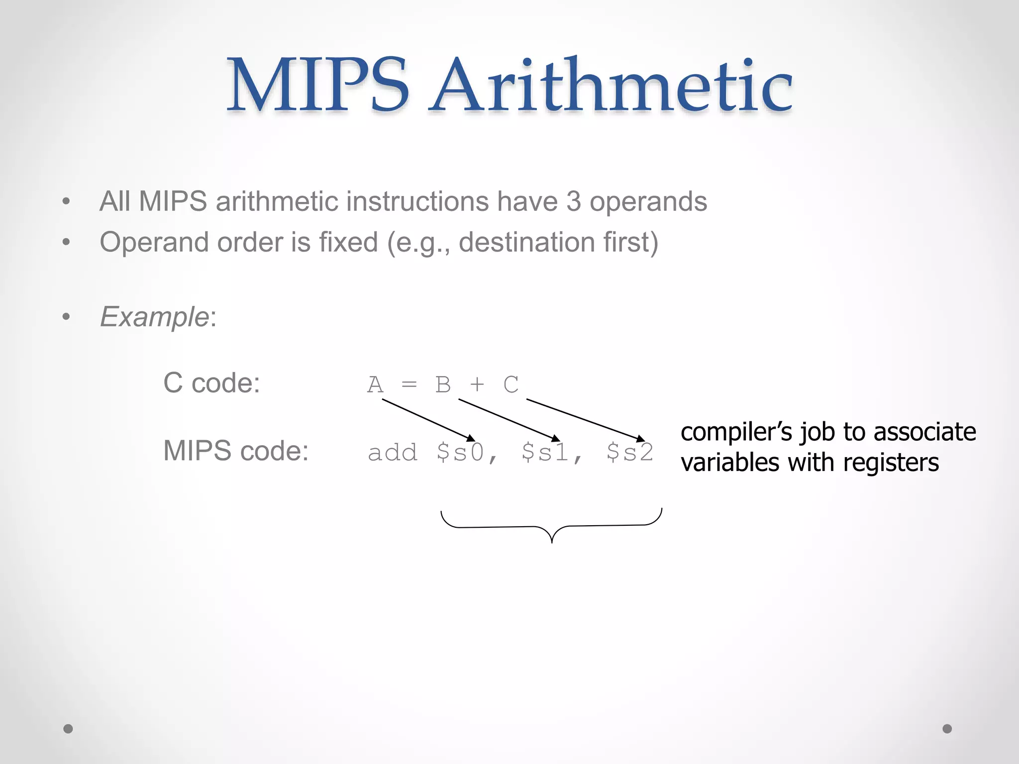
o arithmetic on registers only
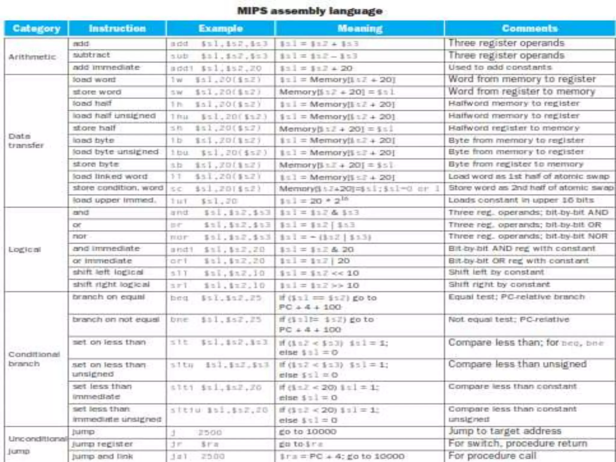
• Instruction Meaning
add $s1, $s2, $s3 $s1 = $s2 + $s3
sub $s1, $s2, $s3 $s1 = $s2 – $s3
lw $s1, 100($s2) $s1 = Memory[$s2+100]
sw $s1, 100($s2) Memory[$s2+100]= $s1
• Try:Find the assembly code of B[8]=A[i]+A[j];
A and B available in $s6 and $s7 respectively
$so-$s5 consists of the values f-j](https://image.slidesharecdn.com/unitica-220307130513/75/Basic-Structure-of-a-Computer-System-57-2048.jpg)
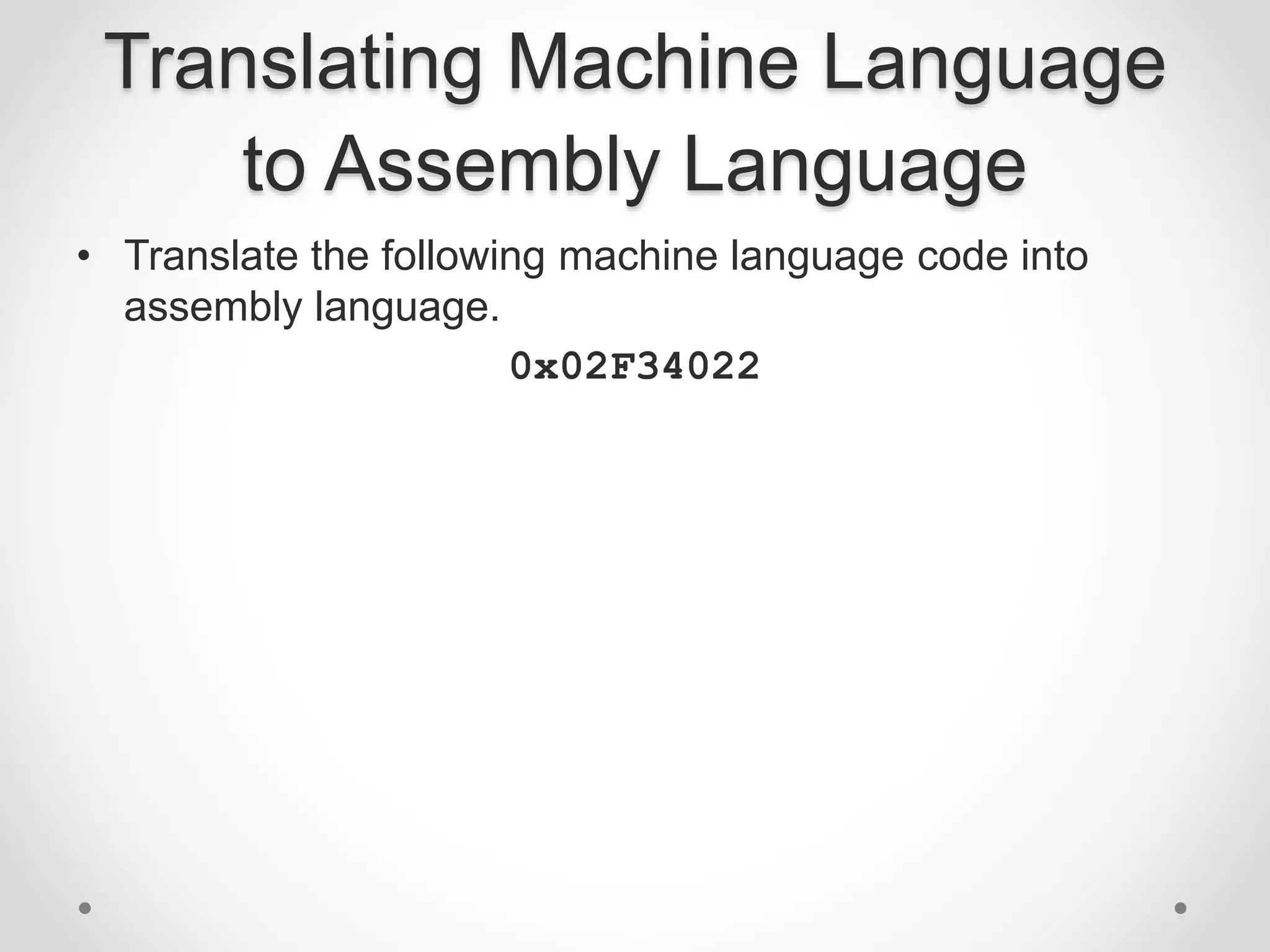
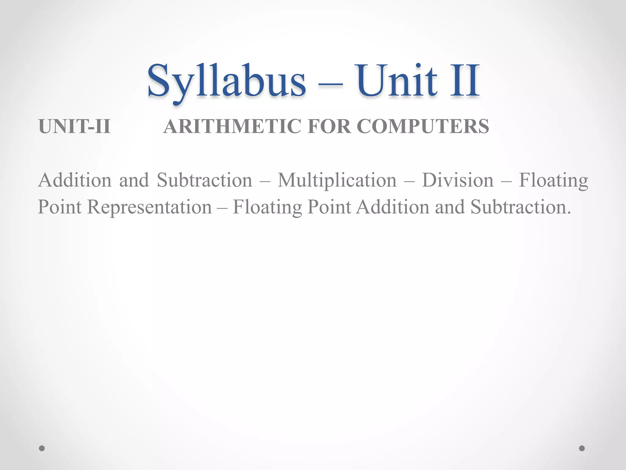
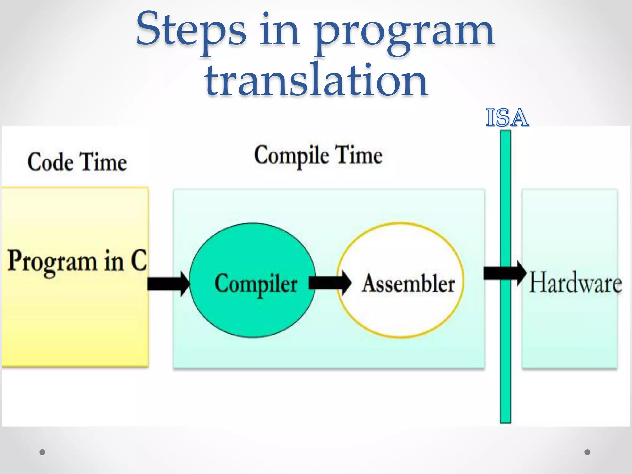
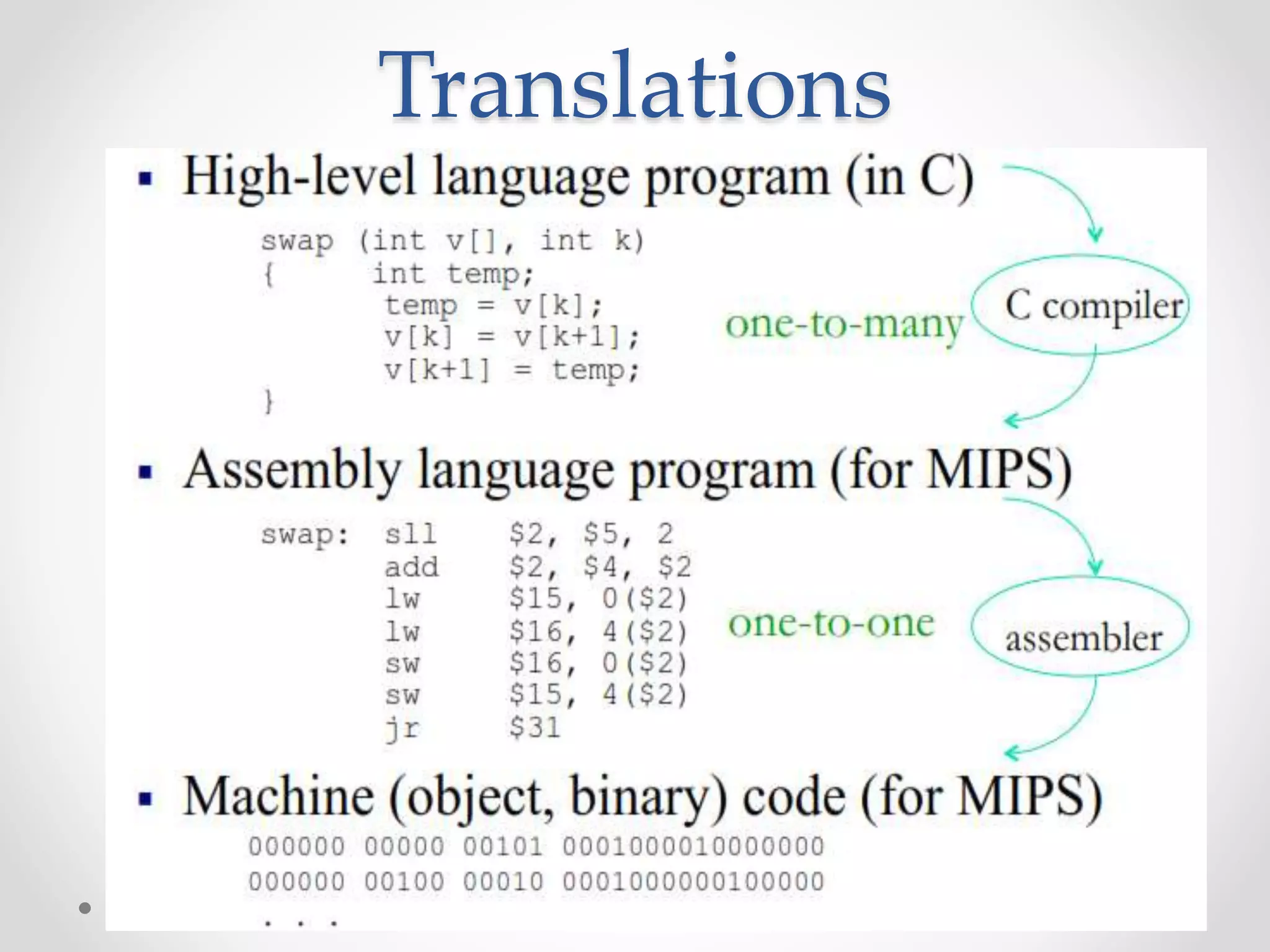
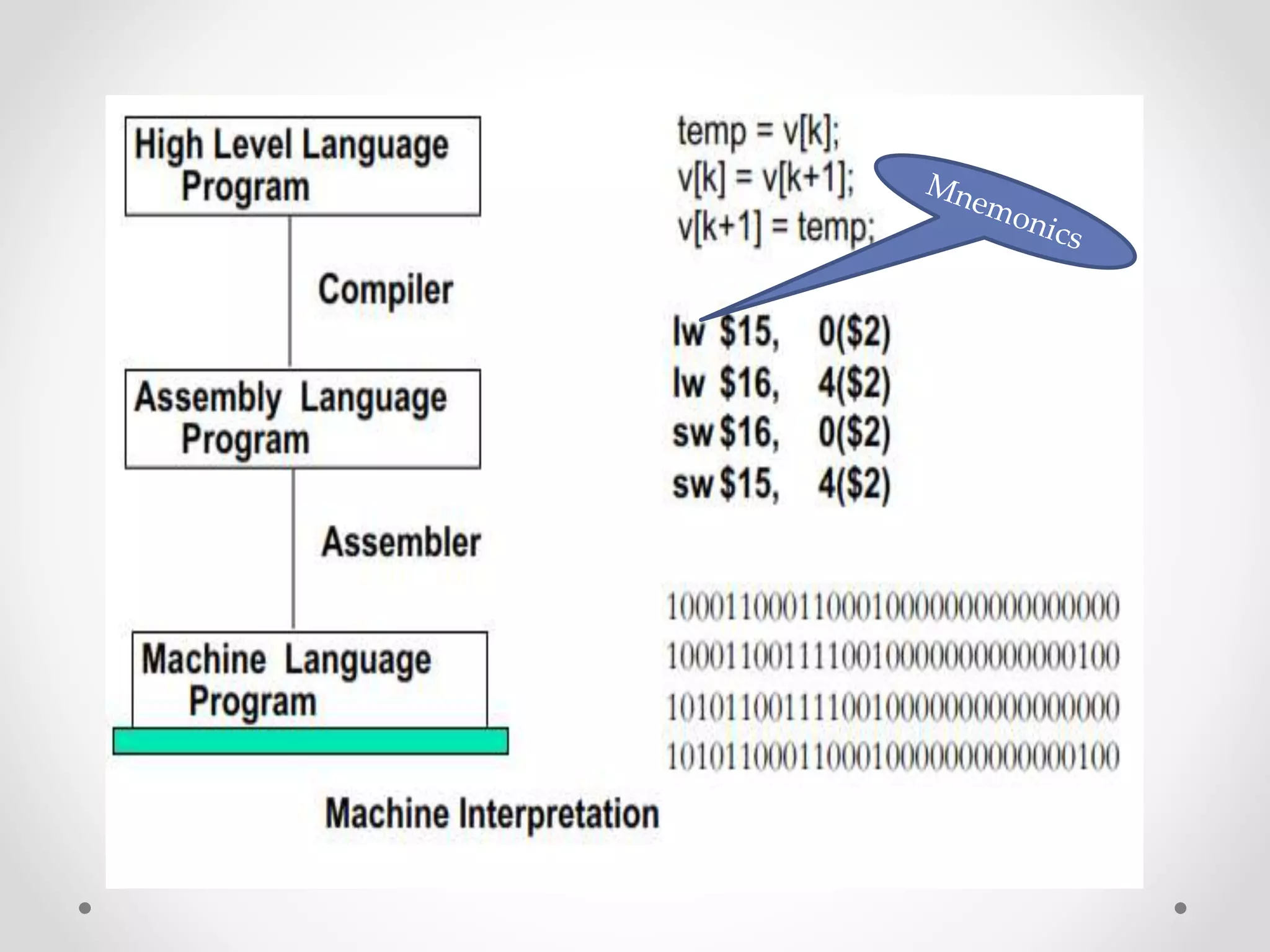
![Translating High level Language
into Machine Language
Q: Consider the following high level statement
A[300] = h + A[300];
If $t1 has the base of the array A and $s2 corresponds to
h, What is the MIPS machine language code?](https://image.slidesharecdn.com/unitica-220307130513/75/Basic-Structure-of-a-Computer-System-73-2048.jpg)
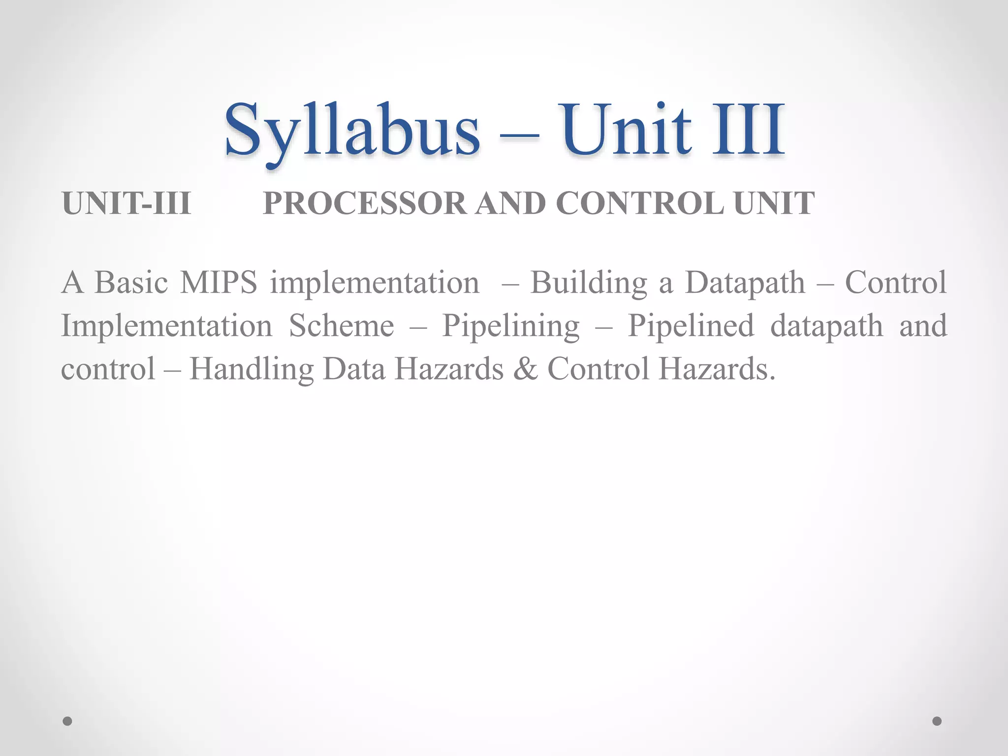
![Compiling a while Loop
in C
while (save[i] == k)
i += 1;
Assume that i and k correspond to registers $s3 and $s5
and the base of the array save is in $s6. What is the MIPS
assembly code corresponding to this C segment?](https://image.slidesharecdn.com/unitica-220307130513/75/Basic-Structure-of-a-Computer-System-85-2048.jpg)
![Compiling a while Loop
in C
while (save[i] == k)
i += 1;
1. load save[i] into a temporary register
1. add i to the base of array save to form the address
2. performs the loop test
1. go to Exit if save[i] ≠ k
3. adds 1 to I
4. back to the while test at the top of the loop
5. Exit](https://image.slidesharecdn.com/unitica-220307130513/75/Basic-Structure-of-a-Computer-System-86-2048.jpg)
![while (save[i] == k)
i += 1;
Assume that i and k correspond to registers $s3 and $s5
and the base of the array save is in $s6. What is the MIPS
assembly code corresponding to this C segment?
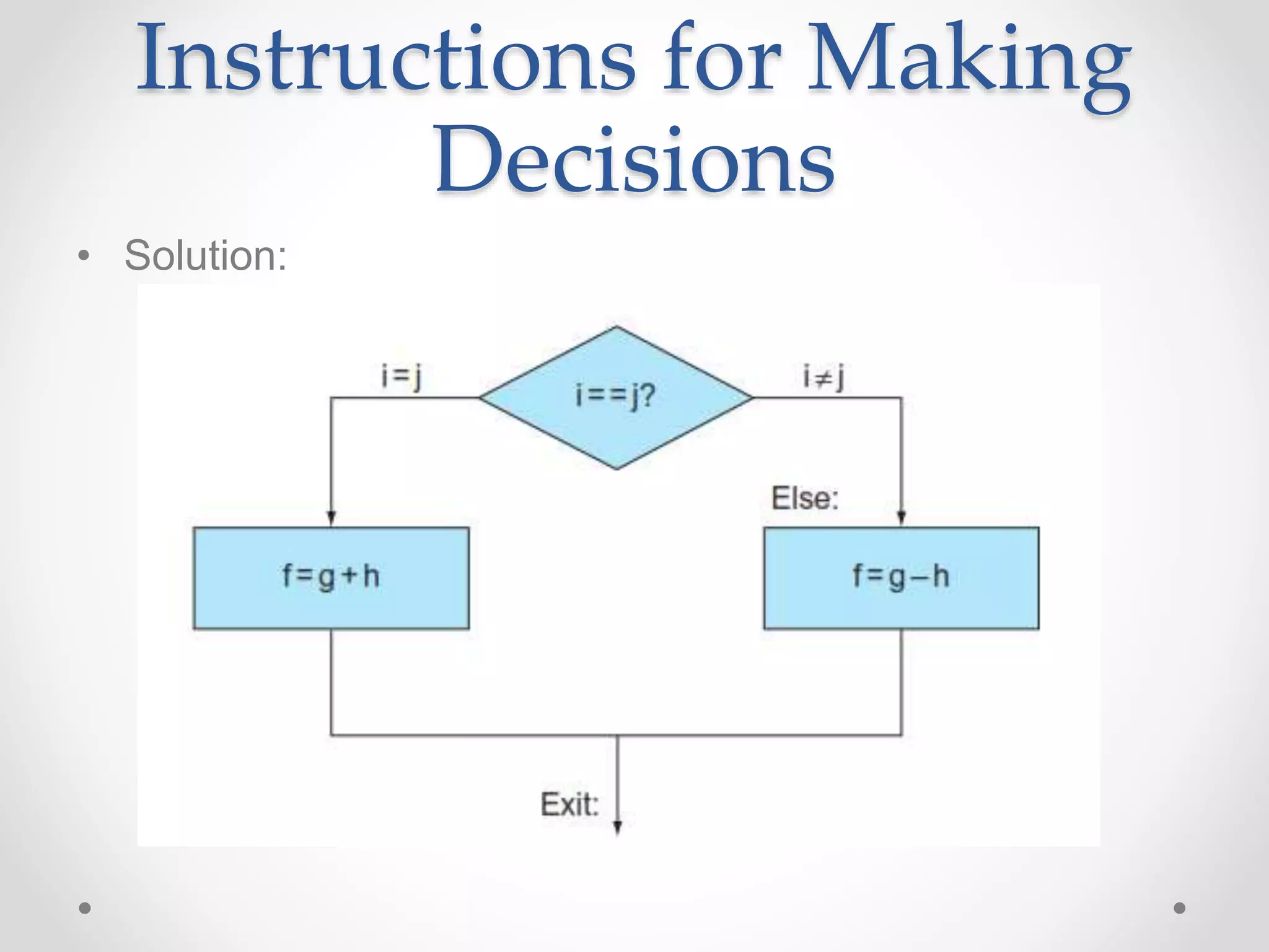
Solution:
Loop: sll $t1,$s3,2 # Temp reg $t1 = i * 4
add $t1,$t1,$s6 # $t1 = address of save[i]
lw $t0,0($t1) # Temp reg $t0 = save[i]
bne $t0,$s5, Exit # go to Exit if save[i] ≠ k
addi $s3,$s3,1 # i = i + 1
j Loop # go to Loop
Exit:](https://image.slidesharecdn.com/unitica-220307130513/75/Basic-Structure-of-a-Computer-System-87-2048.jpg)
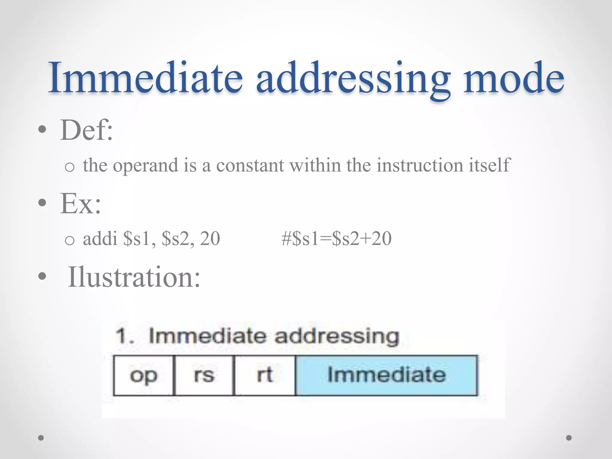
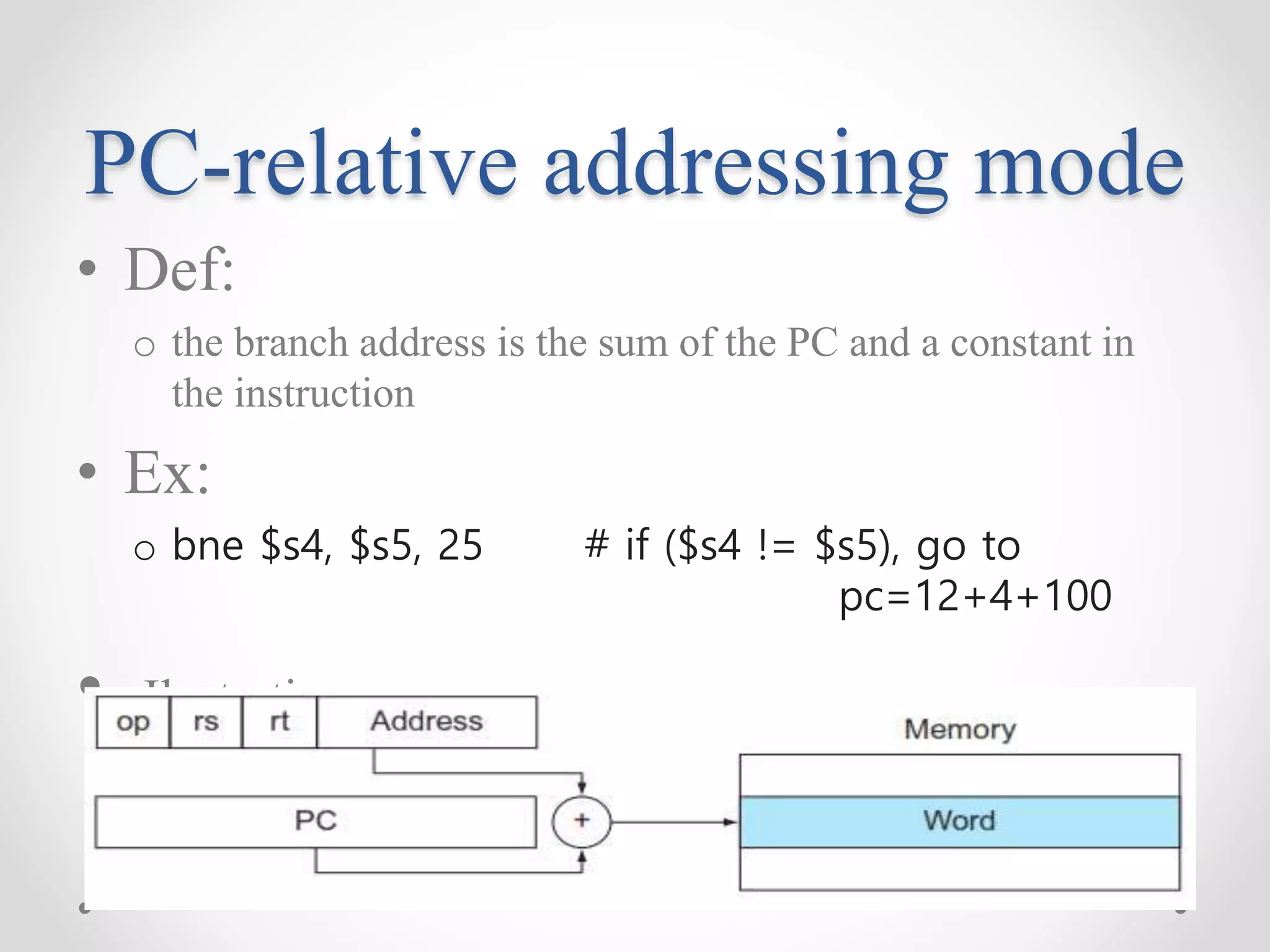
![Base or displacement
addressing mode
• Def:
o the operand is at the memory location whose address is the
sum of a register and a constant in the instruction
o Indirect addressing mode
• Ex:
o lw $s1, 20 ($s3) #$s1= Memory[$s3+20]
• Ilustration:](https://image.slidesharecdn.com/unitica-220307130513/75/Basic-Structure-of-a-Computer-System-91-2048.jpg)