SlideShare a Scribd company logo
1 of 12
Download to read offline
Prashant Sharma, Lecturer, ET&T, MMGGP, Rajnandgaon (C.G.) Page 1
Instruction Set of 8085 microprocessor
a) Data Transfer Group
b) Arithmetic Group
c) Logical Group
d) Branching/Loop Group
e) Stack and Machine Control Group
Notation used in Instruction and opcode
Notations Meaning
M Memory location pointed by HL register pair
R 8-bit register
RP 16-bit register pair
RS Source register
RD Destination register
Addr 16-bit address
X 8-bit data
c) Logical Group
1. ANA R 2. ANA M 3. ANI data 4. ORA R
5. ORA M 6. ORI data 7. XRA R 8. XRA M
9. XRI data 10. CMA 11. CMC 12. STC
13. CMP R 14. CMP M 15. CPI data 16. RLC
17. RRC 18. RAL 19. RAR
1. ANA R
Description - Logical AND content of register R with accumulator A and store
the result in accumulator A.
Operation - A AND R ----> A
No. of Bytes- 1
Flags - S, Z and P are modified to reflect the result of operation. Carry is
reset and AC is set.
Prashant Sharma, Lecturer, ET&T, MMGGP, Rajnandgaon (C.G.) Page 2
Example - ANA E
Before Execution After Execution
R= E = 41H R= E = 41H
A = 35H A = 01H
E = 41H 0100 0001
A = 35H 0011 0101
0000 0001
2. ANA M
Description - Logical AND content of memory location M with accumulator A
and store the result in accumulator A.
Operation - A AND M ----> A OR A AND (HL) ----> A
No. of Bytes- 1
Flags - S, Z and P are modified to reflect the result of operation. Carry is
reset and AC is set.
Example - ANA M
Before Execution After Execution
M= (HL) = (1200) = 41H M= (HL) = (1200) = 41H
A = 35H A = 01H
Note: - AND operation is performed same as ANA R.
3. ANI data
Description - Logical AND immediate data with accumulator A and store the
result in accumulator A.
Operation - A AND data ----> A
No. of Bytes- 2
Flags - S, Z and P are modified to reflect the result of operation. Carry is
reset and AC is set.
Example - ANI 41H
Before Execution After Execution
data = 41H data = 41H
A = 35H A = 01H
Note: - AND operation is performed same as ANA R.
AND Operation
Prashant Sharma, Lecturer, ET&T, MMGGP, Rajnandgaon (C.G.) Page 3
4. ORA R
Description - Logical OR content of register R with accumulator A and store the
result in accumulator A.
Operation - A OR R ----> A
No. of Bytes- 1
Flags - S, Z and P are modified to reflect the result of operation. Carry is
reset and AC is set.
Example - ORA E
Before Execution After Execution
R= E = 41H R= E = 41H
A = 35H A = 75H
E = 41H 0100 0001
A = 35H 0011 0101
0111 0101
5. ORA M
Description - Logical OR content of memory location M with accumulator A
and store the result in accumulator A.
Operation - A OR M ----> A OR A OR (HL) ----> A
No. of Bytes- 1
Flags - S, Z and P are modified to reflect the result of operation. Carry is
reset and AC is set.
Example - ORA M
Before Execution After Execution
M= (HL) = (1200) = 41H M= (HL) = (1200) = 41H
A = 35H A = 75H
Note: - OR operation is performed same as ORA R.
OR Operation
Prashant Sharma, Lecturer, ET&T, MMGGP, Rajnandgaon (C.G.) Page 4
6. ORI data
Description - Logical OR immediate data with accumulator A and store the
result in accumulator A.
Operation - A OR data ----> A
No. of Bytes- 2
Flags - S, Z and P are modified to reflect the result of operation. Carry is
reset and AC is set.
Example - ORI 41H
Before Execution After Execution
data = 41H data = 41H
A = 35H A = 75H
Note: - OR operation is performed same as ORA R.
7. XRA R
Description - Logical X-OR content of register R with accumulator A and store
the result in accumulator A.
Operation - A X-OR R ----> A
No. of Bytes- 1
Flags - S, Z and P are modified to reflect the result of operation. Carry is
reset and AC is set.
Example - XRA E
Before Execution After Execution
R= E = 41H R= E = 41H
A = 35H A = 74H
E = 41H 0100 0001
A = 35H 0011 0101
0111 0100
X-OR Operation
Prashant Sharma, Lecturer, ET&T, MMGGP, Rajnandgaon (C.G.) Page 5
8. XRA M
Description - Logical X-OR content of memory location M with accumulator A
and store the result in accumulator A.
Operation - A X-OR M ----> A OR A X-OR (HL) ----> A
No. of Bytes- 1
Flags - S, Z and P are modified to reflect the result of operation. Carry is
reset and AC is set.
Example - XRA M
Before Execution After Execution
M= (HL) = (1200) = 41H M= (HL) = (1200) = 41H
A = 35H A = 74H
Note: - X-OR operation is performed same as XRA R.
9. XRI data
Description - Logical X-OR immediate data with accumulator A and store the
result in accumulator A.
Operation - A X-OR data ----> A
No. of Bytes- 2
Flags - S, Z and P are modified to reflect the result of operation. Carry is
reset and AC is set.
Example - XRI 41H
Before Execution After Execution
data = 41H data = 41H
A = 35H A = 74H
Note: - X-OR operation is performed same as XRA R.
Prashant Sharma, Lecturer, ET&T, MMGGP, Rajnandgaon (C.G.) Page 6
10. CMA
Description - Complement accumulator A and store the result in accumulator
A.
Operation - A̅ ----> A
No. of Bytes- 1
Flags - No flags are modified.
Example - CMA
Before Execution After Execution
A = 35H A = CA H
A = 35H = 0011 0101
A̅ = CA H = 1100 1010
11.CMC
Description - Complement the carry flag.
Operation - CY̅̅̅̅----> CY
No. of Bytes- 1
Flags - Only carry flag is complemented. No other flags are modified.
Example - CMC
Before Execution After Execution
(i) CY = Set CY = Reset
(ii) CY = Reset CY = Set
12.STC
Description - Set the carry flag.
Operation - CY = Set
No. of Bytes- 1
Flags - Only carry flag is complemented. No other flags are modified.
Example - STC
Before Execution After Execution
(i) CY = Set CY = Set
(ii) CY = Reset CY = Set
Prashant Sharma, Lecturer, ET&T, MMGGP, Rajnandgaon (C.G.) Page 7
13.CMP R
Description - Compare content of register R with accumulator A. The contents
of register R and accumulator A are not altered.
Operation - A compare R----> Flag Register
No. of Bytes- 1
Flags - S, Z and P are modified to reflect the result of operation and Z, CY
are used to indicate the result of comparison.
(i) A > R: CY is Reset and Zero flag is Reset.
(ii) A = R: Zero flag is set.
(iii) A < R: CY flag is set.
Example - CMP D
Before Execution After Execution
(i) A = 35H A > D
D = 25H
A = 35H = 0011 0101
D = 25H = 0010 0101
2’s complement of 25H -----> 1101 1011
A = 35H = 0011 0101
2’s complement of 25H -----> + 1101 1011
1 0001 0000
Carry is generated so CY = set, microprocessor complement this carry so CY = reset
and also zero flag is reset, which represent that the A is greater than D.
(ii) A = 35H A = D
D = 35H
A = 35H = 0011 0101
D = 35H = 0011 0101
2’s complement of 35H -----> 1100 1011
A = 35H = 0011 0101
2’s complement of 35H -----> + 1100 1011
1 0000 0000
Carry is generated so CY = set, microprocessor complement this carry so CY = reset
and zero flag is set, which represent that the A is equal to D.
Prashant Sharma, Lecturer, ET&T, MMGGP, Rajnandgaon (C.G.) Page 8
(iii) A = 25H A < D
D = 35H
A = 25H = 0010 0101
D = 35H = 0011 0101
2’s complement of 35H -----> 1100 1011
A = 25H = 0010 0101
2’s complement of 35H -----> + 1100 1011
1111 0000
No carry generated so CY = reset, microprocessor complement this carry so CY = set,
which represent that the A is less than D.
14.CMP M
Description - Compare content of memory location M with accumulator A. The
contents of memory location M and accumulator A are not altered.
Operation - A compare M----> Flag Register
OR
A compare (HL)----> Flag Register
No. of Bytes- 1
Flags - S, Z and P are modified to reflect the result of operation and Z, CY
are used to indicate the result of comparison.
(i) A > M: CY is Reset and Zero flag is Reset.
(ii) A = M: Zero flag is set.
(iii) A < M: CY flag is set.
Example - CMP M
Before Execution After Execution
A = 35H A > M
M = (HL) = (1000) = 25H
A = 35H = 0011 0101
M = (HL) = (1000) = 25H = 0010 0101
2’s complement of 25H -----> 1101 1011
Prashant Sharma, Lecturer, ET&T, MMGGP, Rajnandgaon (C.G.) Page 9
A = 35H = 0011 0101
2’s complement of 25H -----> + 1101 1011
1 0001 0000
Carry is generated so CY = set, microprocessor complement this carry so CY = reset
and also zero flag is reset, which represent that the A is greater than M.
Note: - Other comparison examples (A=M & A<M) are same as CMP R.
15.CPI data
Description - Compare immediate data with accumulator A. The immediate
and accumulator A are not altered.
Operation - A compare data----> Flag Register
No. of Bytes- 2
Flags - S, Z and P are modified to reflect the result of operation and Z, CY
are used to indicate the result of comparison.
(i) A > data: CY is Reset and Zero flag is Reset.
(ii) A = data: Zero flag is set.
(iii) A < data: CY flag is set.
Example - CPI 25H
Before Execution After Execution
A = 35H A > data
data = 25H
A = 35H = 0011 0101
data = 25H = 0010 0101
2’s complement of 25H -----> 1101 1011
A = 35H = 0011 0101
2’s complement of 25H -----> + 1101 1011
1 0001 0000
Carry is generated so CY = set, microprocessor complement this carry so CY = reset
and also zero flag is reset, which represent that the A is greater than immediate
data.
Note: - Other comparison examples (A=data & A<data) are same as CMP R.
Prashant Sharma, Lecturer, ET&T, MMGGP, Rajnandgaon (C.G.) Page 10
16. RLC
Description - Rotate accumulator A left by 1 bit.
Operation - Accumulator: Dn Dn+1 (n=0 to 6)
D7 D0
D7 CY
No. of Bytes- 1
Flags - Only carry flag is modified. No other flags are modified.
Example - RLC
Before Execution After Execution
A = 48H A = 90H
CY = 0
Value D7 D6 D5 D4 D3 D2 D1 D0
A = 48H 0 1 0 0 1 0 0 0
A = 91H 1 0 0 1 0 0 0 0
17. RRC
Description - Rotate accumulator A right by 1 bit.
Operation - Accumulator: Dn+1 Dn (n=0 to 6)
D0 D7
D0 CY
No. of Bytes- 1
Flags - Only carry flag is modified. No other flags are modified.
Example - RRC
D7 D6 D5 D4 D3 D2 D1 D0
CY
CY = 0
CY
Prashant Sharma, Lecturer, ET&T, MMGGP, Rajnandgaon (C.G.) Page 11
Before Execution After Execution
A = 48H A = 24H
CY = 0
Value D7 D6 D5 D4 D3 D2 D1 D0
A = 48H 0 1 0 0 1 0 0 0
A = 24H 0 0 1 0 0 1 0 0
18. RAL
Description - Rotate accumulator A left through carry by 1 bit.
Operation - Accumulator: Dn Dn+1 (n=0 to 6)
D7 CY
CY D0
No. of Bytes- 1
Flags - Only carry flag is modified. No other flags are modified.
Example - RAL
Before Execution After Execution
A = 58H A = B1H
CY = 1 CY = 0
Value D7 D6 D5 D4 D3 D2 D1 D0
A = 58H 0 1 0 1 1 0 0 0
A = B1H 1 0 1 1 0 0 0 1
CY=1
New Value Previous Value
D7 D6 D5 D4 D3 D2 D1 D0
CY = 0
CY
CY = 0
Prashant Sharma, Lecturer, ET&T, MMGGP, Rajnandgaon (C.G.) Page 12
19. RAR
Description - Rotate accumulator A right through carry by 1 bit.
Operation - Accumulator: Dn+1 Dn (n=0 to 6)
D0 CY
CY D7
No. of Bytes- 1
Flags - Only carry flag is modified. No other flags are modified.
Example - RAR
Before Execution After Execution
A = 59H A = 2C H
CY = 0 CY = 1
Value D7 D6 D5 D4 D3 D2 D1 D0
A = 59H 0 1 0 1 1 0 0 1
A = 2C H 0 0 1 0 1 1 0 0
CY=0
Previous Value New Value
D7 D6 D5 D4 D3 D2 D1 D0
CY
CY = 1

More Related Content

What's hot

Types of Addressing modes- COA
Types of Addressing modes- COATypes of Addressing modes- COA
Types of Addressing modes- COA
Ruchi Maurya
 
Instruction set of 8086
Instruction set of 8086Instruction set of 8086
Instruction set of 8086
9840596838
 

What's hot (20)

Addressing modes of 8085
Addressing modes of 8085Addressing modes of 8085
Addressing modes of 8085
 
MICROPROCESSOR INSTRUCTION SET OF 8085
MICROPROCESSOR INSTRUCTION SET OF 8085MICROPROCESSOR INSTRUCTION SET OF 8085
MICROPROCESSOR INSTRUCTION SET OF 8085
 
8085 Paper Presentation slides,ppt,microprocessor 8085 ,guide, instruction set
8085 Paper Presentation slides,ppt,microprocessor 8085 ,guide, instruction set8085 Paper Presentation slides,ppt,microprocessor 8085 ,guide, instruction set
8085 Paper Presentation slides,ppt,microprocessor 8085 ,guide, instruction set
 
Computer architecture pipelining
Computer architecture pipeliningComputer architecture pipelining
Computer architecture pipelining
 
8085 micro processor
8085 micro processor8085 micro processor
8085 micro processor
 
Types of Addressing modes- COA
Types of Addressing modes- COATypes of Addressing modes- COA
Types of Addressing modes- COA
 
Assembly language programming_fundamentals 8086
Assembly language programming_fundamentals 8086Assembly language programming_fundamentals 8086
Assembly language programming_fundamentals 8086
 
Instruction set of 8086
Instruction set of 8086Instruction set of 8086
Instruction set of 8086
 
Instruction set of 8086 Microprocessor
Instruction set of 8086 Microprocessor Instruction set of 8086 Microprocessor
Instruction set of 8086 Microprocessor
 
Timing Diagram of MVI Instruction of 8085 Microprocessor
Timing Diagram of MVI Instruction of 8085 MicroprocessorTiming Diagram of MVI Instruction of 8085 Microprocessor
Timing Diagram of MVI Instruction of 8085 Microprocessor
 
Lic lab manual
Lic lab manualLic lab manual
Lic lab manual
 
ARITHMETIC OPERATIONS IN 8085 MICROPROCESSOR
ARITHMETIC OPERATIONS IN 8085 MICROPROCESSORARITHMETIC OPERATIONS IN 8085 MICROPROCESSOR
ARITHMETIC OPERATIONS IN 8085 MICROPROCESSOR
 
DSP_2018_FOEHU - Lec 06 - FIR Filter Design
DSP_2018_FOEHU - Lec 06 - FIR Filter DesignDSP_2018_FOEHU - Lec 06 - FIR Filter Design
DSP_2018_FOEHU - Lec 06 - FIR Filter Design
 
Microcontroller instruction set
Microcontroller instruction setMicrocontroller instruction set
Microcontroller instruction set
 
basic computer programming and micro programmed control
basic computer programming and micro programmed controlbasic computer programming and micro programmed control
basic computer programming and micro programmed control
 
8086 Microprocessor
8086  Microprocessor8086  Microprocessor
8086 Microprocessor
 
LOGICAL OPERATIONS IN 8085 MICROPROCESSOR
LOGICAL OPERATIONS IN 8085 MICROPROCESSORLOGICAL OPERATIONS IN 8085 MICROPROCESSOR
LOGICAL OPERATIONS IN 8085 MICROPROCESSOR
 
Motorola microprocessor
Motorola microprocessorMotorola microprocessor
Motorola microprocessor
 
Unit I.fundamental of Programmable DSP
Unit I.fundamental of Programmable DSPUnit I.fundamental of Programmable DSP
Unit I.fundamental of Programmable DSP
 
SAP II ARTICTURE ,SAP 2
SAP II ARTICTURE ,SAP 2SAP II ARTICTURE ,SAP 2
SAP II ARTICTURE ,SAP 2
 

Similar to 8085 logical instruction

8085 instruction set.pptx
8085 instruction set.pptx8085 instruction set.pptx
8085 instruction set.pptx
AchintKaur27
 
Instruction 4.pptx
Instruction 4.pptxInstruction 4.pptx
Instruction 4.pptx
HebaEng
 

Similar to 8085 logical instruction (20)

Microprocessor 11el01
Microprocessor 11el01Microprocessor 11el01
Microprocessor 11el01
 
Lecture 04 Logical Group of Instructions
Lecture 04 Logical Group of InstructionsLecture 04 Logical Group of Instructions
Lecture 04 Logical Group of Instructions
 
Instruction set 8085
Instruction set 8085Instruction set 8085
Instruction set 8085
 
Logical instruction of 8085
Logical instruction of 8085 Logical instruction of 8085
Logical instruction of 8085
 
Lecture 03 Arithmetic Group of Instructions
Lecture 03 Arithmetic Group of InstructionsLecture 03 Arithmetic Group of Instructions
Lecture 03 Arithmetic Group of Instructions
 
REGISTER TRANSFER AND MICROOPERATIONS2017-3-5.ppt
REGISTER  TRANSFER  AND  MICROOPERATIONS2017-3-5.pptREGISTER  TRANSFER  AND  MICROOPERATIONS2017-3-5.ppt
REGISTER TRANSFER AND MICROOPERATIONS2017-3-5.ppt
 
8085 instruction set.pptx
8085 instruction set.pptx8085 instruction set.pptx
8085 instruction set.pptx
 
Logical instruction of 8085
Logical instruction of 8085Logical instruction of 8085
Logical instruction of 8085
 
5. 8085 instruction set ii
5. 8085 instruction set ii5. 8085 instruction set ii
5. 8085 instruction set ii
 
INTEL 8085 DATA FORMAT AND INSTRUCTIONS
INTEL 8085 DATA FORMAT AND INSTRUCTIONSINTEL 8085 DATA FORMAT AND INSTRUCTIONS
INTEL 8085 DATA FORMAT AND INSTRUCTIONS
 
Chapter 3 instruction set-of-8085
Chapter 3 instruction set-of-8085Chapter 3 instruction set-of-8085
Chapter 3 instruction set-of-8085
 
module 5.1.pptx
module 5.1.pptxmodule 5.1.pptx
module 5.1.pptx
 
module 5.pptx
module 5.pptxmodule 5.pptx
module 5.pptx
 
Register transfer &amp; microoperations moris mano ch 04
Register transfer &amp; microoperations    moris mano ch 04Register transfer &amp; microoperations    moris mano ch 04
Register transfer &amp; microoperations moris mano ch 04
 
Instruction set of 8085
Instruction set of 8085Instruction set of 8085
Instruction set of 8085
 
8085 instruction set (detailed)
8085 instruction set (detailed)8085 instruction set (detailed)
8085 instruction set (detailed)
 
Instruction 4.pptx
Instruction 4.pptxInstruction 4.pptx
Instruction 4.pptx
 
Mpi
MpiMpi
Mpi
 
8085 instruction set
8085 instruction set8085 instruction set
8085 instruction set
 
Dsp Datapath
Dsp DatapathDsp Datapath
Dsp Datapath
 

Recently uploaded

Hospital management system project report.pdf
Hospital management system project report.pdfHospital management system project report.pdf
Hospital management system project report.pdf
Kamal Acharya
 
Integrated Test Rig For HTFE-25 - Neometrix
Integrated Test Rig For HTFE-25 - NeometrixIntegrated Test Rig For HTFE-25 - Neometrix
Integrated Test Rig For HTFE-25 - Neometrix
Neometrix_Engineering_Pvt_Ltd
 
scipt v1.pptxcxxxxxxxxxxxxxxxxxxxxxxxxxxxxxxxxxxxxxxxxxxxxxxxxxxxxxxxxxxxxxxx...
scipt v1.pptxcxxxxxxxxxxxxxxxxxxxxxxxxxxxxxxxxxxxxxxxxxxxxxxxxxxxxxxxxxxxxxxx...scipt v1.pptxcxxxxxxxxxxxxxxxxxxxxxxxxxxxxxxxxxxxxxxxxxxxxxxxxxxxxxxxxxxxxxxx...
scipt v1.pptxcxxxxxxxxxxxxxxxxxxxxxxxxxxxxxxxxxxxxxxxxxxxxxxxxxxxxxxxxxxxxxxx...
HenryBriggs2
 

Recently uploaded (20)

Introduction to Data Visualization,Matplotlib.pdf
Introduction to Data Visualization,Matplotlib.pdfIntroduction to Data Visualization,Matplotlib.pdf
Introduction to Data Visualization,Matplotlib.pdf
 
Augmented Reality (AR) with Augin Software.pptx
Augmented Reality (AR) with Augin Software.pptxAugmented Reality (AR) with Augin Software.pptx
Augmented Reality (AR) with Augin Software.pptx
 
Signal Processing and Linear System Analysis
Signal Processing and Linear System AnalysisSignal Processing and Linear System Analysis
Signal Processing and Linear System Analysis
 
COST-EFFETIVE and Energy Efficient BUILDINGS ptx
COST-EFFETIVE  and Energy Efficient BUILDINGS ptxCOST-EFFETIVE  and Energy Efficient BUILDINGS ptx
COST-EFFETIVE and Energy Efficient BUILDINGS ptx
 
Hospital management system project report.pdf
Hospital management system project report.pdfHospital management system project report.pdf
Hospital management system project report.pdf
 
Introduction to Artificial Intelligence ( AI)
Introduction to Artificial Intelligence ( AI)Introduction to Artificial Intelligence ( AI)
Introduction to Artificial Intelligence ( AI)
 
Integrated Test Rig For HTFE-25 - Neometrix
Integrated Test Rig For HTFE-25 - NeometrixIntegrated Test Rig For HTFE-25 - Neometrix
Integrated Test Rig For HTFE-25 - Neometrix
 
Computer Graphics Introduction To Curves
Computer Graphics Introduction To CurvesComputer Graphics Introduction To Curves
Computer Graphics Introduction To Curves
 
Computer Networks Basics of Network Devices
Computer Networks  Basics of Network DevicesComputer Networks  Basics of Network Devices
Computer Networks Basics of Network Devices
 
scipt v1.pptxcxxxxxxxxxxxxxxxxxxxxxxxxxxxxxxxxxxxxxxxxxxxxxxxxxxxxxxxxxxxxxxx...
scipt v1.pptxcxxxxxxxxxxxxxxxxxxxxxxxxxxxxxxxxxxxxxxxxxxxxxxxxxxxxxxxxxxxxxxx...scipt v1.pptxcxxxxxxxxxxxxxxxxxxxxxxxxxxxxxxxxxxxxxxxxxxxxxxxxxxxxxxxxxxxxxxx...
scipt v1.pptxcxxxxxxxxxxxxxxxxxxxxxxxxxxxxxxxxxxxxxxxxxxxxxxxxxxxxxxxxxxxxxxx...
 
Convergence of Robotics and Gen AI offers excellent opportunities for Entrepr...
Convergence of Robotics and Gen AI offers excellent opportunities for Entrepr...Convergence of Robotics and Gen AI offers excellent opportunities for Entrepr...
Convergence of Robotics and Gen AI offers excellent opportunities for Entrepr...
 
Online electricity billing project report..pdf
Online electricity billing project report..pdfOnline electricity billing project report..pdf
Online electricity billing project report..pdf
 
8086 Microprocessor Architecture: 16-bit microprocessor
8086 Microprocessor Architecture: 16-bit microprocessor8086 Microprocessor Architecture: 16-bit microprocessor
8086 Microprocessor Architecture: 16-bit microprocessor
 
Employee leave management system project.
Employee leave management system project.Employee leave management system project.
Employee leave management system project.
 
Post office management system project ..pdf
Post office management system project ..pdfPost office management system project ..pdf
Post office management system project ..pdf
 
fitting shop and tools used in fitting shop .ppt
fitting shop and tools used in fitting shop .pptfitting shop and tools used in fitting shop .ppt
fitting shop and tools used in fitting shop .ppt
 
HOA1&2 - Module 3 - PREHISTORCI ARCHITECTURE OF KERALA.pptx
HOA1&2 - Module 3 - PREHISTORCI ARCHITECTURE OF KERALA.pptxHOA1&2 - Module 3 - PREHISTORCI ARCHITECTURE OF KERALA.pptx
HOA1&2 - Module 3 - PREHISTORCI ARCHITECTURE OF KERALA.pptx
 
HAND TOOLS USED AT ELECTRONICS WORK PRESENTED BY KOUSTAV SARKAR
HAND TOOLS USED AT ELECTRONICS WORK PRESENTED BY KOUSTAV SARKARHAND TOOLS USED AT ELECTRONICS WORK PRESENTED BY KOUSTAV SARKAR
HAND TOOLS USED AT ELECTRONICS WORK PRESENTED BY KOUSTAV SARKAR
 
Max. shear stress theory-Maximum Shear Stress Theory ​ Maximum Distortional ...
Max. shear stress theory-Maximum Shear Stress Theory ​  Maximum Distortional ...Max. shear stress theory-Maximum Shear Stress Theory ​  Maximum Distortional ...
Max. shear stress theory-Maximum Shear Stress Theory ​ Maximum Distortional ...
 
Online food ordering system project report.pdf
Online food ordering system project report.pdfOnline food ordering system project report.pdf
Online food ordering system project report.pdf
 

8085 logical instruction

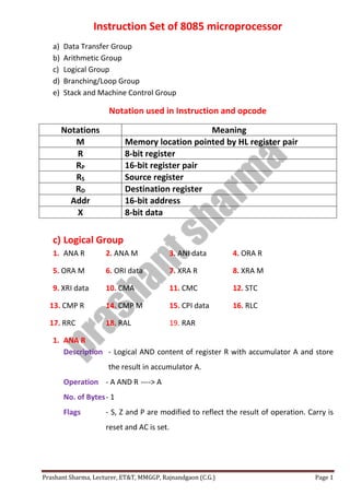
  • 1. Prashant Sharma, Lecturer, ET&T, MMGGP, Rajnandgaon (C.G.) Page 1 Instruction Set of 8085 microprocessor a) Data Transfer Group b) Arithmetic Group c) Logical Group d) Branching/Loop Group e) Stack and Machine Control Group Notation used in Instruction and opcode Notations Meaning M Memory location pointed by HL register pair R 8-bit register RP 16-bit register pair RS Source register RD Destination register Addr 16-bit address X 8-bit data c) Logical Group 1. ANA R 2. ANA M 3. ANI data 4. ORA R 5. ORA M 6. ORI data 7. XRA R 8. XRA M 9. XRI data 10. CMA 11. CMC 12. STC 13. CMP R 14. CMP M 15. CPI data 16. RLC 17. RRC 18. RAL 19. RAR 1. ANA R Description - Logical AND content of register R with accumulator A and store the result in accumulator A. Operation - A AND R ----> A No. of Bytes- 1 Flags - S, Z and P are modified to reflect the result of operation. Carry is reset and AC is set.
  • 2. Prashant Sharma, Lecturer, ET&T, MMGGP, Rajnandgaon (C.G.) Page 2 Example - ANA E Before Execution After Execution R= E = 41H R= E = 41H A = 35H A = 01H E = 41H 0100 0001 A = 35H 0011 0101 0000 0001 2. ANA M Description - Logical AND content of memory location M with accumulator A and store the result in accumulator A. Operation - A AND M ----> A OR A AND (HL) ----> A No. of Bytes- 1 Flags - S, Z and P are modified to reflect the result of operation. Carry is reset and AC is set. Example - ANA M Before Execution After Execution M= (HL) = (1200) = 41H M= (HL) = (1200) = 41H A = 35H A = 01H Note: - AND operation is performed same as ANA R. 3. ANI data Description - Logical AND immediate data with accumulator A and store the result in accumulator A. Operation - A AND data ----> A No. of Bytes- 2 Flags - S, Z and P are modified to reflect the result of operation. Carry is reset and AC is set. Example - ANI 41H Before Execution After Execution data = 41H data = 41H A = 35H A = 01H Note: - AND operation is performed same as ANA R. AND Operation
  • 3. Prashant Sharma, Lecturer, ET&T, MMGGP, Rajnandgaon (C.G.) Page 3 4. ORA R Description - Logical OR content of register R with accumulator A and store the result in accumulator A. Operation - A OR R ----> A No. of Bytes- 1 Flags - S, Z and P are modified to reflect the result of operation. Carry is reset and AC is set. Example - ORA E Before Execution After Execution R= E = 41H R= E = 41H A = 35H A = 75H E = 41H 0100 0001 A = 35H 0011 0101 0111 0101 5. ORA M Description - Logical OR content of memory location M with accumulator A and store the result in accumulator A. Operation - A OR M ----> A OR A OR (HL) ----> A No. of Bytes- 1 Flags - S, Z and P are modified to reflect the result of operation. Carry is reset and AC is set. Example - ORA M Before Execution After Execution M= (HL) = (1200) = 41H M= (HL) = (1200) = 41H A = 35H A = 75H Note: - OR operation is performed same as ORA R. OR Operation
  • 4. Prashant Sharma, Lecturer, ET&T, MMGGP, Rajnandgaon (C.G.) Page 4 6. ORI data Description - Logical OR immediate data with accumulator A and store the result in accumulator A. Operation - A OR data ----> A No. of Bytes- 2 Flags - S, Z and P are modified to reflect the result of operation. Carry is reset and AC is set. Example - ORI 41H Before Execution After Execution data = 41H data = 41H A = 35H A = 75H Note: - OR operation is performed same as ORA R. 7. XRA R Description - Logical X-OR content of register R with accumulator A and store the result in accumulator A. Operation - A X-OR R ----> A No. of Bytes- 1 Flags - S, Z and P are modified to reflect the result of operation. Carry is reset and AC is set. Example - XRA E Before Execution After Execution R= E = 41H R= E = 41H A = 35H A = 74H E = 41H 0100 0001 A = 35H 0011 0101 0111 0100 X-OR Operation
  • 5. Prashant Sharma, Lecturer, ET&T, MMGGP, Rajnandgaon (C.G.) Page 5 8. XRA M Description - Logical X-OR content of memory location M with accumulator A and store the result in accumulator A. Operation - A X-OR M ----> A OR A X-OR (HL) ----> A No. of Bytes- 1 Flags - S, Z and P are modified to reflect the result of operation. Carry is reset and AC is set. Example - XRA M Before Execution After Execution M= (HL) = (1200) = 41H M= (HL) = (1200) = 41H A = 35H A = 74H Note: - X-OR operation is performed same as XRA R. 9. XRI data Description - Logical X-OR immediate data with accumulator A and store the result in accumulator A. Operation - A X-OR data ----> A No. of Bytes- 2 Flags - S, Z and P are modified to reflect the result of operation. Carry is reset and AC is set. Example - XRI 41H Before Execution After Execution data = 41H data = 41H A = 35H A = 74H Note: - X-OR operation is performed same as XRA R.
  • 6. Prashant Sharma, Lecturer, ET&T, MMGGP, Rajnandgaon (C.G.) Page 6 10. CMA Description - Complement accumulator A and store the result in accumulator A. Operation - A̅ ----> A No. of Bytes- 1 Flags - No flags are modified. Example - CMA Before Execution After Execution A = 35H A = CA H A = 35H = 0011 0101 A̅ = CA H = 1100 1010 11.CMC Description - Complement the carry flag. Operation - CY̅̅̅̅----> CY No. of Bytes- 1 Flags - Only carry flag is complemented. No other flags are modified. Example - CMC Before Execution After Execution (i) CY = Set CY = Reset (ii) CY = Reset CY = Set 12.STC Description - Set the carry flag. Operation - CY = Set No. of Bytes- 1 Flags - Only carry flag is complemented. No other flags are modified. Example - STC Before Execution After Execution (i) CY = Set CY = Set (ii) CY = Reset CY = Set
  • 7. Prashant Sharma, Lecturer, ET&T, MMGGP, Rajnandgaon (C.G.) Page 7 13.CMP R Description - Compare content of register R with accumulator A. The contents of register R and accumulator A are not altered. Operation - A compare R----> Flag Register No. of Bytes- 1 Flags - S, Z and P are modified to reflect the result of operation and Z, CY are used to indicate the result of comparison. (i) A > R: CY is Reset and Zero flag is Reset. (ii) A = R: Zero flag is set. (iii) A < R: CY flag is set. Example - CMP D Before Execution After Execution (i) A = 35H A > D D = 25H A = 35H = 0011 0101 D = 25H = 0010 0101 2’s complement of 25H -----> 1101 1011 A = 35H = 0011 0101 2’s complement of 25H -----> + 1101 1011 1 0001 0000 Carry is generated so CY = set, microprocessor complement this carry so CY = reset and also zero flag is reset, which represent that the A is greater than D. (ii) A = 35H A = D D = 35H A = 35H = 0011 0101 D = 35H = 0011 0101 2’s complement of 35H -----> 1100 1011 A = 35H = 0011 0101 2’s complement of 35H -----> + 1100 1011 1 0000 0000 Carry is generated so CY = set, microprocessor complement this carry so CY = reset and zero flag is set, which represent that the A is equal to D.
  • 8. Prashant Sharma, Lecturer, ET&T, MMGGP, Rajnandgaon (C.G.) Page 8 (iii) A = 25H A < D D = 35H A = 25H = 0010 0101 D = 35H = 0011 0101 2’s complement of 35H -----> 1100 1011 A = 25H = 0010 0101 2’s complement of 35H -----> + 1100 1011 1111 0000 No carry generated so CY = reset, microprocessor complement this carry so CY = set, which represent that the A is less than D. 14.CMP M Description - Compare content of memory location M with accumulator A. The contents of memory location M and accumulator A are not altered. Operation - A compare M----> Flag Register OR A compare (HL)----> Flag Register No. of Bytes- 1 Flags - S, Z and P are modified to reflect the result of operation and Z, CY are used to indicate the result of comparison. (i) A > M: CY is Reset and Zero flag is Reset. (ii) A = M: Zero flag is set. (iii) A < M: CY flag is set. Example - CMP M Before Execution After Execution A = 35H A > M M = (HL) = (1000) = 25H A = 35H = 0011 0101 M = (HL) = (1000) = 25H = 0010 0101 2’s complement of 25H -----> 1101 1011
  • 9. Prashant Sharma, Lecturer, ET&T, MMGGP, Rajnandgaon (C.G.) Page 9 A = 35H = 0011 0101 2’s complement of 25H -----> + 1101 1011 1 0001 0000 Carry is generated so CY = set, microprocessor complement this carry so CY = reset and also zero flag is reset, which represent that the A is greater than M. Note: - Other comparison examples (A=M & A<M) are same as CMP R. 15.CPI data Description - Compare immediate data with accumulator A. The immediate and accumulator A are not altered. Operation - A compare data----> Flag Register No. of Bytes- 2 Flags - S, Z and P are modified to reflect the result of operation and Z, CY are used to indicate the result of comparison. (i) A > data: CY is Reset and Zero flag is Reset. (ii) A = data: Zero flag is set. (iii) A < data: CY flag is set. Example - CPI 25H Before Execution After Execution A = 35H A > data data = 25H A = 35H = 0011 0101 data = 25H = 0010 0101 2’s complement of 25H -----> 1101 1011 A = 35H = 0011 0101 2’s complement of 25H -----> + 1101 1011 1 0001 0000 Carry is generated so CY = set, microprocessor complement this carry so CY = reset and also zero flag is reset, which represent that the A is greater than immediate data. Note: - Other comparison examples (A=data & A<data) are same as CMP R.
  • 10. Prashant Sharma, Lecturer, ET&T, MMGGP, Rajnandgaon (C.G.) Page 10 16. RLC Description - Rotate accumulator A left by 1 bit. Operation - Accumulator: Dn Dn+1 (n=0 to 6) D7 D0 D7 CY No. of Bytes- 1 Flags - Only carry flag is modified. No other flags are modified. Example - RLC Before Execution After Execution A = 48H A = 90H CY = 0 Value D7 D6 D5 D4 D3 D2 D1 D0 A = 48H 0 1 0 0 1 0 0 0 A = 91H 1 0 0 1 0 0 0 0 17. RRC Description - Rotate accumulator A right by 1 bit. Operation - Accumulator: Dn+1 Dn (n=0 to 6) D0 D7 D0 CY No. of Bytes- 1 Flags - Only carry flag is modified. No other flags are modified. Example - RRC D7 D6 D5 D4 D3 D2 D1 D0 D7 D6 D5 D4 D3 D2 D1 D0 CY CY = 0 CY
  • 11. Prashant Sharma, Lecturer, ET&T, MMGGP, Rajnandgaon (C.G.) Page 11 Before Execution After Execution A = 48H A = 24H CY = 0 Value D7 D6 D5 D4 D3 D2 D1 D0 A = 48H 0 1 0 0 1 0 0 0 A = 24H 0 0 1 0 0 1 0 0 18. RAL Description - Rotate accumulator A left through carry by 1 bit. Operation - Accumulator: Dn Dn+1 (n=0 to 6) D7 CY CY D0 No. of Bytes- 1 Flags - Only carry flag is modified. No other flags are modified. Example - RAL Before Execution After Execution A = 58H A = B1H CY = 1 CY = 0 Value D7 D6 D5 D4 D3 D2 D1 D0 A = 58H 0 1 0 1 1 0 0 0 A = B1H 1 0 1 1 0 0 0 1 CY=1 New Value Previous Value D7 D6 D5 D4 D3 D2 D1 D0 CY = 0 CY CY = 0
  • 12. Prashant Sharma, Lecturer, ET&T, MMGGP, Rajnandgaon (C.G.) Page 12 19. RAR Description - Rotate accumulator A right through carry by 1 bit. Operation - Accumulator: Dn+1 Dn (n=0 to 6) D0 CY CY D7 No. of Bytes- 1 Flags - Only carry flag is modified. No other flags are modified. Example - RAR Before Execution After Execution A = 59H A = 2C H CY = 0 CY = 1 Value D7 D6 D5 D4 D3 D2 D1 D0 A = 59H 0 1 0 1 1 0 0 1 A = 2C H 0 0 1 0 1 1 0 0 CY=0 Previous Value New Value D7 D6 D5 D4 D3 D2 D1 D0 CY CY = 1