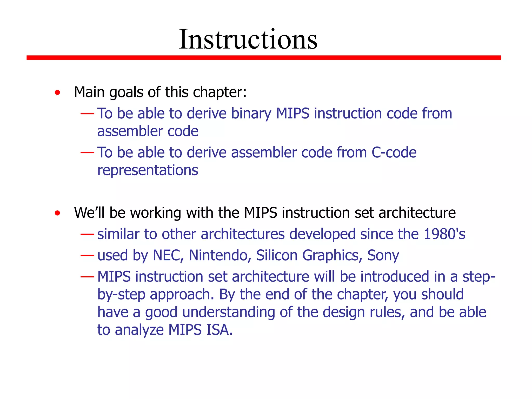
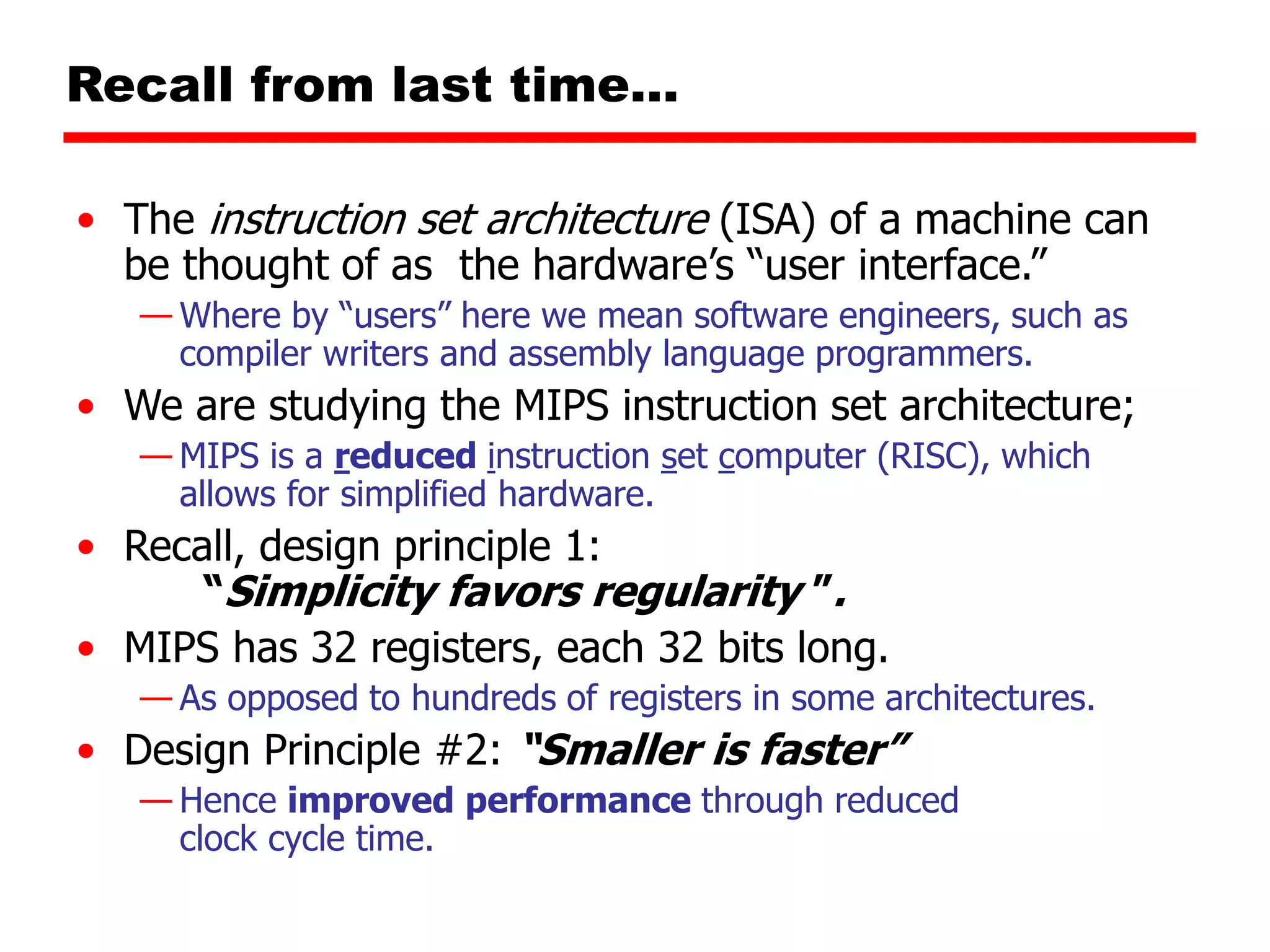
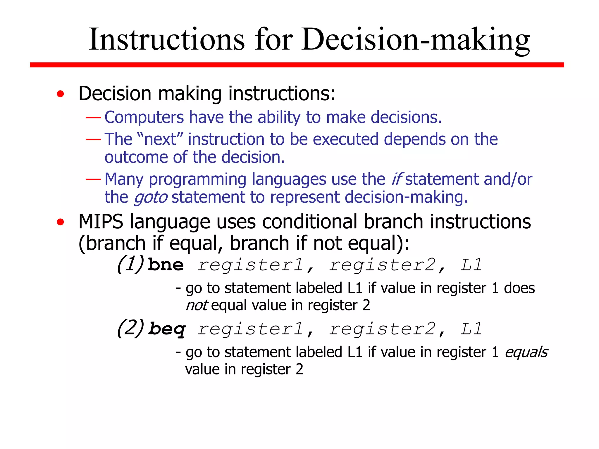
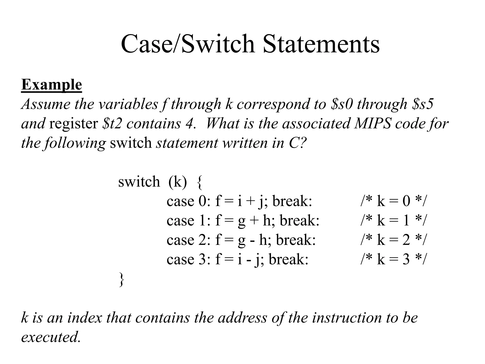
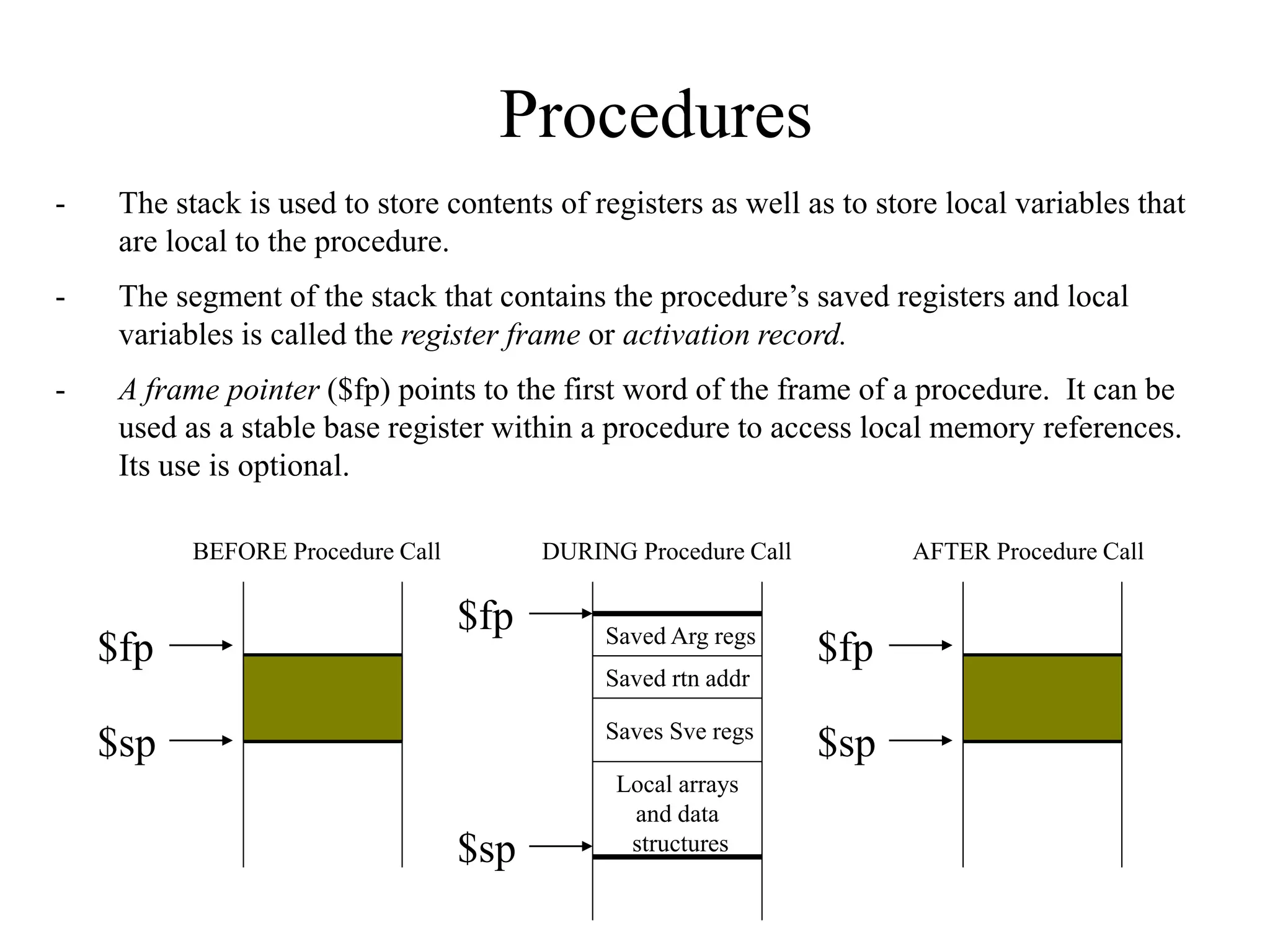
This document discusses the MIPS instruction set architecture and principles of computer architecture. It covers:
- The goals of being able to derive MIPS instruction code from assembler code and assembler code from C code.
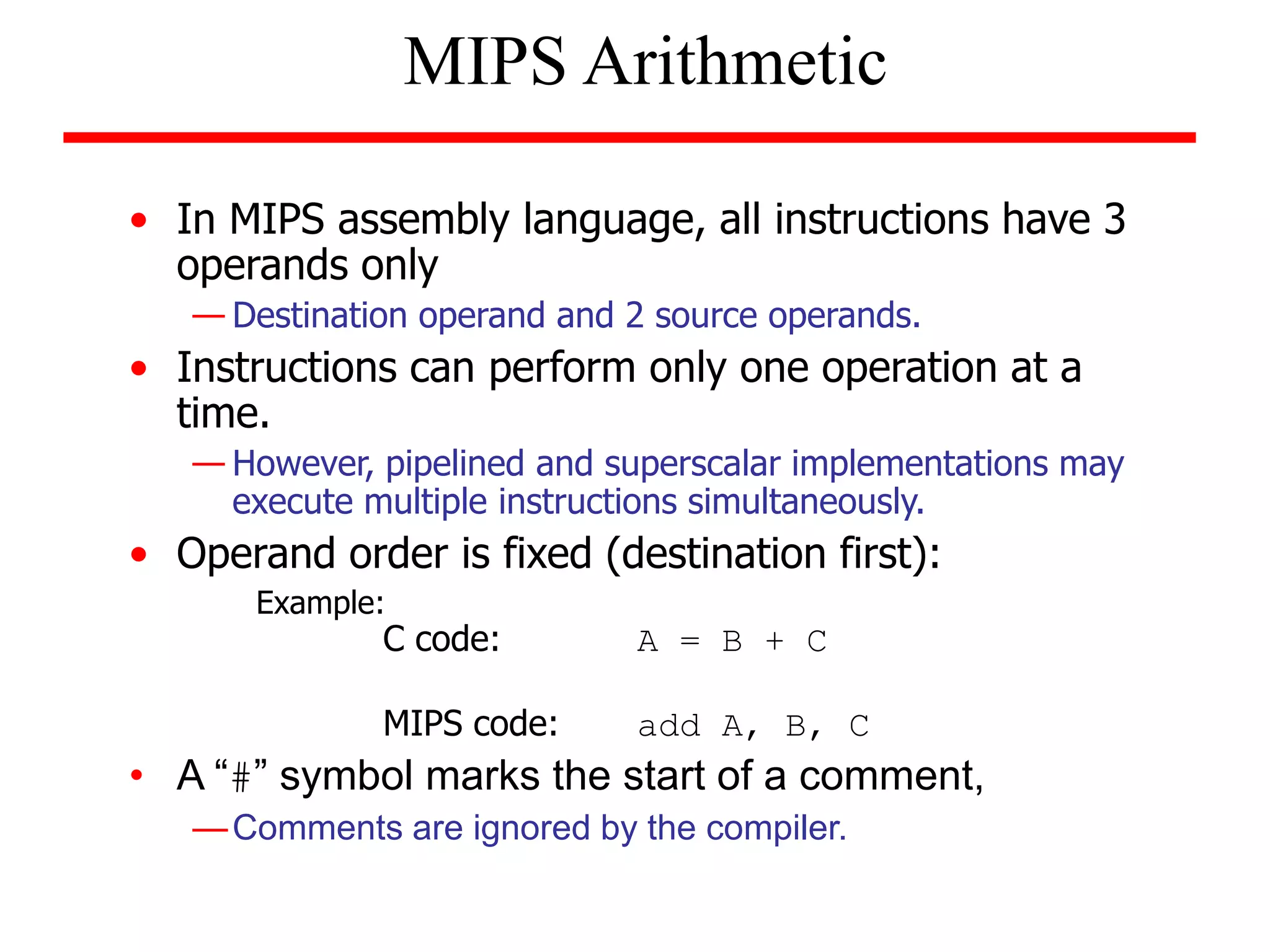
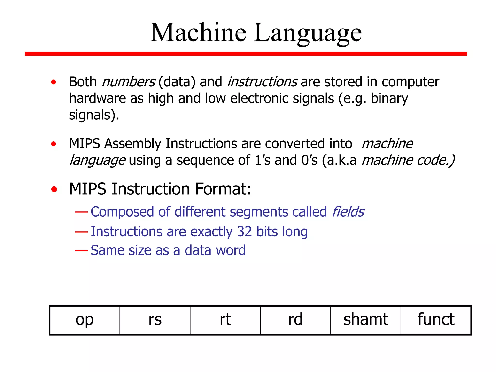
- An introduction to the MIPS instruction set architecture, which has instructions with 3 operands and performs one operation at a time.
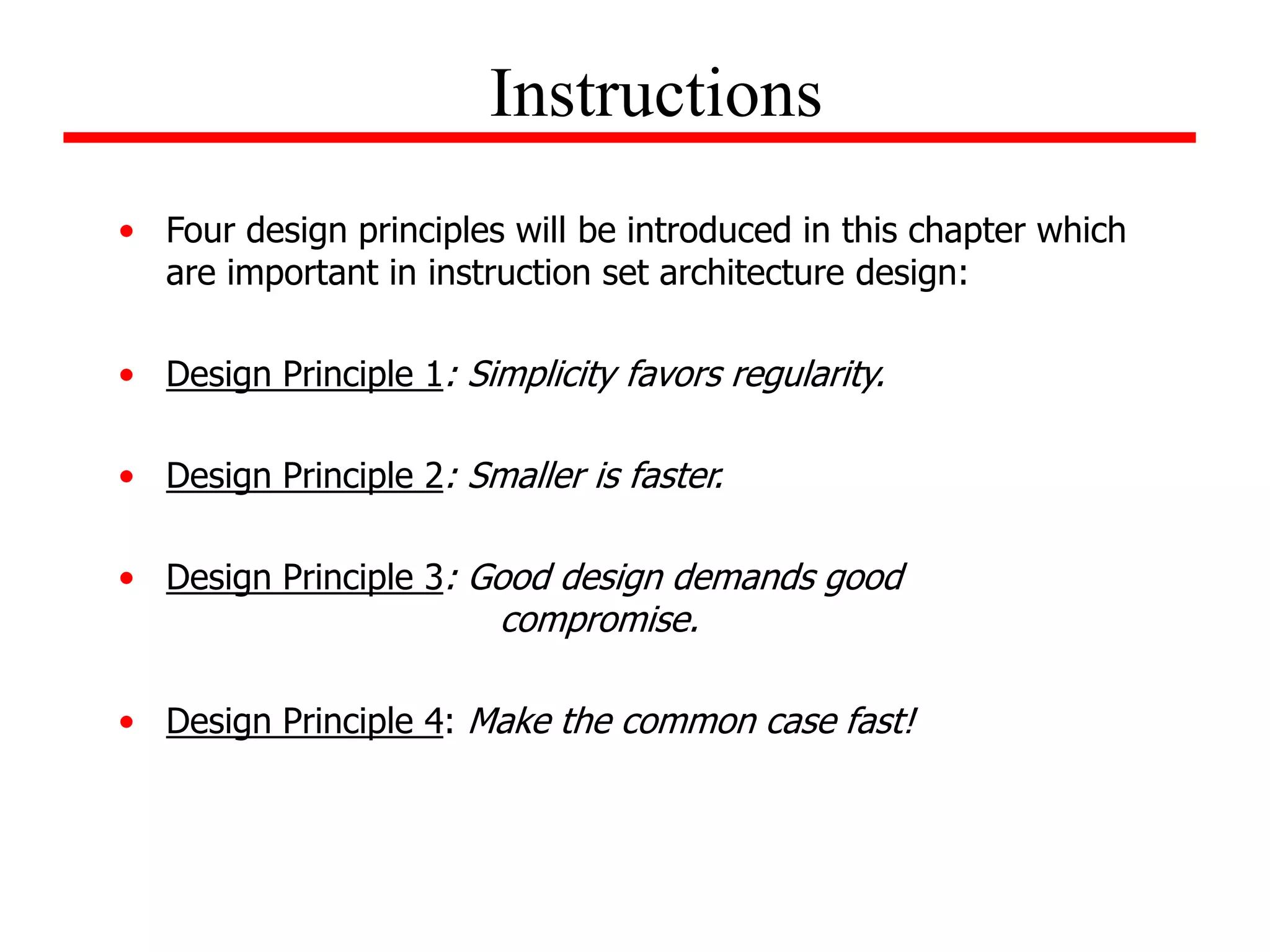
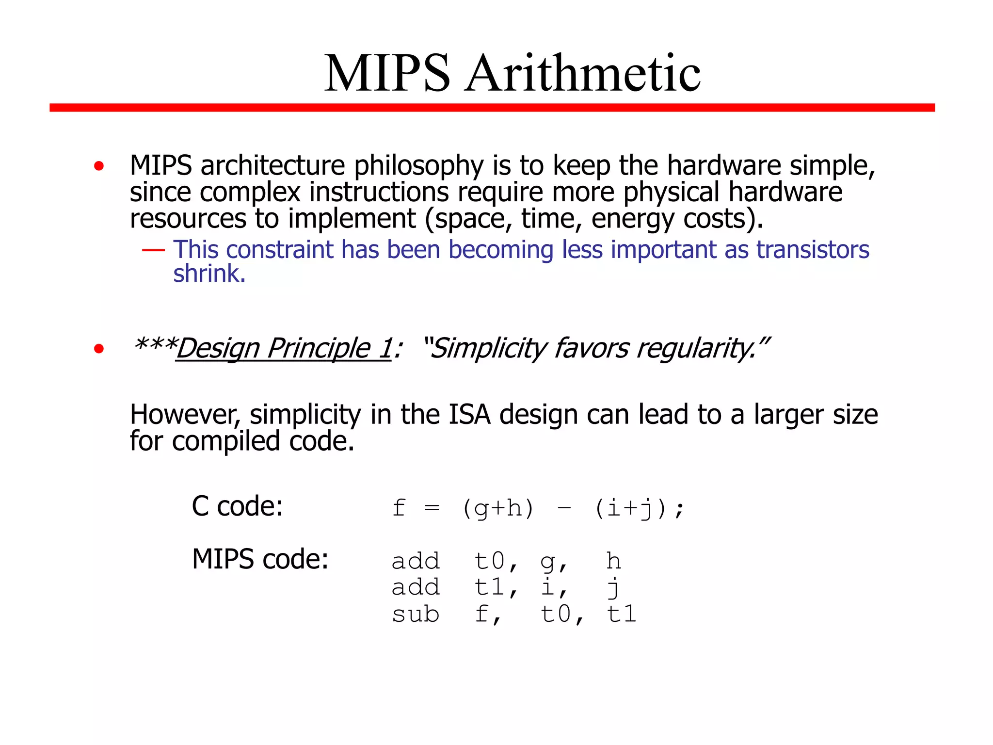
- Four important design principles for instruction set architecture: simplicity favors regularity, smaller is faster, good design demands good compromise, and make the common case fast.
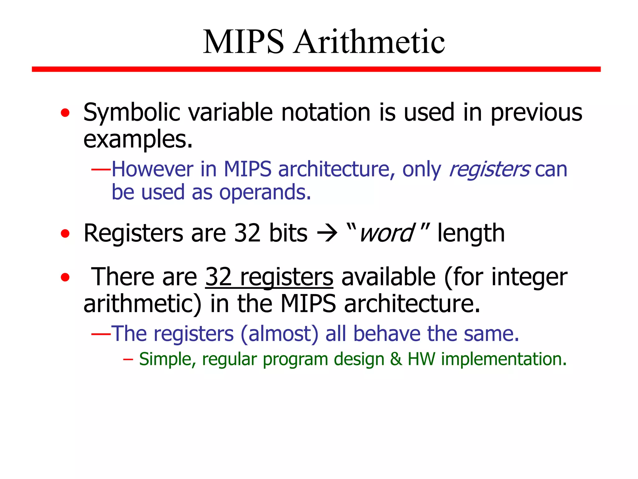
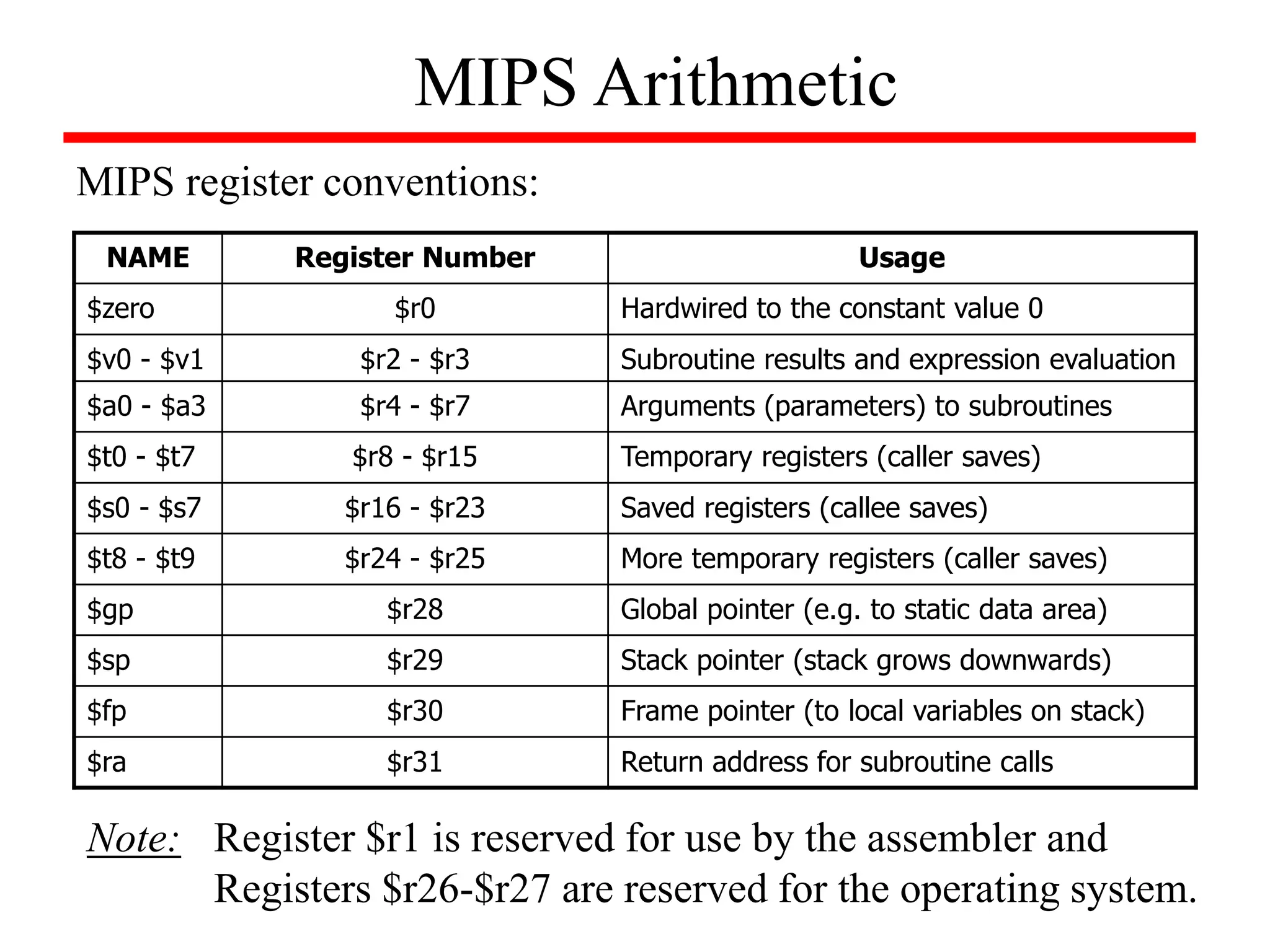
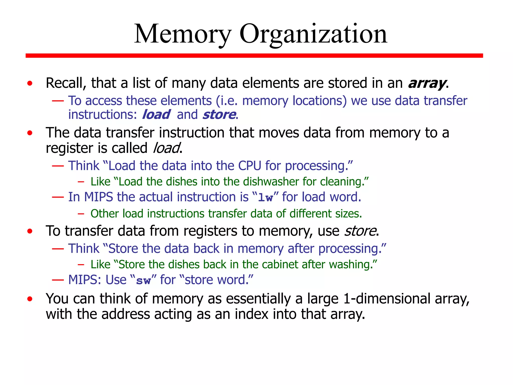
- Details of the MIPS instruction set such as registers, memory organization, and use of load and store instructions to transfer data between registers and memory.
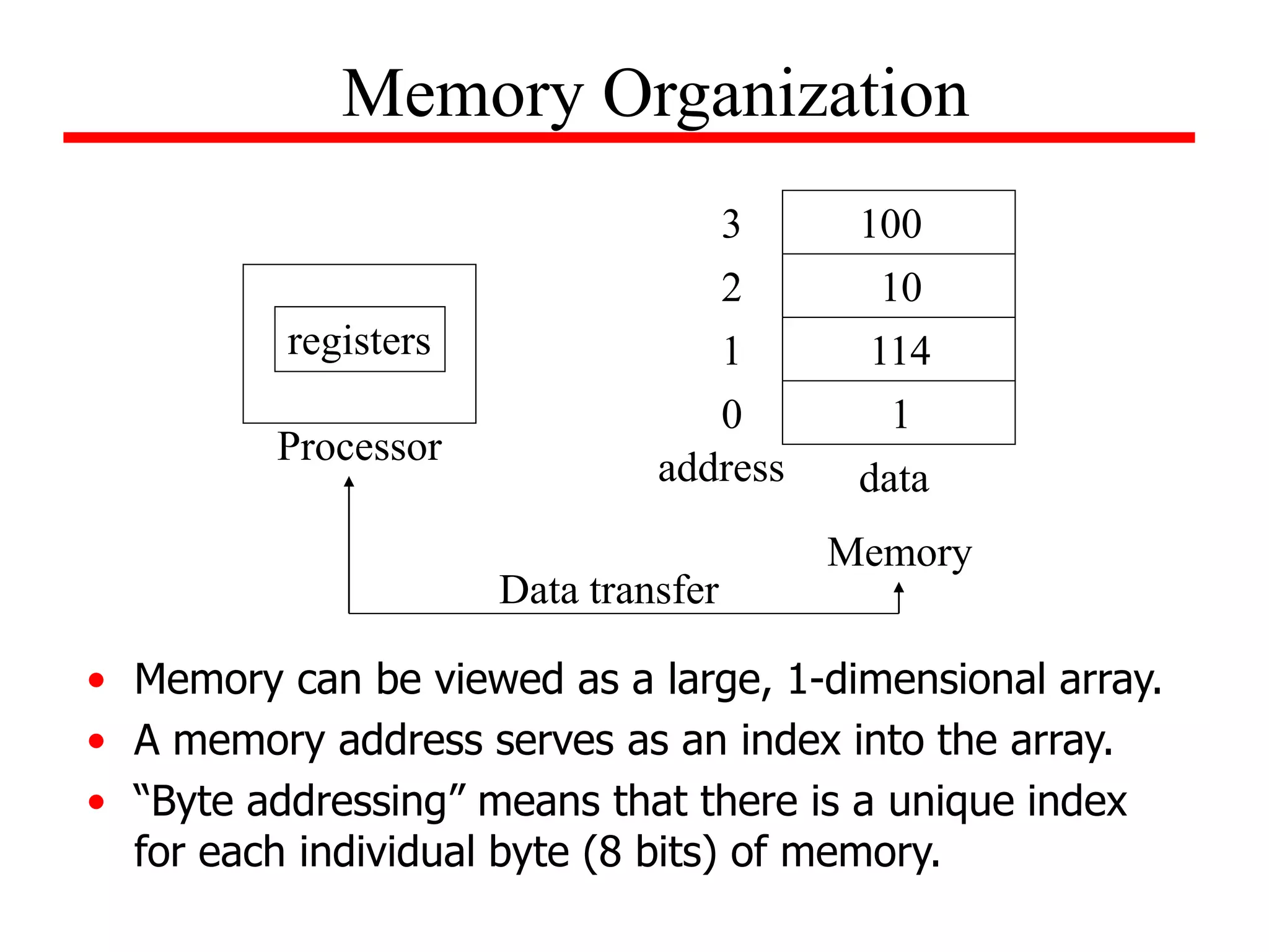
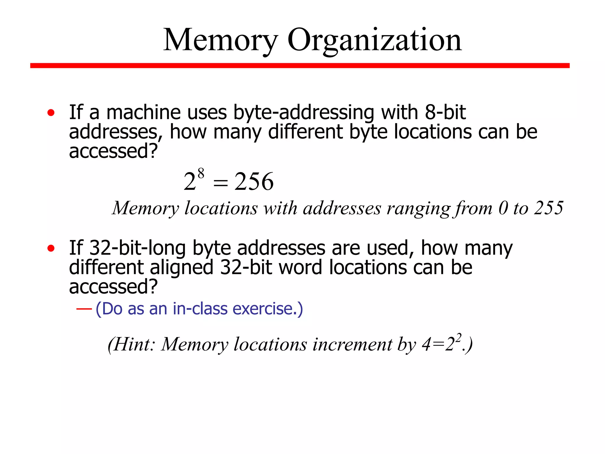
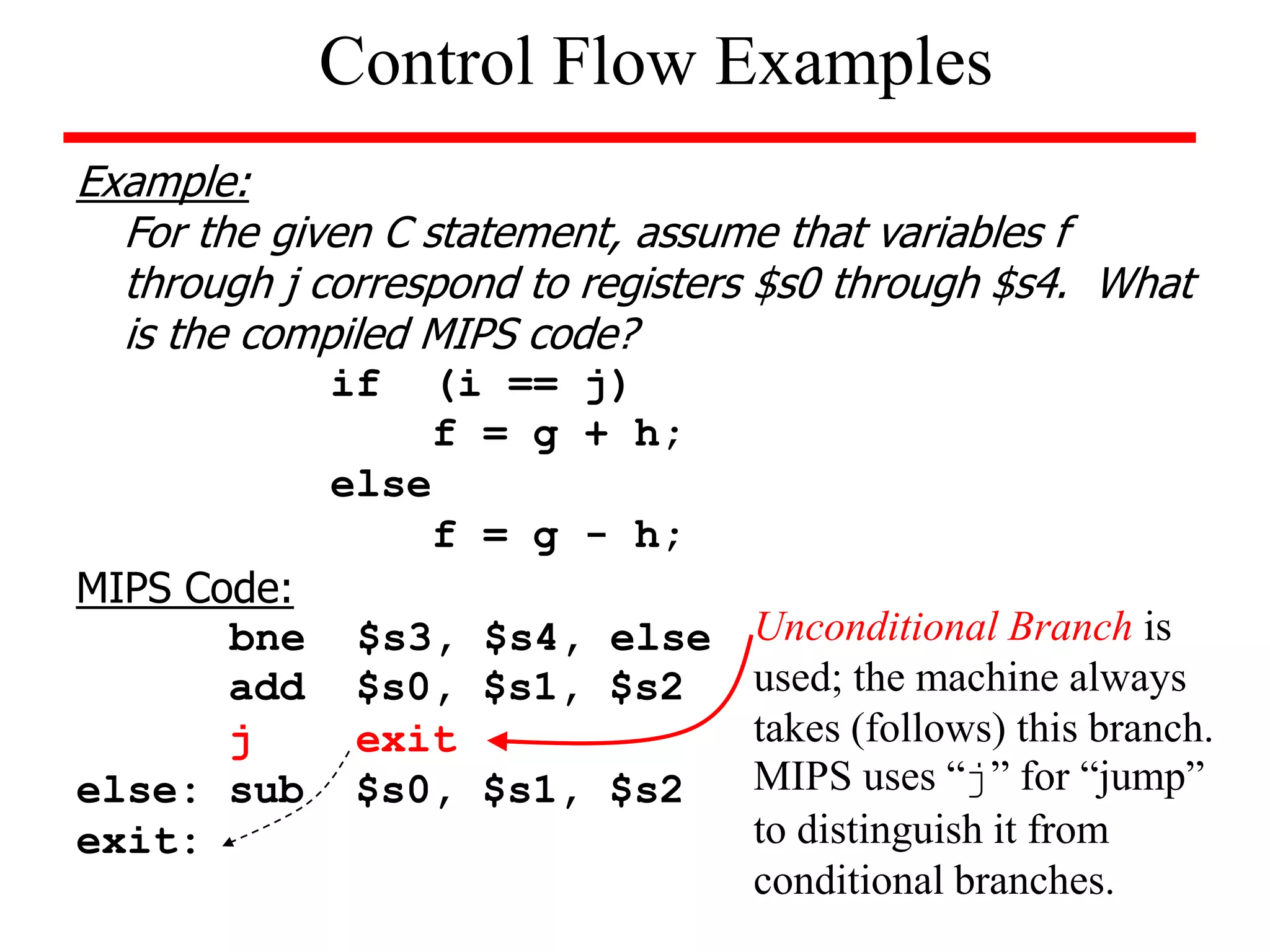
![• Example: The address of the third word in the following array
is 8 and the value of Memory[8]=10.
Memory Organization
1
114
10
100
0
4
8
12
address data
Memory
* This is an example of byte addressing in which the index refers to a byte of
memory. Since words are 32 bits long, the memory address increments by 4
so that words will always start at addresses that are a multiple of 4. This
requirement is known as alignment restriction; it can help to speed up data
transfers.](https://image.slidesharecdn.com/camod05isa-221124160321-e22315c3/75/CA_mod05_ISA-ppt-15-2048.jpg)
![Consider the following example:
Assume that A is an array of 100 words and the compiler has associated registers
$s1 and $s2 with the variables x and y. Also assume that the starting address, or
base address is contained in register $s3. Determine the MIPS instructions
associated with the following C statement:
x = y + A[8]; // adds 8th element in array A to y and stores result in x
Solution:
Before we can perform any arithmetic operations, we must first transfer the data
contained in A[8] to a temporary register.
lw $t0, 32($s3) # $s3 contains the base address of array and
# 32 is the offset address of the 8th element
add $s1, $s2, $t0 # performs addition
Memory Organization](https://image.slidesharecdn.com/camod05isa-221124160321-e22315c3/75/CA_mod05_ISA-ppt-16-2048.jpg)
![Example (using load and store)
Assume that A is an array of 100 words and the compiler has
associated registers $s1 with the variable x. Also assume that
the base address of the array is in register $s2. Determine the
MIPS instructions associated with the following C statement:
A[12] = x + A[8];
Solution:
lw $t0, 32($s2)
add $t0, $s1, $t0
sw $t0, 48($s2)
Memory Organization Example
NOTES:
(1) Store word instruction has destination last as last element.
(2) Remember arithmetic operands are registers only, not memory!](https://image.slidesharecdn.com/camod05isa-221124160321-e22315c3/75/CA_mod05_ISA-ppt-19-2048.jpg)
![Example (using variable array index)
Assume that A is an array of 100 elements and the base is in $s3. Also
assume that the compiler associates g, h, and i with $s1, $s2, and $s4.
Determine the MIPS instructions associated with the following C statement:
g = h + A[i];
Solution:
We need to know that address of the A[i] before we can load it into a
temporary register. Recall, that to access an element in memory we must
multiply it by 4 to account for byte addressing. To accomplish this we perform
the following sequence of operations:
4i First, i + i = 2i then 2i + 2i = 4i
add $t1, $s4, $s4 # temp register holds 2i
add $t1, $t1, $t1 # temp register holds 4i
add $t1, $t1, $s3 # $t1 holds address of A[i]
lw $t0, 0($t1) # loads A[i] into temp register $t0
add $s1, $s2, $t0
Memory Organization Example](https://image.slidesharecdn.com/camod05isa-221124160321-e22315c3/75/CA_mod05_ISA-ppt-20-2048.jpg)
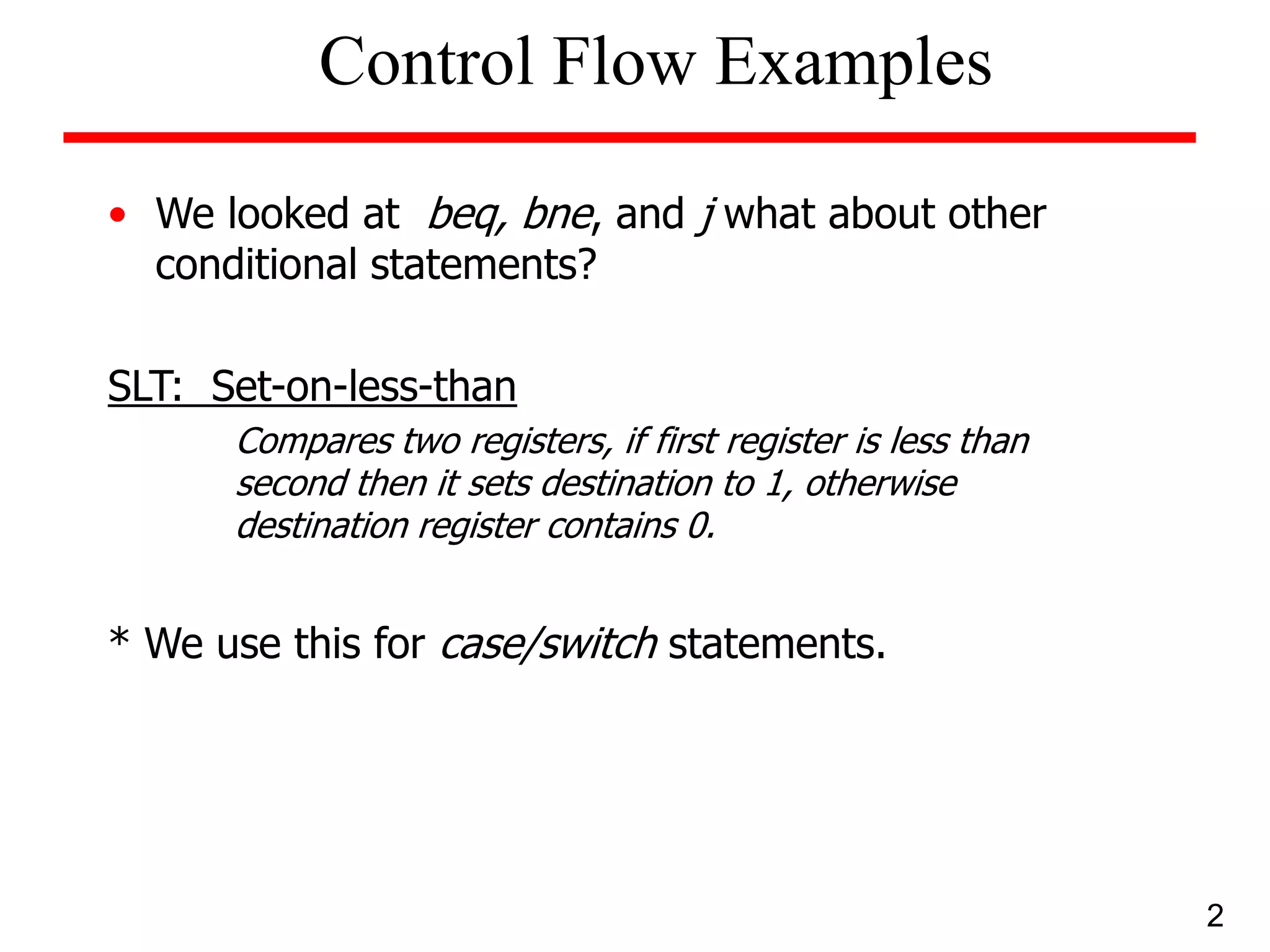
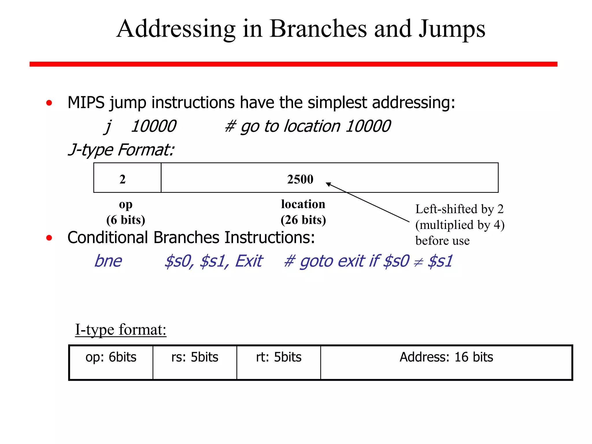
![• MIPS
— loading words but addressing bytes
— arithmetic on registers only
• Instruction Meaning
add $s1, $s2, $s3 $s1 = $s2 + $s3
sub $s1, $s2, $s3 $s1 = $s2 – $s3
lw $s1, 100($s2) $s1 = Memory[$s2+100]
sw $s1, 100($s2) Memory[$s2+100] = $s1
• In programs containing more variables than registers, the compiler
tries to keep the most frequently used variables in registers and the
rest in memory. This process is known as spilling. Why is this
important to system performance?
Recap…](https://image.slidesharecdn.com/camod05isa-221124160321-e22315c3/75/CA_mod05_ISA-ppt-21-2048.jpg)
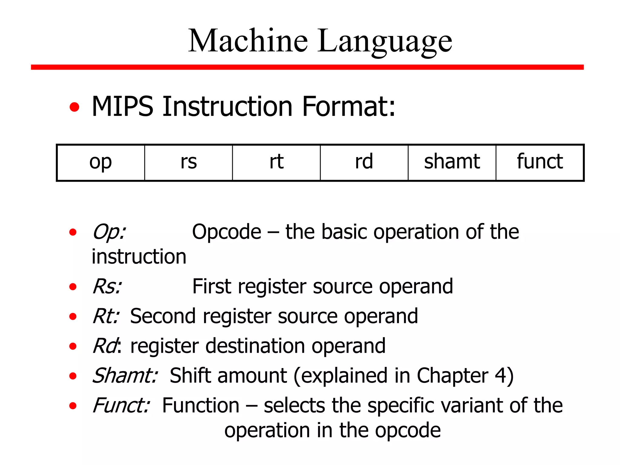

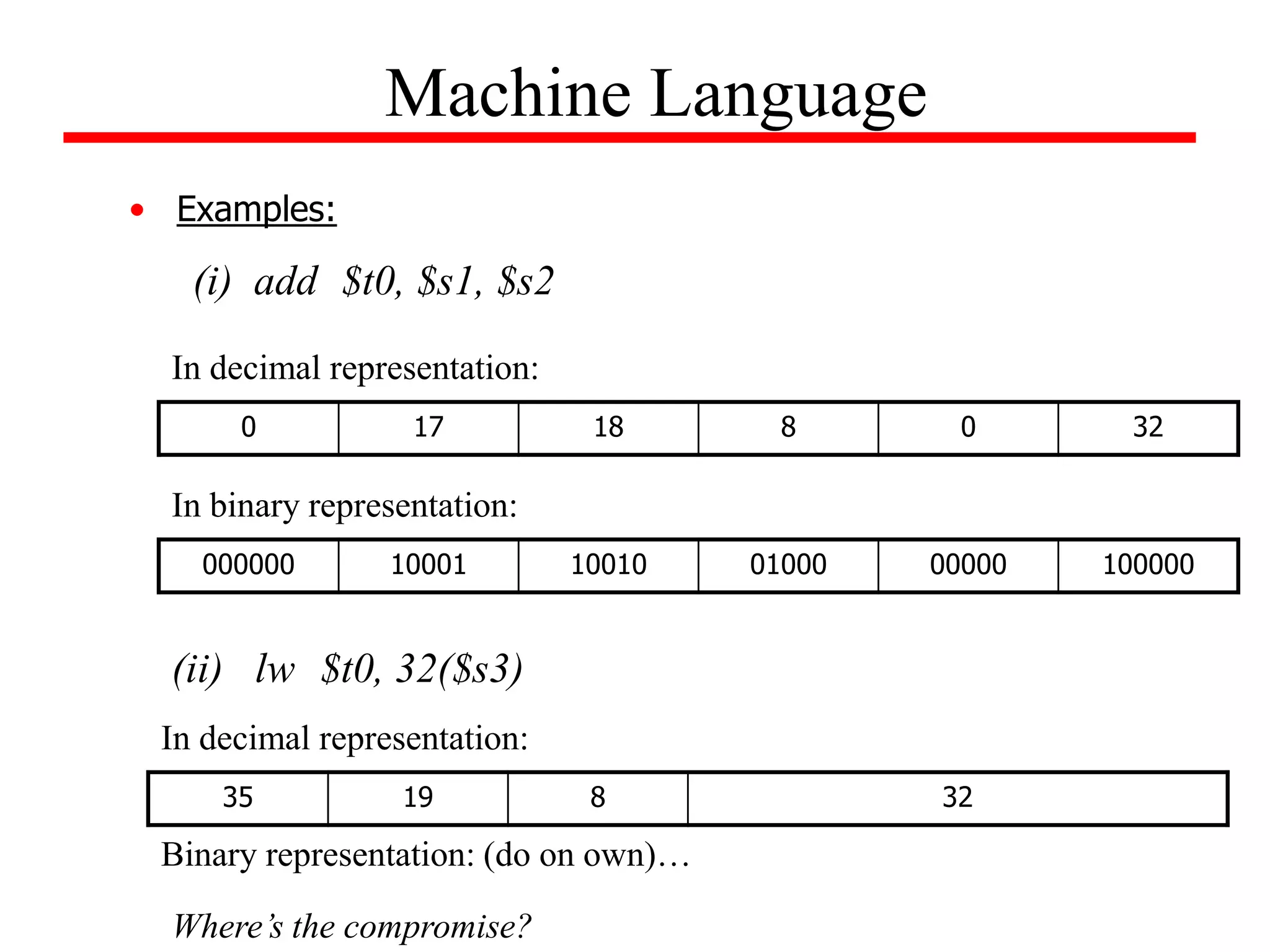
![Machine Language
• Appendix A (on the CD-ROM), pages A-50 through
A-81, gives format for assembly language instructions
in the third edition.
• Example:
For the given C statement, determine its MIPS
assembly code, as well as, its corresponding machine
code. Assume that the base address for A is contained
in $s2.
A[100] = x + A[50];
(do on own)](https://image.slidesharecdn.com/camod05isa-221124160321-e22315c3/75/CA_mod05_ISA-ppt-26-2048.jpg)
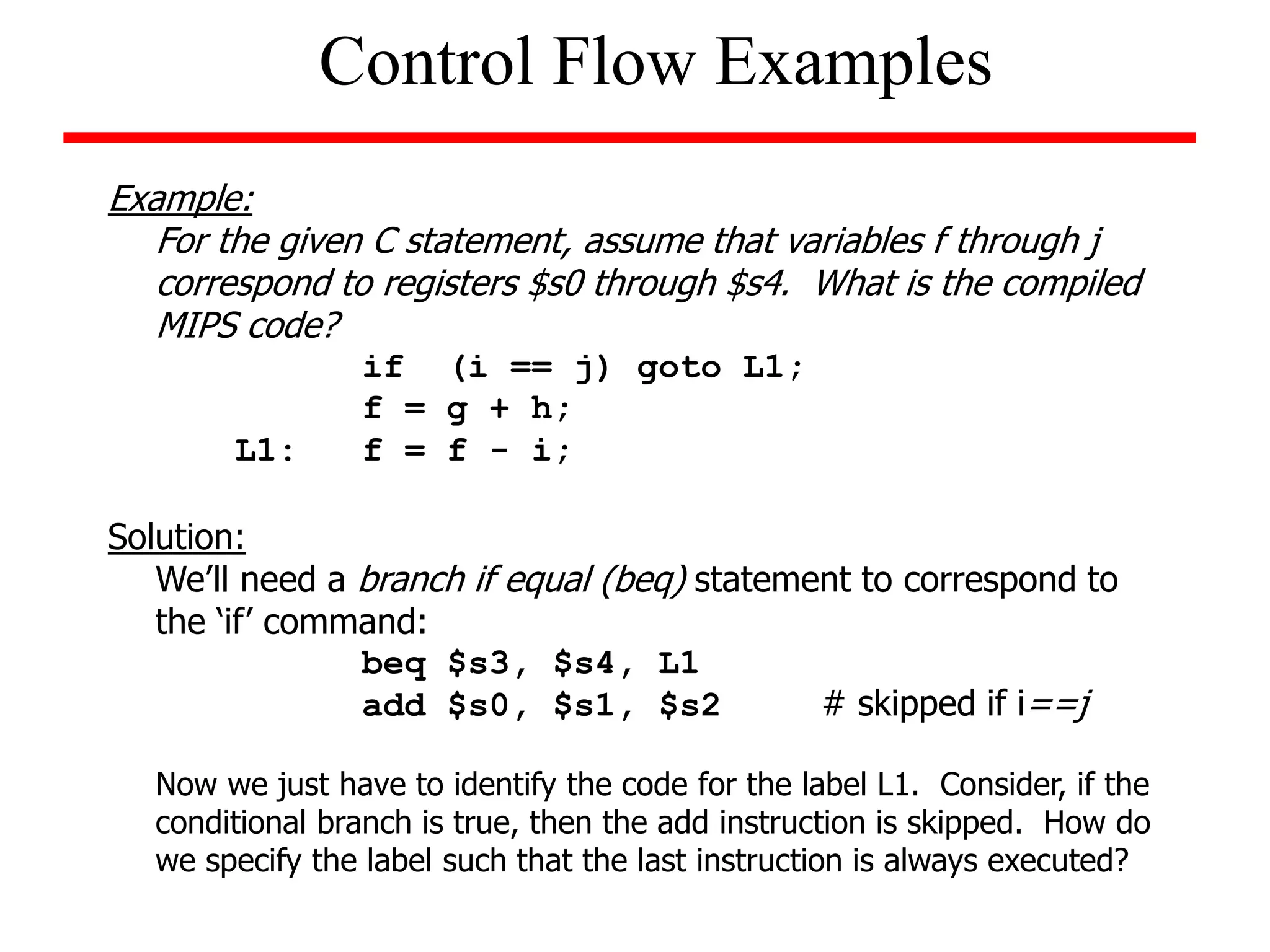
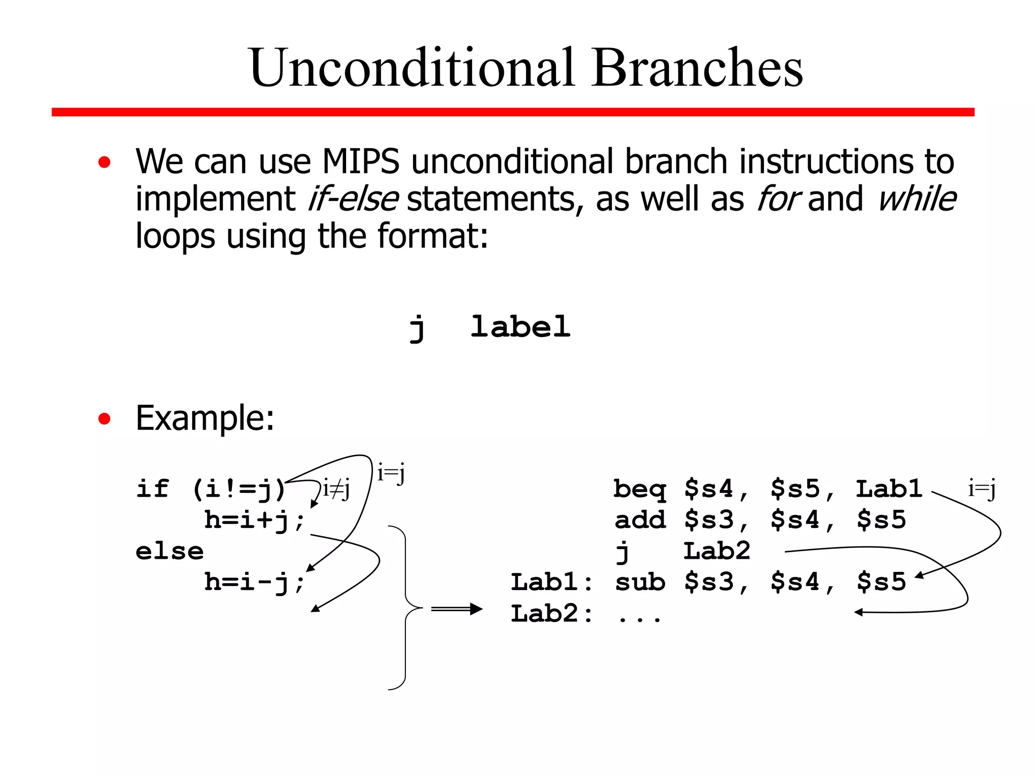
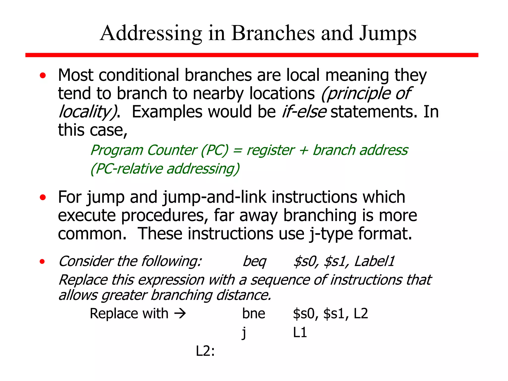
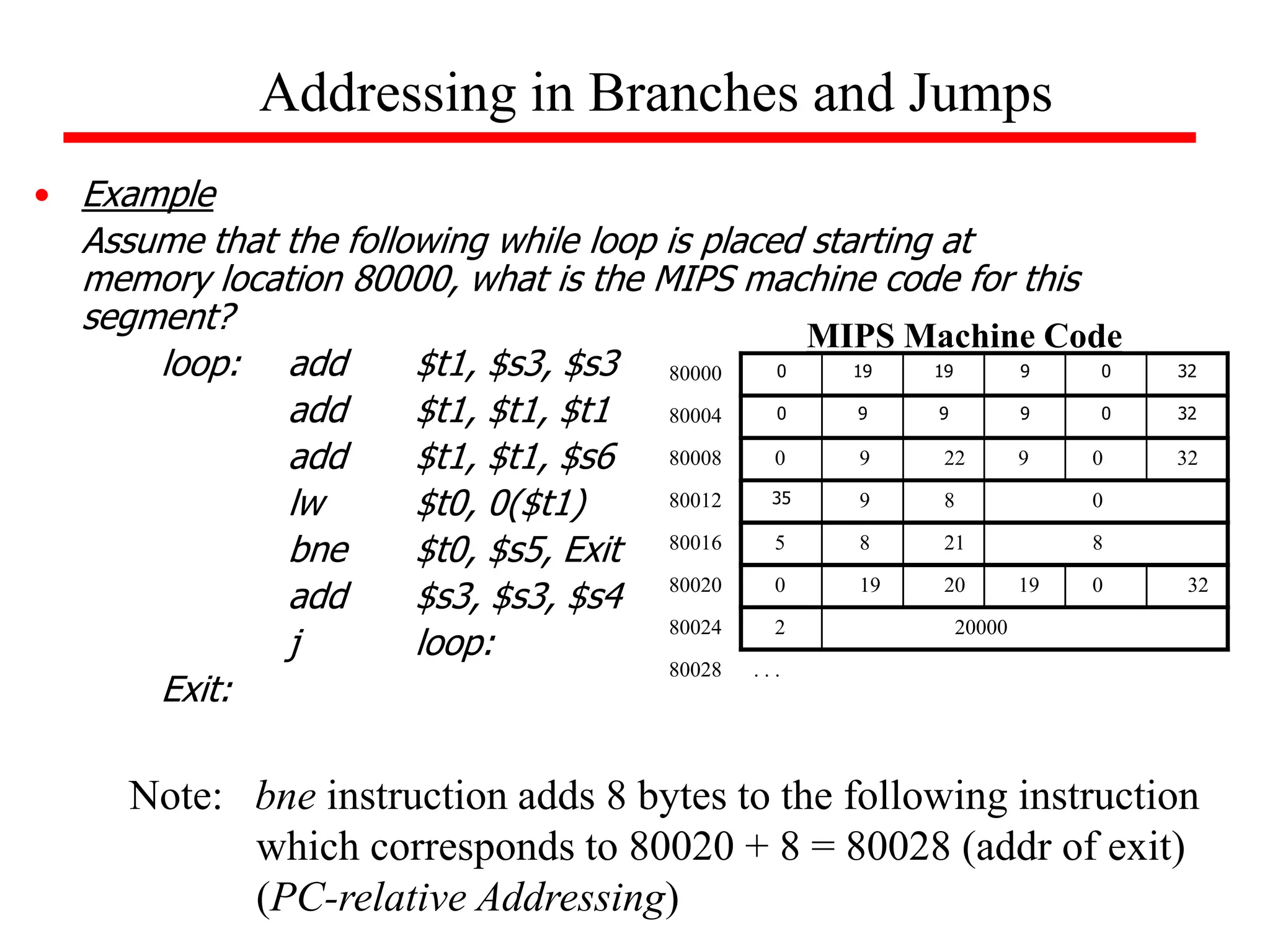
![Example (while loop):
Write the MIPS assembly code for the following C code segment.
Assume that i, j, k correspond to $s3, $s4, $s5 and the base of the
array SAVE is contained in $s6.
while (save [i] = = k)
i = i + j;
Solution
loop: add $t1, $s3, $s3
add $t1, $t1, $t1
add $t1, $t1, $s6
lw $t0, 0($t1)
bne $t0, $s5, exit
add $s3, $s3, $s4
j loop
exit:
Unconditional Branches](https://image.slidesharecdn.com/camod05isa-221124160321-e22315c3/75/CA_mod05_ISA-ppt-33-2048.jpg)
![Example
String Copy Procedure Example:
C Code:
void strcpy(char x[ ], char y[ ])
{
int i;
i = 0;
while ((x[i] = y[i]) != 0) /* copy and test byte */
i = i + 1;
}
strcpy:
sub $sp, $sp, 4
sw $s0, 0($sp)
add $s0,$zero,$zero
L1: add $t1, $a1, $s0
lb $t2, 0($t1)
add $t3, $a0, $s0
sb $t2, 0($t3)
beq $t2, $zero, L2
addi $s0, $s0, 1
j L1
L2: lw $s0, 0($sp)
add $sp, $sp, 4
jr $ra
MIPS Assembly
Assume base addresses for x and y are
found in $a0 and $a1 and i is in $s0.
Note also that x and y are arrays of
characters so there is no need to multiply
by 4 to obtain the address.](https://image.slidesharecdn.com/camod05isa-221124160321-e22315c3/75/CA_mod05_ISA-ppt-51-2048.jpg)
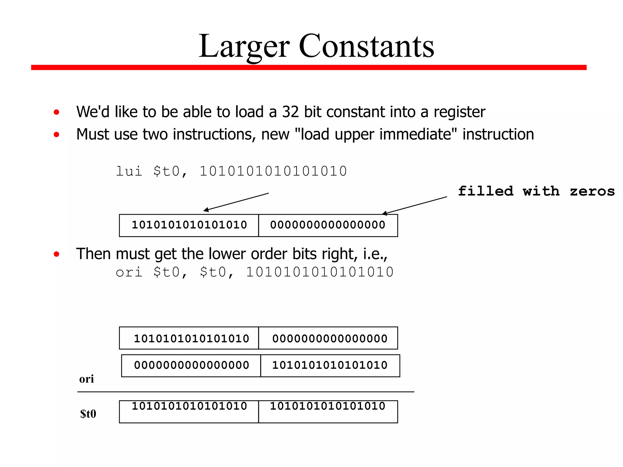
![• Example:
Determine the sequence of MIPS instructions for the following C segment
x[10] = x[11] + c;
Assuming that c is contained in $t0 and that array x has a base address of
First load base address into a register:
Larger Constants
10
)
000
,
000
,
4
(
2
16
10
)
0000
0000
1001
0000
1101
0011
0000
0000
(
)
0900
003
(
)
000
,
000
,
4
(
D
lui $t1, $t1, 0000 0000 0011 1101 # load upper 16 bits
ori $t1, $t1, 0000 1001 0000 0000 # load lower 16 bits using OR imm
lw $t2, 44($t1) # load element x[11] into $t2
add $t2, $t2, $t0 # sum x[11] and c; put result in $t2
sw $t2, 40($t1) # store it back into memory
Solution:
On own: Write MIPS assembly that loads 32-bit word into register $t5:
0000 0000 0011 1101 0000 1001 0000 0000](https://image.slidesharecdn.com/camod05isa-221124160321-e22315c3/75/CA_mod05_ISA-ppt-55-2048.jpg)

![In summary:
MIPS operands
Name Example Comments
$s0-$s7, $t0-$t9, $zero, Fast locations for data. In MIPS, data must be in registers to perform
32 registers $a0-$a3, $v0-$v1, $gp, arithmetic. MIPS register $zero always equals 0. Register $at is
$fp, $sp, $ra, $at reserved for the assembler to handle large constants.
Memory[0], Accessed only by data transfer instructions. MIPS uses byte addresses, so
2
30
memory Memory[4], ..., sequential words differ by 4. Memory holds data structures, such as arrays,
words Memory[4294967292] and spilled registers, such as those saved on procedure calls.
MIPS assembly language
Category Instruction Example Meaning Comments
add add $s1, $s2, $s3 $s1 = $s2 + $s3 Three operands; data in registers
Arithmetic subtract sub $s1, $s2, $s3 $s1 = $s2 - $s3 Three operands; data in registers
add immediate addi $s1, $s2, 100 $s1 = $s2 + 100 Used to add constants
load word lw $s1, 100($s2) $s1 = Memory[$s2 + 100] Word from memory to register
store word sw $s1, 100($s2) Memory[$s2 + 100] = $s1 Word from register to memory
Data transfer load byte lb $s1, 100($s2) $s1 = Memory[$s2 + 100] Byte from memory to register
store byte sb $s1, 100($s2) Memory[$s2 + 100] = $s1 Byte from register to memory
load upper immediate lui $s1, 100
$s1 = 100 * 2
16 Loads constant in upper 16 bits
branch on equal beq $s1, $s2, 25 if ($s1 == $s2) go to
PC + 4 + 100
Equal test; PC-relative branch
Conditional
branch on not equal bne $s1, $s2, 25 if ($s1 != $s2) go to
PC + 4 + 100
Not equal test; PC-relative
branch set on less than slt $s1, $s2, $s3 if ($s2 < $s3) $s1 = 1;
else $s1 = 0
Compare less than; for beq, bne
set less than
immediate
slti $s1, $s2, 100 if ($s2 < 100) $s1 = 1;
else $s1 = 0
Compare less than constant
jump j 2500 go to 10000 Jump to target address
Uncondi- jump register jr $ra go to $ra For switch, procedure return
tional jump jump and link jal 2500 $ra = PC + 4; go to 10000 For procedure call](https://image.slidesharecdn.com/camod05isa-221124160321-e22315c3/75/CA_mod05_ISA-ppt-61-2048.jpg)
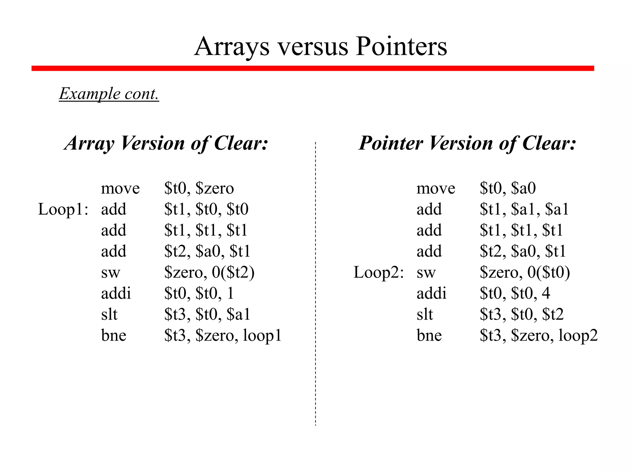
![Arrays versus Pointers
Example
What is the assembly language for the following C procedures:
clear1(int array[ ],int size)
{
int i;
for (i=0; i<size; i=i+1)
array[i] = 0;
}
clear2(int *array,int size)
{
int *p;
for (p=&array[0]; p<&array[size]; p=p+1)
*p = 0;
}
Array Version
Pointer Version](https://image.slidesharecdn.com/camod05isa-221124160321-e22315c3/75/CA_mod05_ISA-ppt-65-2048.jpg)


![[BDD 2025 - Artificial Intelligence] AI for the Underdogs: Innovation for Sma...](https://cdn.slidesharecdn.com/ss_thumbnails/ai-aifortheunderdogsinnovationforsmallbusinesses-251124030839-72a599a4-thumbnail.jpg?width=640&height=640&fit=bounds)


![[BDD 2025 - Full-Stack Development] Agentic AI Architecture: Redefining Syste...](https://cdn.slidesharecdn.com/ss_thumbnails/fs-agenticaiarchitectureredefiningsystemcommunication-251124030838-e6c70cc2-thumbnail.jpg?width=640&height=640&fit=bounds)


![[BDD 2025 - Mobile Development] Crafting Immersive UI with E2E and AGSL Shade...](https://cdn.slidesharecdn.com/ss_thumbnails/md-craftingimmersiveuiwithe2eandagslshaderveronicaputrianggraini-251124030840-0c677f44-thumbnail.jpg?width=640&height=640&fit=bounds)
![[BDD 2025 - Mobile Development] Mobile Engineer and Software Engineer: Are we...](https://cdn.slidesharecdn.com/ss_thumbnails/md-mobileengineerandsoftwareengineerarewestillrelevantsidiqpermana-251127010650-55224ef1-thumbnail.jpg?width=640&height=640&fit=bounds)
