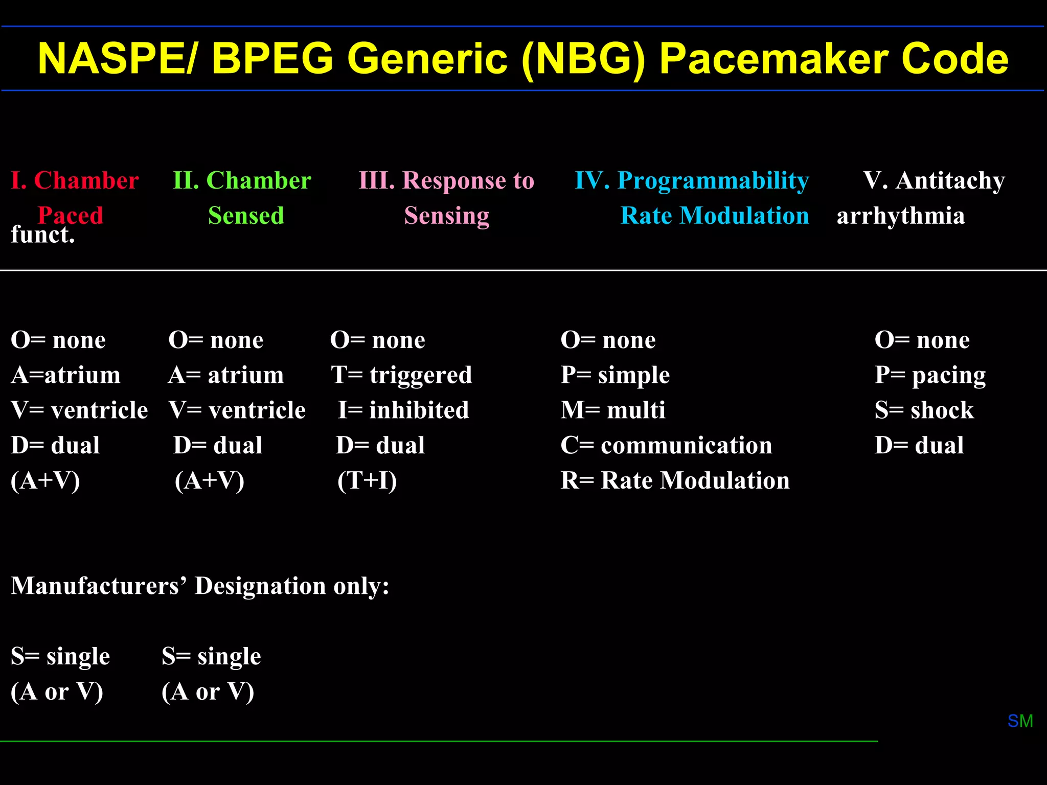
1) Unipolar and bipolar pacing configurations determine the size of the electrical field for sensing and stimulation. Bipolar pacing has a smaller field to reduce muscle stimulation.
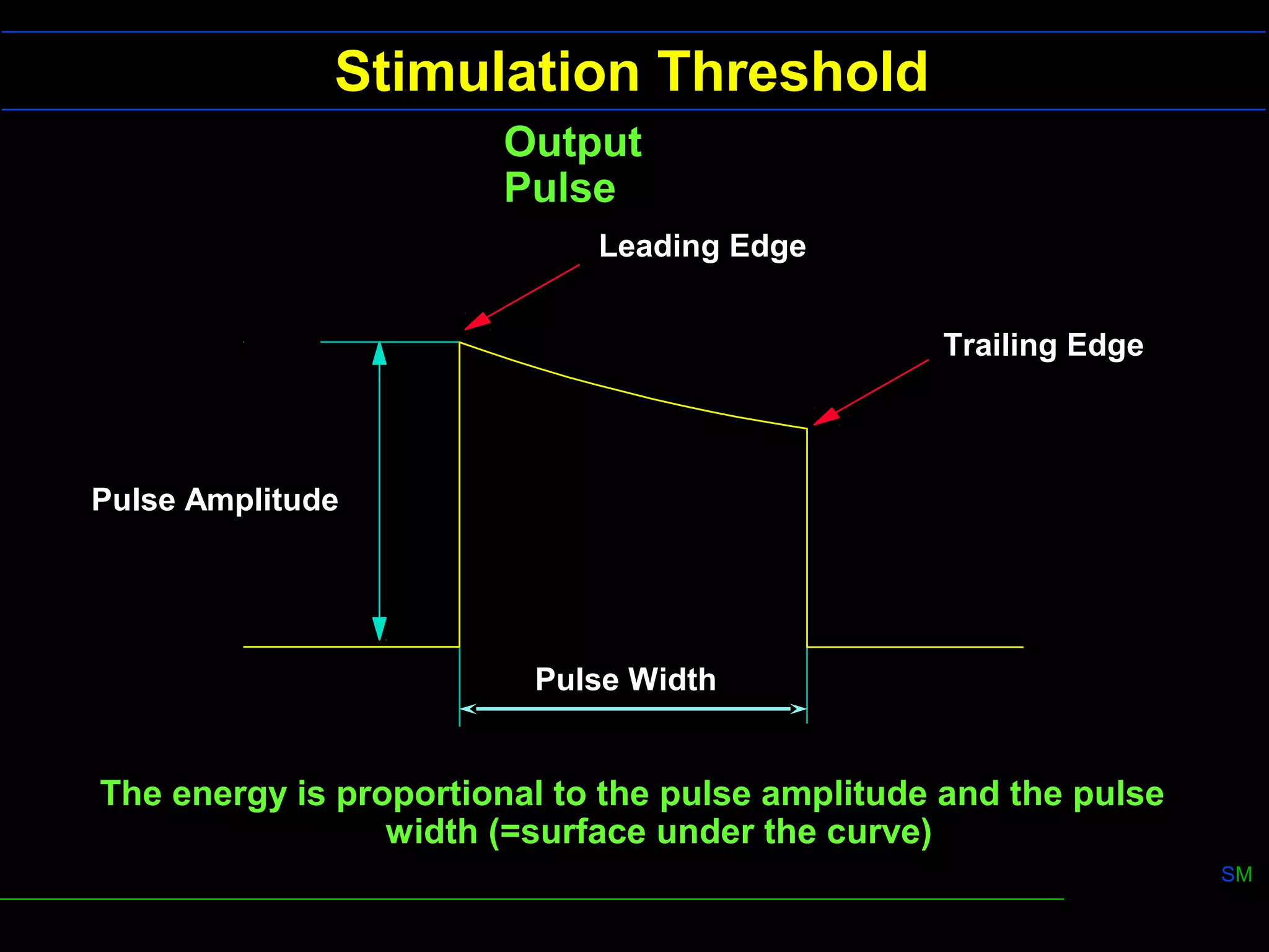
2) Pacemaker output is determined by pulse amplitude and width. Increasing either increases energy delivered. Strength-duration curves show relationships between pulse parameters and stimulation threshold.
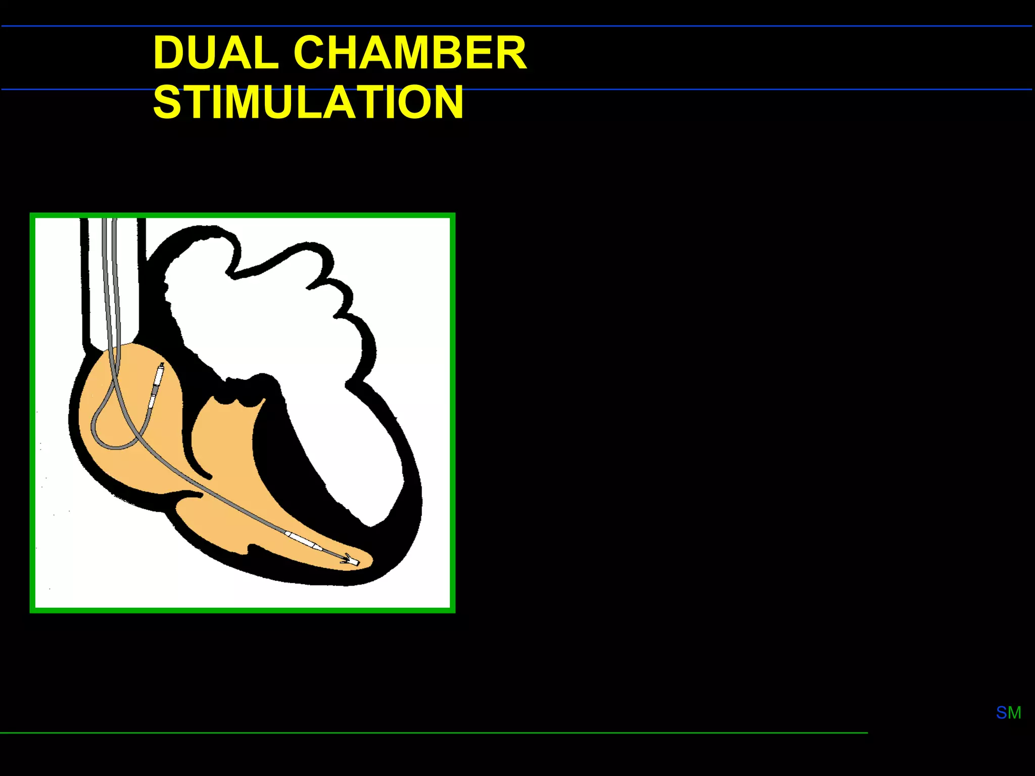
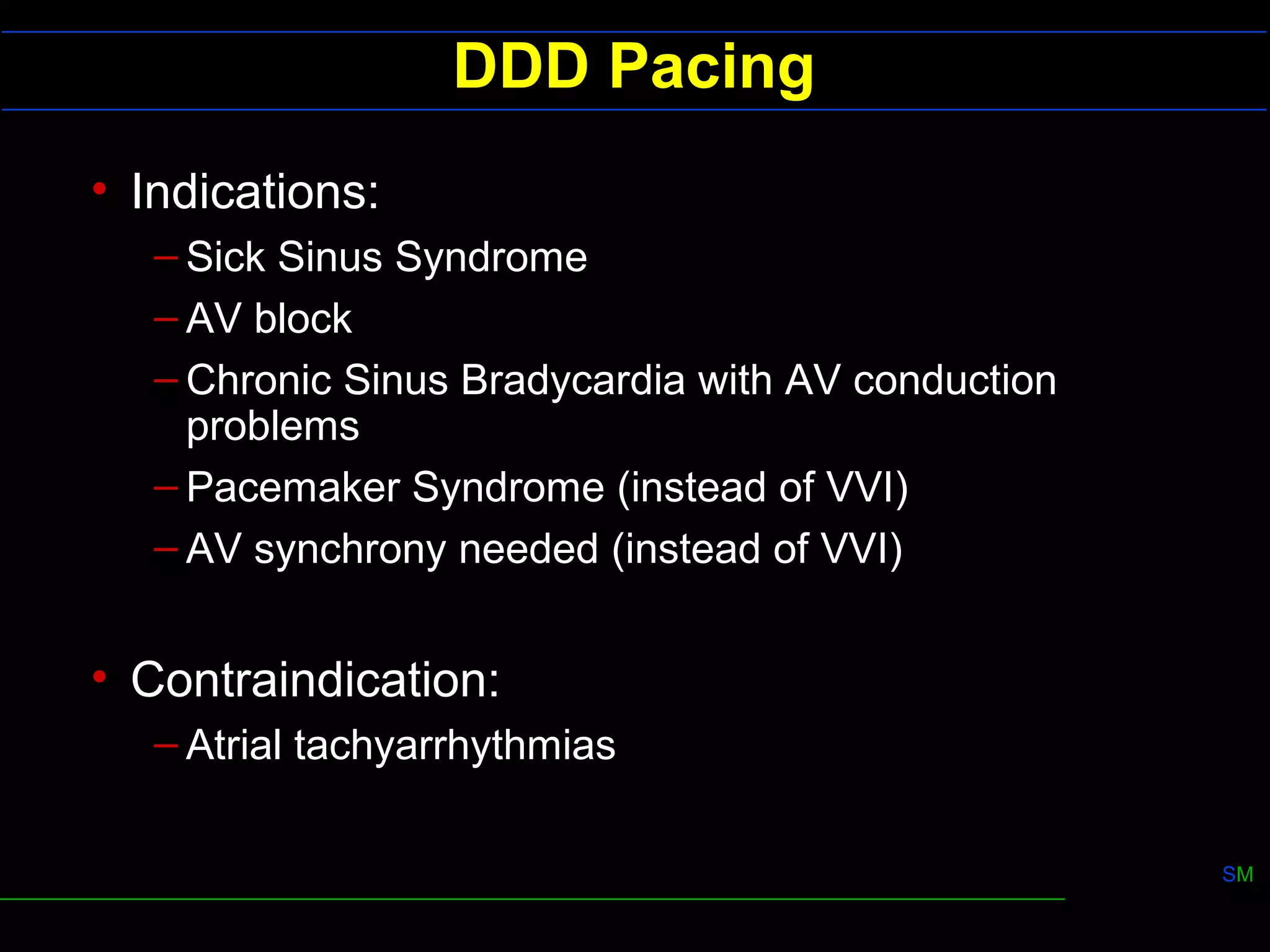
3) Dual chamber pacing (DDD mode) provides atrioventricular synchrony for better cardiac output than single chamber pacing. It uses refractory periods and programmable delays to control ventricular pacing in response to atrial signals.