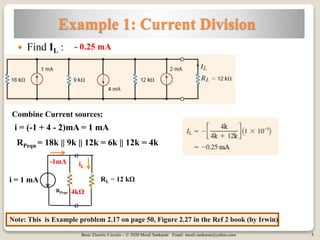
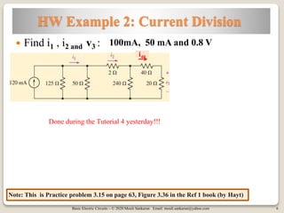
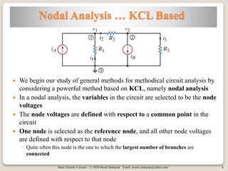
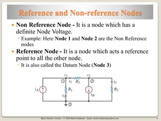
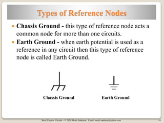
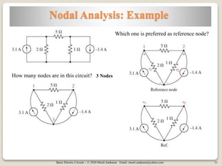
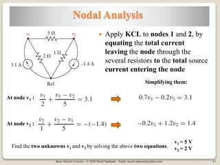
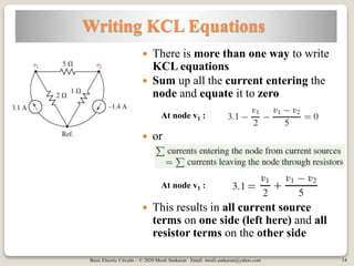
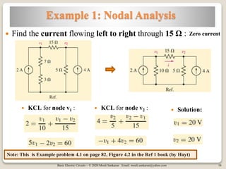
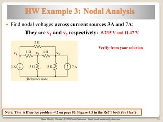
Basic Electric Circuits – © 2020 Mouli Sankaran Email: mouli.sankaran@yahoo.com
Basic Electric Circuits – © 2020 Mouli Sankaran Email: mouli.sankaran@yahoo.com 2
Session 8A: Focus
 Current Division
◦ Examples
 Basic Nodal Analysis
◦ Nodes and reference nodes
 Nodal Analysis
◦ Example
◦ Solve using Nodal analysis
 Writing KCL Equations
 Example Problems
Basic Electric Circuits – © 2020 Mouli Sankaran Email: mouli.sankaran@yahoo.com
Resistors in Parallel – Current Division
Basic Electric Circuits – © 2020 Mouli Sankaran Email: mouli.sankaran@yahoo.com 4
Resistors in Parallel: Current Division
 The dual of voltage division is current
division.
 The current flowing through R2 is:
 Or
 For a parallel combination of N resistors, the current through Rk
Basic Electric Circuits – © 2020 Mouli Sankaran Email: mouli.sankaran@yahoo.com 5
Example 1: Current Division
 Find IL :
Note: This is Example problem 2.17 on page 50, Figure 2.27 in the Ref 2 book (by Irwin)
- 0.25 mA
RPequ = 18k || 9k || 12k = 6k || 12k = 4k
Combine Current sources:
i = (-1 + 4 - 2)mA = 1 mA
i = 1 mA RL = 12 kΩ
-1mA
RPequ
iL
4kΩ
o
o
Basic Electric Circuits – © 2020 Mouli Sankaran Email: mouli.sankaran@yahoo.com 6
HW Example 2: Current Division
 Find i1 , i2 and v3 :
Note: This is Practice problem 3.15 on page 63, Figure 3.36 in the Ref 1 book (by Hayt)
i40
100mA, 50 mA and 0.8 V
Done during the Tutorial 4 yesterday!!!
Basic Electric Circuits – © 2020 Mouli Sankaran Email: mouli.sankaran@yahoo.com
Nodal Analysis
Basic Electric Circuits – © 2020 Mouli Sankaran Email: mouli.sankaran@yahoo.com 8
Nodal Analysis … KCL Based
 We begin our study of general methods for methodical circuit analysis by
considering a powerful method based on KCL, namely nodal analysis
 In a nodal analysis, the variables in the circuit are selected to be the node
voltages
 The node voltages are defined with respect to a common point in the
circuit
 One node is selected as the reference node, and all other node voltages
are defined with respect to that node
◦ Quite often this node is the one to which the largest number of branches are
connected
Basic Electric Circuits – © 2020 Mouli Sankaran Email: mouli.sankaran@yahoo.com 9
Reference and Non-reference Nodes
 Non Reference Node - It is a node which has a
definite Node Voltage.
◦ Example: Here Node 1 and Node 2 are the Non Reference
nodes
 Reference Node - It is a node which acts a reference
point to all the other node.
◦ It is also called the Datum Node (Node 3)
Basic Electric Circuits – © 2020 Mouli Sankaran Email: mouli.sankaran@yahoo.com 10
Types of Reference Nodes
 Chassis Ground - this type of reference node acts a
common node for more than one circuits.
 Earth Ground - when earth potential is used as a
reference in any circuit then this type of reference
node is called Earth Ground.
Chassis Ground Earth Ground
Basic Electric Circuits – © 2020 Mouli Sankaran Email: mouli.sankaran@yahoo.com 11
Nodal Analysis: Example
How many nodes are in this circuit?
Which one is preferred as reference node?
3 Nodes
Basic Electric Circuits – © 2020 Mouli Sankaran Email: mouli.sankaran@yahoo.com 12
Nodal Voltages
 The voltage of node 1 relative to the reference node is named
v1, and v2 is defined as the voltage of node 2 with respect to
the reference node.
 These two voltages are all we need, as the voltage between
any other pair of nodes may be found in terms of them
 For example, the voltage of node 1 with respect to node 2 is
v1 − v2.
◦ Similarly, voltage of node 2 with respect to node 1 is v2 − v1
Basic Electric Circuits – © 2020 Mouli Sankaran Email: mouli.sankaran@yahoo.com 13
Nodal Analysis
 Apply KCL to nodes 1 and 2, by
equating the total current
leaving the node through the
several resistors to the total source
current entering the node
At node v1 :
At node v2 :
Simplifying them:
Find the two unknowns v1 and v2 by solving the above two equations.
v1 = 5 V
v2 = 2 V
Basic Electric Circuits – © 2020 Mouli Sankaran Email: mouli.sankaran@yahoo.com 14
Writing KCL Equations
 There is more than one way to write
KCL equations
 Sum up all the current entering the
node and equate it to zero
 or
 This results in all current source
terms on one side (left here) and all
resistor terms on the other side
At node v1 :
At node v1 :
Basic Electric Circuits – © 2020 Mouli Sankaran Email: mouli.sankaran@yahoo.com
Nodal Analysis: Examples
Basic Electric Circuits – © 2020 Mouli Sankaran Email: mouli.sankaran@yahoo.com 16
Example 1: Nodal Analysis
 KCL for node v1 :
 Find the current flowing left to right through 15 Ω :
 KCL for node v2 :  Solution:
Zero current
Note: This is Example problem 4.1 on page 82, Figure 4.2 in the Ref 1 book (by Hayt)
Basic Electric Circuits – © 2020 Mouli Sankaran Email: mouli.sankaran@yahoo.com 17
Example 2: Nodal Analysis
 KCL for node v1 :
 Find nodal voltages v1, v2 and v3 :
 KCL for node v2 :  KCL for node v3 :
 By solving these equations:
Note: This is Example problem 4.2 on page 83, Figure 4.4 in the Ref 1 book (by Hayt)
Basic Electric Circuits – © 2020 Mouli Sankaran Email: mouli.sankaran@yahoo.com 18
HW Example 3: Nodal Analysis
 Find nodal voltages across current sources 3A and 7A:
They are v1 and v3 respectively:
v3v2v1
5.235 V and 11.47 V
Note: This is Practice problem 4.2 on page 86, Figure 4.5 in the Ref 1 book (by Hayt)
Verify from your solution
Basic Electric Circuits – © 2020 Mouli Sankaran Email: mouli.sankaran@yahoo.com 19
Session 8A: Summary
 Current Division
◦ Examples
 Basic Nodal Analysis
◦ Nodes and reference nodes
 Nodal Analysis
◦ Example
◦ Solve using Nodal analysis
 Writing KCL Equations
 Example and Home work Problems
Basic Electric Circuits – © 2020 Mouli Sankaran Email: mouli.sankaran@yahoo.com 20
References
Ref 1 Ref 2

Basic Electric Circuits Session 8A

  • 1.
    Basic Electric Circuits– © 2020 Mouli Sankaran Email: mouli.sankaran@yahoo.com
  • 2.
    Basic Electric Circuits– © 2020 Mouli Sankaran Email: mouli.sankaran@yahoo.com 2 Session 8A: Focus  Current Division ◦ Examples  Basic Nodal Analysis ◦ Nodes and reference nodes  Nodal Analysis ◦ Example ◦ Solve using Nodal analysis  Writing KCL Equations  Example Problems
  • 3.
    Basic Electric Circuits– © 2020 Mouli Sankaran Email: mouli.sankaran@yahoo.com Resistors in Parallel – Current Division
  • 4.
    Basic Electric Circuits– © 2020 Mouli Sankaran Email: mouli.sankaran@yahoo.com 4 Resistors in Parallel: Current Division  The dual of voltage division is current division.  The current flowing through R2 is:  Or  For a parallel combination of N resistors, the current through Rk
  • 5.
    Basic Electric Circuits– © 2020 Mouli Sankaran Email: mouli.sankaran@yahoo.com 5 Example 1: Current Division  Find IL : Note: This is Example problem 2.17 on page 50, Figure 2.27 in the Ref 2 book (by Irwin) - 0.25 mA RPequ = 18k || 9k || 12k = 6k || 12k = 4k Combine Current sources: i = (-1 + 4 - 2)mA = 1 mA i = 1 mA RL = 12 kΩ -1mA RPequ iL 4kΩ o o
  • 6.
    Basic Electric Circuits– © 2020 Mouli Sankaran Email: mouli.sankaran@yahoo.com 6 HW Example 2: Current Division  Find i1 , i2 and v3 : Note: This is Practice problem 3.15 on page 63, Figure 3.36 in the Ref 1 book (by Hayt) i40 100mA, 50 mA and 0.8 V Done during the Tutorial 4 yesterday!!!
  • 7.
    Basic Electric Circuits– © 2020 Mouli Sankaran Email: mouli.sankaran@yahoo.com Nodal Analysis
  • 8.
    Basic Electric Circuits– © 2020 Mouli Sankaran Email: mouli.sankaran@yahoo.com 8 Nodal Analysis … KCL Based  We begin our study of general methods for methodical circuit analysis by considering a powerful method based on KCL, namely nodal analysis  In a nodal analysis, the variables in the circuit are selected to be the node voltages  The node voltages are defined with respect to a common point in the circuit  One node is selected as the reference node, and all other node voltages are defined with respect to that node ◦ Quite often this node is the one to which the largest number of branches are connected
  • 9.
    Basic Electric Circuits– © 2020 Mouli Sankaran Email: mouli.sankaran@yahoo.com 9 Reference and Non-reference Nodes  Non Reference Node - It is a node which has a definite Node Voltage. ◦ Example: Here Node 1 and Node 2 are the Non Reference nodes  Reference Node - It is a node which acts a reference point to all the other node. ◦ It is also called the Datum Node (Node 3)
  • 10.
    Basic Electric Circuits– © 2020 Mouli Sankaran Email: mouli.sankaran@yahoo.com 10 Types of Reference Nodes  Chassis Ground - this type of reference node acts a common node for more than one circuits.  Earth Ground - when earth potential is used as a reference in any circuit then this type of reference node is called Earth Ground. Chassis Ground Earth Ground
  • 11.
    Basic Electric Circuits– © 2020 Mouli Sankaran Email: mouli.sankaran@yahoo.com 11 Nodal Analysis: Example How many nodes are in this circuit? Which one is preferred as reference node? 3 Nodes
  • 12.
    Basic Electric Circuits– © 2020 Mouli Sankaran Email: mouli.sankaran@yahoo.com 12 Nodal Voltages  The voltage of node 1 relative to the reference node is named v1, and v2 is defined as the voltage of node 2 with respect to the reference node.  These two voltages are all we need, as the voltage between any other pair of nodes may be found in terms of them  For example, the voltage of node 1 with respect to node 2 is v1 − v2. ◦ Similarly, voltage of node 2 with respect to node 1 is v2 − v1
  • 13.
    Basic Electric Circuits– © 2020 Mouli Sankaran Email: mouli.sankaran@yahoo.com 13 Nodal Analysis  Apply KCL to nodes 1 and 2, by equating the total current leaving the node through the several resistors to the total source current entering the node At node v1 : At node v2 : Simplifying them: Find the two unknowns v1 and v2 by solving the above two equations. v1 = 5 V v2 = 2 V
  • 14.
    Basic Electric Circuits– © 2020 Mouli Sankaran Email: mouli.sankaran@yahoo.com 14 Writing KCL Equations  There is more than one way to write KCL equations  Sum up all the current entering the node and equate it to zero  or  This results in all current source terms on one side (left here) and all resistor terms on the other side At node v1 : At node v1 :
  • 15.
    Basic Electric Circuits– © 2020 Mouli Sankaran Email: mouli.sankaran@yahoo.com Nodal Analysis: Examples
  • 16.
    Basic Electric Circuits– © 2020 Mouli Sankaran Email: mouli.sankaran@yahoo.com 16 Example 1: Nodal Analysis  KCL for node v1 :  Find the current flowing left to right through 15 Ω :  KCL for node v2 :  Solution: Zero current Note: This is Example problem 4.1 on page 82, Figure 4.2 in the Ref 1 book (by Hayt)
  • 17.
    Basic Electric Circuits– © 2020 Mouli Sankaran Email: mouli.sankaran@yahoo.com 17 Example 2: Nodal Analysis  KCL for node v1 :  Find nodal voltages v1, v2 and v3 :  KCL for node v2 :  KCL for node v3 :  By solving these equations: Note: This is Example problem 4.2 on page 83, Figure 4.4 in the Ref 1 book (by Hayt)
  • 18.
    Basic Electric Circuits– © 2020 Mouli Sankaran Email: mouli.sankaran@yahoo.com 18 HW Example 3: Nodal Analysis  Find nodal voltages across current sources 3A and 7A: They are v1 and v3 respectively: v3v2v1 5.235 V and 11.47 V Note: This is Practice problem 4.2 on page 86, Figure 4.5 in the Ref 1 book (by Hayt) Verify from your solution
  • 19.
    Basic Electric Circuits– © 2020 Mouli Sankaran Email: mouli.sankaran@yahoo.com 19 Session 8A: Summary  Current Division ◦ Examples  Basic Nodal Analysis ◦ Nodes and reference nodes  Nodal Analysis ◦ Example ◦ Solve using Nodal analysis  Writing KCL Equations  Example and Home work Problems
  • 20.
    Basic Electric Circuits– © 2020 Mouli Sankaran Email: mouli.sankaran@yahoo.com 20 References Ref 1 Ref 2